| Single-Tube, Two-Triode Magic
My last post held many single-tube, two-triode designs, which amazed me with their ability to deliver so much with so little. In contrast, an audio IC can easily contain a hundred parts, resistors, capacitors, diodes, transistors… Here is an example of a simple two-triode design from Post 626....
2nd Aikido Mojo Approach
Let's move on to a different Aikido Mojo technique, the two-cathode-resistors alternative, which takes advantage of the wider range of resistor values....
3rd Aikido Mojo ApproachUnlike the previous design, the first stage gets an RC power-supply filter...
4th Aikido Mojo Approach
Another Aikido Mojo technique is to feed the anode follower's negative feedback loop directly with a resistor....
Artificial Intelligence Image Creation
The newly inserted AI panel in my Firefox browser kept pestering me to let it show me what it could do. I relented. I asked it to create an image of a tall, dipole, loudspeaker, with two midrange drivers and one tweeter....
Back to the Past
I stopped making interconnects about 15 years ago—far too long a pause. What's changed is a friend got hold of a spool of silver-plated copper stranded twisted-pair wire with a shield and Teflon sheathing....
Music Recommendation:
Audiophile Hi-Res System Test
As a subscriber to the Presto Music streaming service, you get access to high-res (or higher-res) albums not available at Amazon Music, Qobuz, or Tidal....
20 Oct 2025
Single-Ended Bottcamp
I sat in a waiting room, notepad and pencil and calculator at the ready, with about half an hour to kill. I decided to design a small, single-ended OTL headphone amplifier for 300-ohm headphones, such as those from Sennheiser. I was thinking that the amplifier needed be portable and should run off a 12Vac wallwart. In other words, small enough to take to work or place next to a laptop at Starbucks....
Now for Something Different
Because I can never stop exploring alternative circuit variations, I wondered if a better place for both constant-current sources might be above the triodes. In other words, we would replace the cathode follower with a grounded-cathode amplifier. With two constant-current sources shielding the triode plates, no Aikido Mojo is needed....
Music Recommendation:
Demo-Grade Bass Tracks
I never met an audiophile who didn't hunger more and better bass. I was going to qualify this first sentence with a "male" audiophile who… but then I remember that back in the 1970s, when audio was king, that I heard loudspeakers with over ripe bass described as "seduction speakers," as women were said to swoon to powerful, deep bass. Okay, we all like good bass—and some of us are willing to pay obscene amounts of money to get it. Once we have, we need to show it off. Thus, the following list of ten excellent bass-demonstration tracks....
30 Sep 2025
Mixed-Mode OPS
Amplifier output-stage classification is confusing, and made all the more so due to dubious advertising copy. The advertising copy often gets passed on as being 100% true by naïve audio reviewers, which then get further passed on as being true by audiophiles. Now, it's an established fact. The audio ads proclaim that all high-end amplifiers are somehow class-A; dang, if they aren't. The underlying logic goes something like this: class-A amplifiers are desirable; our amplifiers are desirable; therefore, our amplifiers are class-A. Sadly, no....
3-Way 2nd-Order BAT Tables
Since my last post on this new crossover design, I tried to come up with the universal math formulas the way I had done so with the two-way, 2nd-order phase-flat crossover, but I haven't succeeded. I haven't left you, however, adrift in the sea of crossover design, as I have made a table of part values based on an array of crossover frequency ratios....
Music Recommendation:
Kronos Quartet, In Formation
I used to be a huge Kronos Quartet fan, which explains why I own so many of their CDs. Somehow I missed their first studio album, In Formation, a failing that my Friend Steve corrected recently. Thanks Steve. When the CD's cover lists the recording engineer, Professor Johnson in this example, you know that sonic presentation was as important as the music performance...
09 Sep 2025
More BAT Phase-Flat Crossovers
Yes, more crossovers. Why? More crossover choices are always welcome to the loudspeaker designer. Having more crossover topologies to choose from is like a photographer having more camera lenses in his kit. In addition, new phase-flat crossovers are special, special in that they preserve the music's waveform; non-phase-flat crossovers only preserve waveforms of continuous sinewaves....
Active-Passive Crossovers
After my recent torrent of phase-flat/transient-perfect crossovers, I wondered if I could not create an active-passive loudspeaker crossover that delivered a steep (2nd-order) high-pass filter to the tweeter (or fullrange driver) and yet still produced a flat phase response....
Next Time: 3-Way BAT
After coming up with the phase-flat, two-way, two-driver crossover, I wondered if I could devise a phase-flat, three-way, three-driver crossover that gave both the woofer and tweeter 2nd-order cut-off slopes. I could. Here is the topology....
Music Recommendation:
Kodo's Mondo Head
Long I have kept short lists of audio tracks with which to test stereo systems, with some tracks falling off and other tracks being added over time. One track that continuously appeared was "Daraijin," by the Japanese drum group, Kodo. Yet, I haven't play the track for many, many years—that is not all the way through; instead, I start the track and get bored about 30 seconds in and switch to another demo-grade track. A huge mistake....
09 Aug 2025
Accurate Crossovers
I caught myself. I was about to make a categorical statement, a statement that was wrong; fortunately, counter examples quickly filled my mind, such as the famous Bose 901 loudspeaker. What I almost wrote was that if a loudspeaker held more than one speaker driver, then it must also hold a passive crossover. Not so....
Broskie Phase-Flat Crossover Addition
In my last post, I revealed a phase-flat passive crossover that gave the tweeter a 3rd-order Butterworth high-pass filter and the woofer a lumpy 1st-order cutoff that yielded a transient-accurate summed output from the two drivers. Ideally this new crossover would be used with a dual-voicecoil (DVC) woofer, but two woofers could be used instead....
BAT 3-Way Crossover
The following three-way phase-flat crossover can use a DVC driver as the midrange driver or two identical midrange drivers, preferably fullrange drivers. The crossover delivers a 3rd-order Butterworth low-pass filter to the woofer and lumpy bandpass filter to the DVC voicecoils and a 1st-order parallel crossover between the DVC and the tweeter....
Double 3rd BAT Crossover
Before I delve into the details of this new crossover topology, I should discuss the "BAT" name. While doing a close-up examination of the summed frequency plot of the crossover, I was reminded of bat wings....
Linkwitz-Riley 2nd-Order
Transient Accurate?
I have been told (at least twice) that both the 2nd-order and 4th-order Linkwitz-Riley crossover alignments are flat phase. In reality, they are not even close to being transient accurate, which requires a phase-flat crossover. The mistaken belief might be due to successful marketing, but even that would be based on, probably, the fact that both the woofer and tweeter are in phase with each other across the audio spectrum....
Music Recommendation:
The Fairfield Four's
I Couldn't Hear Nobody Pray
Yes, this five-member gospel a cappella group is called the Fairfield Four. The album won the Grammy Award for Best Traditional Gospel Album in 1998, but I had not heard of it, until I heard about from my friend Steve who heard about it from Frank Schröder (Mr. Tonearm).
03 Jul 2025
Crossovers
With rare exception, multiple loudspeaker drivers are needed in HiFi speakers, from just a woofer and a tweeter to over a dozen drivers, infra-woofers, woofers, mid-woofers, midranges, tweeter, and super tweeters—we can also add built-in subwoofers and rear-firing tweeters. The multiple drivers are necessary evil, which in turn give rise to a second necessary evil: passive crossovers. The late Dr. Bruce Edgar once told me during our conversation on suitable crossovers for horn systems, "Every addition results in a subtraction in sound quality." The least evil crossovers are those that deliver a phase-flat summation from the speaker drivers. Phase-flat are, paradoxically enough, both common and rare....
Broskie Phase-Flat
3rd-Order DVC Crossover
Two-way loudspeakers ask a lot from the tweeter, as the tweeter must cover a bigger portion of the audio spectrum than it would in a three-way or a four-way loudspeaker. Naturally, the lower the crossover frequency, the more likely the tweeter's voicecoil will go up in in puff of smoke. (It is an amazing sight to behold as the brunt tweeter often produces a perfect smoke-ring.) Hence my desire to create a phase-flat two crossover that offered a 3rd-order slope to the tweeter. It took some head scratching, but when I arrived, the result looked painfully obvious. (Everything looks painfully obvious when you already know the answer.)...
Parsimonious Phase-Flat Crossover
If you have followed my 621 previous posts, you know that I never stop at one new circuit, as each new circuit begets several other new circuits, which in turn give rise to other new circuit. Such is the blessing and the curse of having an effing fecund mind. (I am astounded and appalled when some audiophile struggles for a decade on one circuit topology, fiddling with part values, changing part brands, hoping to bring about some magical transformation; in vain.)...
Broskie 1975 Flat-Phase Crossover
Half a century ago, I created my own flat-phase crossover design. Although complex, it worked. Well, worked in the sense that it allowed for the creation of a stunning stereo image. It didn't work in that it entailed a big SPL insertion loss. In other words, it made the loudspeaker less efficient. Worse, it subtracted from the woofer's output, not that of the tweeter (and tweeters usually require some padding to bring them down to the woofer's SPL). Moreover, extra-loud tweeters are easy to find, not so for woofers, especially high-end-audio woofers....
Music Recommendation:
Elan Mehler's Trouble In Mind
Recorded in 2000, but only released in 2024, Troubled In Mind, is an excellent album, both in terms of musical performance and recording excellence. The latter attribute stands out. I have often bemoaned the poor reproduction by stereo systems and recordings. Real pianos sound so much more explosive, thunderous, and dulcet. This album captures the piano's vigor....
07 Jun 2025
Even More SE Designs
Although I am building a pair of push-pull monobloc power amplifiers, my mind remains transfixed upon single-ended output stages. Why? I am convinced that the single-ended sonic signature is an antidote to the predominately push-pull sound that fills our ears, our LPs, our CDs, and our digital streams....
More Single-Ended Super-Triode
My last post held many hybrid super-triode power amplifiers that used a single-ended output stage, such as the following...
More SE Tapped-Inductance Designs
In my Post 618, we saw the constant-current source replaced by a tapped inductor, which doubled the single-ended output stage's efficiency. This seemingly magical feat results from the inductor, like the single-ended output transformer, stores energy in the form of current. In contrast, the capacitor stores voltage. Ideally, the capacitor and inductor dissipate no heat, as neither presents any resistance....
Improved Old SE Design
I was going through some old schematics and I found a design for a single-ended amplifier I design and built back in the mid-1990s. It didn't work nearly as well as I hoped it would. I wanted to avoid extending the negative feedback loop from the output secondary to the input tube, as I feared instability issues—with good cause. My workaround was to let the input stage run negative-feedback free, but use a negative feedback loop from the driver tube to the output tube's plate, thereby effectively supercharging the output tube, decreasing its distortion and output impedance....
More on Digital Domestication: -CD²
Recently, I held an interesting experiment. I had to replace the coupling capacitors in my new single-ended stereo amplifier for the much better ones in my old single-ended mono power amplifiers, so I temporarily replaced the new single-ended amplifier with a small stereo class-D amp I had bought for my daughter, but which she didn't like. I had listened to this class-D stereo amplifier only once before, and it failed to impress, as it sounded as if the sound had gone through two CD-processing transcriptions in a row; thus CD².
Music Recommendation:
Arvo Pärt Tabula Rasa
Arvo Pärt, my favorite living composer, was born in 1935 in Estonia. His early compositions were neither better nor more interesting than the other modern classical works—that changed in 1976 when he forwent the popular fad of serialism and soulless minimalism and created a new musical language he called "tintinnabuli," that Wikipedia informs us is:
23 May 2025
Single-Ended Cornucopia
I have been on a single-ended path, run, trip, prolonged continuation for the last month. My single-ended obsession rests partially, and only partially, on the success of my recently assembled stereo single-ended power amplifier. Primarily, I sincerely believe that the single-ended sonic signature pleases the ears and soul best....
Safe, Safer, Safest
SE Headphone Amplifier
A few months ago, a long-time reader asked why couldn't he use just a single output coupling capacitor with my vertical single-ended headphone balanced-buffer design from my Post 610. My answer was that he could, but it would not be deemed safe by most headphone listeners....
Balanced-to-Unbalanced Input Stage
In my last post, we saw several circuits that accepted balanced input signals and delivered an unbalanced output. Why would we need such a circuit? It would allow us to take advantage of balanced signal sources and balanced cables—even when our power amplifier is not a balanced type, possibly a single-ended amplifier....
Single-Ended Super-Triode
Over the past two decades, the Super-Triode concept made many appearances in the Tube CAD Journal. As far as I can remember, the last time was in Post 608. In fact, this post revealed many single-ended super-triode headphone amplifier designs. This time, we will examine some possible single-ended super-triode power amplifier designs, but first a quick recap of what constitutes being a super-triode. In Post 375, I listed the three essential conditions to bring about super-triode functioning:...
Music Recommendation: Prestomusic
There's a new streaming-music service: Prestomusic. Unlike Amazon Music, Qobuz, Tidal, and others is that Prestomusic's catalog consists exclusively of jazz and classical music. Well, that griped 3% of the music streamer population's attention, while many Swifties ask, "You mean only movie and old people music, really?" Beyond the tastefully truncated catalog (do you really want to be offered a "Chopin for Cat Lovers" CD), Prestomusic offers many high-res albums and downloadable PDFs of the booklets, which I deem a huge feature....
30 Apr 2025
Balanced Input for SE Amplifiers
In home-audio electronics, analog signals divide into balanced and unbalanced. Unbalanced is what most people are used to, as most preamps, tuners, tape decks, line-stages, equalizers, and power amplifier sport RCA input and output jacks. Professional-audio and some high-end home-audio equipment hold XLR three-pin jacks to accept and deliver balanced signals. Balanced signals present two mirrored signals, one positive and one negative, the negative signal being the inversion of the positive signal....
Single-Ended Cathode-Follower OPS
Most, as in 99.9%, tube-based single-ended power amplifiers hold grounded-cathode amplifier output stages, where the output transformer attaches to the output tube's plate. The advantage to this conventional arrangement is that the output tube contributes gain, lessening the demand upon the input and driver stages. In contrast, the cathode follower output stage offers lower distortion and output impedance, but makes huge demands on the input and driver stages.....
Stacked CF OPS Revisited
I have pointed out a few times that we could stack two cathode follower single-ended output stages. Posts 230 and 505 come to mind. I like this idea. Not only do we get twice the output power and half the output impedance, but the two-voltage (800V and 400V) power supply gets equally taxed between rail voltages. This is important, as it allows it to create major Aikido Mojo magic trick....
Music Recommendation:
Old Jazz Albums
Jazz might be suffering from a declining public interest, but as long as there are audiophiles, it will still have an audience, albeit a small and aging one. No doubt, some are thinking, "Back up there, who says jazz is declining in popularity?" Here is a thought experiment: imagine that twenty-five years ago you stopped people in the street and asked them to name some famous jazz musicians....
20 Apr 2025
Project Completed
Sweet success: that thrilling emotion that derives from the achievement of something desired, planned, and executed to one's satisfaction. Friedrich Nietzsche famously defined "happiness," often paraphrased, as: "What is happiness? The feeling that power increases – that resistance is overcome." He went on to state: "My formula for happiness: a Yes, a No, a straight line, a goal." Well, my new stereo single-ended power amplifier made me happy....
Load Inductor with Signal Gain
Every tube lover knows that the power amplifier's output transformer acts as an electrical lever of sort, making the loudspeaker impedance appear high to the output tubes, bringing the high tube voltages down, while increasing the small tube currents to loudspeaker levels....
Music Recommendation:
Lou Harrison's
Drums Along The Pacific
I mention this album before in my recommending many drum-centric albums in Post 434, but it is worthy of its own singular recommendation. As deep bass and quirky percussion is a staple of audiophile-indorsed albums, this album checks all the boxes. In addition, the music is interesting. In fact, the late American composer, Lou Harrison (1917-2003), lived an interesting life. So much so that I wonder why no biographical movie has been made of it....
31 Mar 2025
Single-Ended 15W Stereo Amplifier
In the mid-1990s, I designed built my pair of single-ended mono power amplifiers. The design went through so many transformations over its first five years of life that the joke in Silicon Valley was that you couldn't hear Broskie's amplifier twice. Feedback, no feedback, cascode input stage, grounded-cathode amplifier input stage… What remained constant, however, was that each amplifier held two triode-connected EL34 output tubes and a One-Electron UBT-1 output transformer, a superb output transformer with a low 1600-ohm primary impedance and a maximum idle current flow of 160mA....
Tube-Based Crossovers Part 2
In my last post, we saw supercharged hybrid cathode followers that delivered true unity gain, which allowed the tubes to function as OpAmps in active Salen-Keys filters. This time we will see how simple cathode followers can be used in such filters—in spite of the cathode follower's reduced gain. Let's begin with 1st-order active tube-based crossovers, as they can get away with textbook cathode followers....
Music Recommendation:
New Moon Daughter
This Blue Note jazz-vocal album came out three decades ago, yet it sounds extremely modern. It's certainly not your grandfather's or even father's female jazz singer album. Just giving the first track, "Strange Fruit," and the last track, "Harvest Moon," a listen gives you a good idea how far Wilson had travelled from Ella Fitzgerald and, for that matter, Diane Krall. Each track on New Moon Daughter moves in a new direction, the only constant being Cassandra's earthy voice....
15 Mar 2025
SRPP Circlotron
It's been a while since I have posted on the
SRPP topology (Post 608); the same can be said about the Circlotron topology (Post 577). So, why not solder these two circuits with one iron. What makes this marriage of topologies interesting is that many do not realize that the SRPP is a push-pull topology, while many others falsely believe that all Circlotron circuits are, ipso facto, class-A circuits. The truth is that the SRPP indeed pushes and pulls and must be run in strict class-A, and that the Circlotron output stage can be run in class-AB, indeed even in ultra-lean class-B. By combining both topologies, we get a push-pull SRPP/Circlotron output stage that must be run in class-A....
Ultra-Low Zo
Cathode Follower
Since I still have loudspeakers on my mind, I have been thinking about bi-amping, which must entail an electronic crossover. Of course, tube-based would be preferable. Alas, the textbook cathode follower neither offers true unity-gain nor supremely low output impedance, both of which are required to make decent Salen-Key active filters, which explains why OpAmps are usually used....
Music Recommendation:
Weep, Shudder, Die:
The Secret of Opera Revealed
I have assiduously avoided two pastimes: golf and opera. Why? For the same reason I do not snort cocaine or shoot heroin. I have known many golfers who fall into depression when they cannot hit the greens. I have also known opera mega fans who listen to opera constantly—and when they cannot listen, they sing opera. They are just too dangerous to indulge in fully....
20 Feb 2025
Improved Crossover Design
An entirely different topic was to fill this post, but the topic of making better loudspeakers won't let my mind break free. A few weeks ago, I explained to a friend my preference for the series crossover over the equivalent parallel crossover topology, wherein I detailed how the impedance loading the loudspeaker drivers see outside their portion of the audio bandwidth was far lower with the series crossover. A few days later, I realized that my argument assumed that the woofers, midranges, and tweeters all shared the same efficiency (SPL per 2.83V at one meter)....
2nd-Order Crossovers
We will start with a standard 2nd-order Linkwitz-Riley 4kHz two-way crossover....
Series-Shunt Crossover
Let's return to my favorite crossover topology, the series, and apply my fix....
3rd-Order Crossovers
Another crossover topology that shunts the tweeter with an inductor is the series 3rd-order crossover....
4th-Order Crossovers
Much like the 2nd-order Linkwitz-Riley parallel topology, the 4th-order Linkwitz-Riley parallel crossover also shunts the tweeter with an inductor....
Capacitor L-Pad Fix
Okay, now that the dead horse is thoroughly beaten, we can move on to dealing with drivers that are shunted by capacitors. Most woofers exhibit such high intrinsic inductance (Le) that the shunting capacitor's decreasing impedance with higher frequency little matters; in addition, it is rare, extremely rare, to ever use an L-pad on a woofer....
Music Recommendation:
Lucinda Williams' Tetralogy
Whenever discussing the blues and country American singer, songwriter, and guitarist, Lucinda Williams, it is a safe procedure to begin by pointing out that her singing voice is an acquired taste, which explains why, in spite of rave reviews, she is little known and has gotten little radio play....
02 Feb 2025
Happy New Year!
Where do the quarters of a century go? Since 1999, we have seen the demise of the CD, the resurrection of the LP, and the triumph of music streaming. Audio magazines have come and gone, but my posts still continue. Vacuum tubes are still being made and appreciated. Regarding Audio's future, I have switched from my usual happy pessimism to happy optimism. Why? Digital has finally made good on its promise. How so? With re-clocking and de-jittering, digital audio finally jumped the persistent gap between digital and analog....
2-Driver DAH Subwoofer
For those who haven't read my last post, the following is unlikely to make any sense. (In other words, read Post 613 first.) For those brave readers who didn't read it, DAH stands for Digital-Analog Hybrid. My idea is that we could build a subwoofer that uses a blend of digital and analog signal manipulation to produce a subwoofer that offers greater efficiency, smaller size, and improved clarity. (That wasn't much to ask, was it?) The 2-driver DAH subwoofer improves upon my last post's DAH design in that it only requires two loudspeaker drivers, not five....
Music Recommendation:
24-Bit, 192kHz Jazz
Amazon Music Service delivers some excellent jazz-album reissues in very high resolution indeed. Bear in mind, all these albums were recorded with all-tube equipment. Tube-audio and high-res, what's not to like?...
01 Jan 2025
Ho, ho, ho.
I don't like the idea of Christmas arriving without a post from me. True, I did post on the 18th of this month, but that seems oddly long ago. Besides, I love December's opportunity to post the photo of Jane Greer again.
Digital-Analog Hybrid Subwoofer
Back in my Post 407, I detailed how a digital electrostatic loudspeaker could be built that effectively transforms the electrostatic loudspeaker into a DAC whose analog output would be sound, not voltage or current. My last post was devoted to my staggered subwoofer idea, the one wherein a two subwoofer drivers would be used, one big and one small, with the small one handling all the output at low volumes or with music that didn't present low-frequencies, the big driver only switching on when needed.
Well, while I pondered this idea, the idea of making a digital subwoofer quickly filled my mind....
WiiM Ultra Review
I couldn't wait, so I bought
a WiiM Ultra streamer, as soon as it was available, well before Black Friday or Cyber Monday. I needed it to join my existing WiiM Pro Plus. Why? So that I could time align the output from my subwoofers and main speakers. I have rearranged my listening room so that my two subwoofers no longer sit below my main loudspeakers, but now sit in two corners, which effectively increases their output by 12dB due to the two boundaries formed by the two walls meeting (think of it as semi horn loading)....
PS 2800 CDs
How do you store 2,800 CDs without using a forklift or dolly? Simple: throw away the execrable plastic CD cases. That is what I did. My daughter and I long ago removed the CD, the front and rear cover sheets and any booklet, and placed the CD(s) in a paper sleeve and stuffed all of it into a clear plastic sleeve 5 by 6 inches. A 3-inch-tall stack of CDs now takes up about one inch....
25 Dec 2024
High-Quality Subwoofers
Recently, my friend, Glenn, bought a pair of new subwoofers, Rythmik Audio subwoofers that use servo-feedback control to achieve accurate bass reproduction. I was impressed. Mightily so, in fact, as a blind man hearing upon his system would never comment on any obvious subwoofer enhancement. Much like children, subwoofers should be seen, but not obviously heard. Subwoofers divide into two types: high-fidelity (HiFi) and home theater (HT)....
Amplitude-Staggered Subwoofers
Let's return to a two-driver subwoofer that holds a big and a small woofer—say, a 15- and 10-inch or a 12- and 8-inch. ... We do not, however, use a crossover between the two drivers, as each sees the exact same frequency bandwidth, a bandwidth that is bracted by the 2nd-order high-pass filter frequency and the low-pass filter of our choosing, say 100Hz, which might be a 2nd-order or 3rd-order or 4th-order low-pass filter...
Music Recommendation:
The Poems of T.S. Eliot
Okay, poetry doesn't count as music—but when read by a great Brit actor, it comes close. I recently subscribed to Audible, so I went hunting for some of my favorites. I had some misses and some hits. One big hit was discovering Jeremy Irons reading T.S. Eliot's poetry. ...
18 Dec 2024
Solid-State Janus Shunt Regulator
In my last post, I mentioned my Janus-regulator design, which is a high-voltage shunting regulator—but with a difference. The difference is revealed in how the Janus regulator got its name from the Roman god, Janus, whose two set of eyes looked both forward and backwards....
Differential Negative-Feedback Janus
Let's start with a high-voltage shunt regulator that only looks forward at its output voltage, unlike the Janus, which looks both backwards and forwards....
Revisiting the Broskie OTL
My last post displayed several solid-state unity-gain power buffers to drive headphones, which exploited the relatively high output voltage swings available from many of today's DAC's XLR outputs. My goal was to avoid the typical push-pull sonic signature, preferring the single-ended signature. Of course, my preference is not universal. Most people have never heard a tube-based single-ended power amplifier. Indeed, many audiophiles haven’t as well. In the near future, most will never have heard a class-AB amplifier, whether tube-based or solid-state, as class-D overcomes all the alternatives. In other words, some will prefer the push-pull sound....
Music Recommendation:
More Icelandic Classical Music
Iceland is big enough to cover most of England (excluding Scotland), but small enough to easily fit inside my Colorado. Now, by California and Texas standards, Colorado is thinly populated. Colorado's population, however, is over ten times greater than Iceland's; in fact, Iceland's population is a tad below 400,000, almost the same as Aurora, Colorado and only a bit more than twice that of Fort Collins where I live. Trust me, 390,000 Coloradoans cannot compete with Iceland when it comes to high culture—any culture to be honest, be it high, middle, or low. For example, Iceland holds a yearly Dark Music Days festival. We Coloradons do, however, make excellent yogurt....
20 Nov 2024
More Balancec Audio
I admit it: for over a year, balanced audio has been on my mind. Every time I think it has had its run, a new approach or a new development arrives. An example of a new approach is the possibility of using a balanced input signal to drive directly a single-ended bridge amplifier, with my last take on this setup appearing in post 601. An example of a new development is my discovering that the Mola Mola Tambaqui DAC offers three preset output levels from its XLR balanced outputs...
Bipolar Shunt Regulator
One great feature to balanced tube-based circuits is that they often exhibit a constant-current draw. In other words, the amplified signal does not bang the power supply about, as the two anti-phase current conductions cancel. In contrast, unbalanced circuits usually induce signal-related perturbations in the B+ voltage, which can cause signal smearing and distortion—and even motor-boating hum. With a constant-current draw balanced circuit, we can solely work on reducing power supply ripple. In contrast, my Janus regulator design looked both ways, at the rectifier ripple and at the signal-induced B+ voltage noise....
Aikido-Mojo Balanced Amplifier
Simple is great—when we can get away with it. For example, the long-tailed, two-triode differential amplifier can be used as super-simple balanced line-stage amplifier—as long as the load impedance is not too high. Historically, balanced circuits worked with the assumption of a 600-ohm load. Today, many balanced power amplifiers offer much higher input impedances. For example, the Atma-Sphere S-30's balanced input impedance is 200k; the Rotel RB-1582 MkII, 100k. In other words, depending on the balanced power amplifier, we can get away with a single twin-triode tube per channel....
Music Recommendation:
Annie Lennox's Nostalgia
Annie Lennox is justly famous. Although never a Eurythmics fan, I never denied that she had a great singing voice. In fact, I didn't raise an eyebrow when Rolling Stone magazine placed her on its list of "The 100 Greatest Singers of All Time." Nonetheless, she wasn't on my radar screen. So, just how did I discover her decade-old album—on my own, no less?...
31 Oct 2024
Converting Stereo to Mono
Glorious mono! There are times when we should overcome our monophobia and embrace the monaural, the monophonic, the non-stereophonic. Really? Yes, really, for example, mono recordings played through a single loudspeaker sound surprisingly better than through two loudspeakers. Why? Less time smearing, as the two loudspeakers deliver two signals, not one signal, due to the extra time the sound takes going around one's head....
Balanced Phono Preamps
I was asked if my balanced phono stage from post 327 was my best design for making a balanced phono preamp. I get nervous once the adjective, "best," is introduced in a question, as it seldom is used in the sense of the best choice given the meager and deficient choices offered, but rather in the sense of The Best in some absolute way....
More Digital Domestication
Since 1982, I have been puzzled by how digital sound failed to live up to its potential. I was eager for a large upgrade from analog playback, as I hated ticks and pops, mis-tracking, warped LPs and LPs with off-center holes, wow and flutter, multipath distortion, limited dynamic range and truncated low-frequency response—in spite of which, analog playback offered a certain something. Why else have we witnessed a revival of LP and tape, other than persistent and nagging disappointment with digital playback?....
Music Recommendation:
Bria Skonberg's Bria
Perhaps it was The Wall Street Journal's Will Friedwald who described her best,
"Bria Skonberg looks like a Scandinavian angel (or Thor's girlfriend), plays trumpet like a red hot devil, and sings like a dream."
Prior to re-clocking and de-jittering my digital playback, I listened to this album twice, never was I thrilled....
17 Oct 2024
Super-Triode Designs
Disappointment was something I didn't expect, in an email exchange with a friend, after I had described the super-triode arrangement. He saw the super-triode arrangement as being intentionally isomorphic the with hybrid designs he had seen for decades. Here is how it started...
The Constant-Current-Source Solution
A constant-current source varies its voltage drop to ensure an unvarying current flow. Think of it as the inverse brother to the voltage regulator, which varies it current conduction to establish a fixed output voltage. (A better name for the constant-current source is the current regulator.)...
RC Solution
Another solution to the problem of thermal runaway is to use a relatively large valued RC resistor in series with the output stage. The larger the RC resistor's resistance, the closer it approximates a constant-current source. Here is a design example of an SRPP headphone amplifier whose intended load impedance is 32 ohms...
Fact Check: A Watched Pot Will Boil
We have all heard the old saying that a watched pot never boils. Well, this morning I wasted 1.5 hours of my life watching, waiting, discussing, arguing over a carefully watched pot of water. The pot did come to a weak, not roiling, boil almost an hour later....
Music Recommendation:
Angelo Verploegen & Jasper van Hulten, The Duke Book
While at my friend Steve's home, I heard his dazzling 45rpm LP recording of Duke Ellington's album, Blues In Orbit. The second track, "Smada," delivered the Duke magic. Upon returning home, I was disappointed to see that neither Amazon Music nor Qobuz offered a high-res version of this album. I then did a search for just the song, "Smada." Amazon Music produced a long list of covers, which is where I discovered Angelo Verploegen's 24-bit and 192kHz album, The Duke Book....
Sept 25 2024
Almost Forgotten RIAA EQ Technique
For the last 25 years, I have meant to write on this topic, but as far as I can tell I haven't. Proceeding on the assumption that it seldom too late, it's time to go over an interesting twist on active RIAA equalization, i.e. negative-feedback equalization. The big assumption behind negative feedback is that the amplifier delivers far more gain than is required, and it is that surplus gain that fuels the negative feedback. With triode-based circuits, however, often we do not realize nearly enough gain; thus, the need to create the cascode circuit and the pentode and, ultimately, the transistor. This interesting twist active RIAA equalization works with the triode's limit gain, as it strives to retain as much gain as possible, while still providing the needed LP equalization through negative feedback....
In Pursuit of Musical Digital
Consider this part two of last's post description and review of the iFi SPDIF iPurifier2. My friend Glenn was kind enough to lend me his Mutek M3+ to test further with my iFi SPDIF iPurifier2. Cascading re-clockers and jitter reducers are supposed to improve resulting sound more than a single device....
Music Recommendation:
Arooj Aftab's Night Reign
I was certain that I would recommend some Duke Ellington albums, as that I was what I have been playing recently. Here's the problem with my recommending The Duke, most have at least heard of him, and many already either like or dislike his musical output...
28 Aug 2024
Balanced Audio
Balanced audio has escaped, breaking out from the confines of recording studios, radio and TV stations, auditoriums and telephone systems, emerging in our home stereo systems. Well, some of them. For example, most high-end DACs and CD players sport XLR output jacks...
Unbalanced to Balanced
Returning to balanced outputs, I dug out my design from 16 years ago in post 135:...
iFi SPDIF iPurifier2
I recently got to play with Mutic MC3+ digital re-clocker and SPDIF noise filter. In a home recording studio, all the digital preamps, mixers, equalizers, effects boxes… need to share an accurate timing standard, hence the need for a master clock, such as the M3+. What does this have to do with home audio systems?...
Music Recommendation:
Black, Brown and BeigeIn 1958, Duke Ellington reworked and released his 1943 jazz/classical composition, Black, Brown and Beige. The first time around during WWII, the reviews weren't good, as the work seem too great a departure from what most expected to hear from the Duke. After its premiere at Carnegie Hall in 1943, many critics complained that it wasn't very good classical music. Jazz fans were disappointed that it wasn't the jazzy big-band music they expected. It's not easy to straddle two dissimilar music genres....
15 Aug 2024
A Completely Transformer-Less OTL
While I was throwing away a thick wad of old papers, one sheet darted out, as if trying to avoid the trash can. It held a large schematic, which admittedly is not rare in my household, but the schematic was more interesting than usual. I instantly remembered it. Ten years ago, in post 285, I displayed this interesting OTL power amplifier schematic, which I had found in an old electronics book, Keith Henney's Radio Engineering Handbook....
What I Might Buy
T.S. Eliot wrote in his famous poem, The Love Song of J. Alfred Prufrock,
I grow old ... I grow old ...
Music Recommendation:
More 24-Bit, 192kHz
It's time to reveal classical-music recordings at Amazon Music in 24-24, 192kHz....
24 Jul 2024
Radical Electrostatic Headphones
If the dictionary held an entry for "electrostatic headphones," then we would expect to see mention of push-pull operation and conventional electrostatic-loudspeaker configuration, with a static-high-voltage biased diaphragm, along with balanced, i.e. antiphase voltage drive for the stators. The dictionary does, however, hold an entry for "radical."...
Fixed-Power-Supply Designs
With the advent of high-voltage SiC MOSFETs, we finally have access to relatively low-capacitance high-voltage solid-state devices. The key word in that last sentence was "relatively." A triode-connected EL34 presents an input capacitance of 15.2pF....
Floating-Power-Supply ES Designs
A floating power supply is one that doesn't directly attach to ground. A battery is an example of a floating power supply as long as it isn't grounded; the second you attach the positive or negative terminal to ground, the battery ceases to float. Many times before, I have asked readers to imagine a necklace made of electronic parts....
Floating/Fixed Power-Supplies
ES Designs
All the previous designs held vertical output stages. To make the transition to a horizontal output stage requires that the floating power supply is halved in voltage and matched with an equal-voltage fixed power supply....
Music Recommendation:
More 24-Bit, 192kHz
Qobuz offers several recordings in higher resolution than Amazon Music:...
30 Jun 2024
Class-G and Pass Cascode
Class-G seems to offer so much (big watts, but small heatsinks) that its failure to achieve popular acceptance is exceedingly odd. Failure? Possibly, it's a wild success, but an invisible triumph. Much like the felled tree in the unpopulated forest making no sound, if a new audio technology isn't advertised, does it make a splash or provoke even a small notice? In other words, is it possible that class-G is far more prevalent than I believe it is?...
Rectangular Metal Punch
I quite enjoy building new tube-based gear. The task I hate most, however, about building a new electronic project is making the rectangular hole for the IEC230 AC power jack. If the chassis is made of aluminum, I can drill, nibble, and file my way to a decent-looking cutout. If the chassis is made of steel, however, God help me, as steel is unyielding, and the results always look clumsy....
Music Recommendation:
24-Bit, 192kHz Albums
I have been enjoying high-res streaming of music for years now from Amazon Music. Finding 24-bit, 96kHz recordings is easy; not so, 24-bit, 192kHz albums. The Selec 24 bit /192 kHz and Best of 192kHz Amazon playlists are a good start, but they do not seem to get updated all that often. Worse, they exclude classical and jazz....
15 Jun 2024
March 1999
Oops! I was meant to proclaim the 25th anniversary, the silver anniversary, of the Tube CAD Journal back in March. It's amazing how quickly a quarter of a century passes by. I wrote the following back in 2002 in an answer to a Tube CAD Journal reader’s letter...
Rethinking Digital Volume Controls
Many of us are using computer-based music sources, if not primarily or exclusively streaming digital music to our stereo systems. Reasons are not hard to find. Ease and abundance explains most of it. No threading of tape spools, no setting of playback speeds or equalization, no LP bathing, no stylus scrubbing, no static electricity purging—just music pouring forth. Lots of music: with a subscription to a music streaming service, such as Amazon Music, Qobuz, and Tidal, we have near instant access to millions of albums....
Schematic Typo
My last post held a schematic typo. Here is the corrected schematic:...
Balanced Stepped Attenuator
In spite of my just having concluded that digital attenuation is acceptable, some of us need an attenuator for balanced systems. Of course, we could simply use four audio-taper potentiometers ganged together to a single shaft. That works, but not well. An audio taper potentiometer is not easy to make, and making four audio-taper potentiometers track each other exactly is nearly impossible, which undermines balanced audio's best feature: common-mode rejection of shared unwanted signals, such as noise. The workaround is to build a stepped attenuator, which uses rotary switches and tight-tolerance resistors....
Cathode-Coupled Amplifier
without CCS
My recent experiments with harmonic-restoration circuit, i.e. higher THD tube-based single-ended circuits, yielded such favorable sonic results that I decided to reinvestigate an old design of mine that I had dismissed due to its relatively higher distortion. This variation on the cathode-coupled amplifier stands out, since it forgoes the use of either a constant-current source or a long-tail cathode resistor with negative power-supply rail. Moreover, it only uses one plate resistor....
Music Recommendation:
Kaori Muraji's Music Gift to
Rare are guitarists who strum away with extreme technical skill; rarer are those guitarists who can gracefully convey emotions; and rarer still are guitarists who can do both. Kaori Muraji belongs to the last group. (The real test is not how fast a guitarist can play, but how slow. Great slow playing requires far more talent.)...
13 May 2024
Super-Triode Input Stages
We continue with simple tube-based input stages for use with inverting chip power amplifier, such as the LM3886; think fancy gainclone amplifier. If you thought that I had exhausted all the possible tube-based circuits with my last post, you are not alone, as I thought I had as well. Much as if I were a magician pulling live rabbits from a hat, I discover that the rabbits breed like rabbits—as soon as one is yanked out, another comes into existence....
Balanced Drive for Headphones
My recent purchase of Sennheiser HD 660S2 headphones came with an array of cables that included balanced cables which terminated in the Sony 4.4mm Pentaconn balanced plug. This got me thinking about balanced drive for headphones again—but along different lines, as my last post made the argument in favor of single-ended balanced output, not push-pull....
Hole Punches
Back in 2017 in post 369, I proclaimed the amazingly good deal offered by Harbor Freight of their 14-piece hydraulic punch set for only $99. An insanely great deal at the time, as you might expect to pay at least three to five times more. Astoundingly enough, it persists—still only $99. Well, I discovered another great deal at Harbor Freight....
Music Recommendation: Mickey Hart's Planet Drum (25th Anniversary)
I have mentioned Mickey Hart before, but I believe this is the first time one of his albums has been featured. Planet Drum was a big hit when released (1991) and won the Grammy for World Music. Hart brought together drummers and other world musicians from around the world, and some of the tracks feature the Brazilian jazz singer, Flora Purim....
29 Apr 2024
Post 600
We have arrived, SIX HUNDRED posts, with number 600 straddling two prime numbers (599 & 601) and 601 being a twin prime. Let me repeat, SIX HUNDRED posts! With every one-hundredth post, I proclaim my disbelief; but with each passing hundredth post, the disbelief grows in intensity. A friend once said to me, "Do you really expect me to have read every post you have made?"...
New Product: 12Vac Balanced CF
For months I have been sitting on this new PCB, as I only recently got the chance to test it with my ears. (I do not own a balanced stereo system—a big failing, I must admit.) However, my friend, Glenn, does. I was suitably impressed enough with the sonic results to greenlight its release. This two-balanced-buffers design follows in the footsteps of the other 12Vac PCBs, as it runs off a 12Vac input voltage....
More Thoughts on Recoil-Free Drivers
In my last post, I pointed out that we could sidestep Newton's 3rd law and compromised headphone performance by using two voicecoils that would move in opposite directions. As long as the masses and excursions were balanced, the headphone or loudspeaker driver wouldn't move in opposition to the diaphragm's movement....
Cathode-Follower Input Stage
for Inverting Solid-State Amplifier
Here is another addendum to my last post, but not an addendum in the sense of a correction, clarification, but rather a supplement to the last post's topic of hybrid power amplifiers that use simple tube-based circuits to drive a solid-state chip amplifier in the inverting configuration. To recap, although the inverting configuration results in lower distortion and less chance of positive feedback, it presents two problems. The first is the low input impedance, which can certainly prove to be a hassle with wimpy tube-based line-stage amplifiers....
Single-Ended Versus Push-Pull
Super long time reader, Raymond G., sent me a gently chiding and corrective email. He had reread post 577 and was sure that I got some of it wrong. At first, I was sure that he was right, as his argument seemed so compelling. He took issue with the following graphic....
Music Recommendation:
Saturday Night in San Francisco
(Expanded Edition)
The other day, the three of us were talking about great guitar albums, and the famous jazz-guitar album from 1981, Saturday Night in San Francisco was mentioned....
14 Apr 2024
The Taming of the Chip Amplifier
Hybrid audio amplifiers are not new. The first step a new technology takes is towards integration with existing technology; but as new technology is (at least at first, expensive technology), the integration is cost constrained. For example, FETs and transistors wormed their way into tube-based electronic test equipment slowly—and only when they absolutely provided better performance than the equivalent tube circuit. (Tubes are amazingly forgiving of over-voltages and dead-shorts to ground.) Eventually, the cheaper technology overtakes the older, more-expensive technology...
Broskie Cathode-Follower Input Stage
Since the previous design used two triodes per channel, my mind immediately went to a balanced input signal that gets converted to an unbalanced output signal at the circuit's output, i.e. I was thinking of the Broskie cathode follower (BCF), which offers both a low output impedance and true push-pull operation that—unlike the single-ended cathode follower—allows much more than just the idle current (in fact, close to twice) to be delivered into the external load. In addition, it offers common-mode signal rejection....
Grounded-Cathode Amplifier
and Cathode-Follower Input Stage
We continue with two-triode input stages. The design looks like a CCDA topology, but with some important differences. The first is that we are throwing away signal gain and retaining added distortion, distortion that aims to restore harmonic balance....
Aikido Fronted for Hybrid Amplifier
Since I seem to be always injecting some Aikido mojo into tube circuits, why not go full Aikido? Why not indeed? Well, one potential problem is too much gain, as unity-gain is our goal. Remember that the chip power amplifier must be run at high gain. The workaround is three-resistor voltage divider to burn off gain developed by the first stage....
Tube-Based OpAmp Frontend
Let's continue with the exploitation of the bipolar power supply. Working on the assumption that fewer tubes are better than more tubes, here is a non-inverting hybrid OpAmp:...
Sennheiser HD 660S2 Headphones
I have had my contemplation of buying new electrostatic headphones chewing away at me for a long time, as my Stax Lambda Pro headphones are quite long in the tooth, being 30 years old. My heart sank when I discovered the current prices of the Stax headphone lineup....
Music Recommendation:
Little North's While You Wait
This jazz album clearly sounds European, even Nordic, but not lethargic. This album by Little North, a trio of piano, bass, and drums, features Oscar Andreas Haug on trumpet. They produce a wonderfully coherent sound that the ACT record label has ably captured on this recording....
26 Mar 2024
United States Patent 4,324,950
AMPLIFIER FOR DRIVING
ELECTROSTATIC LOUDSPEAKERS
Inventor: James C. Strickland
In my last post, we saw Strickland's Trans Nova solid-state power amplifier design. This time we will look into his hybrid push-pull power amplifier for directly driving electrostatic loudspeaker panels....
Hybrid Electrostatic
Headphone Amplifiers
Since I don't own electrostatic loudspeakers but do own Stax electrostatic headphones, I am always thinking about new electrostatic amplifiers to drive electrostatic headphones. (By the way, I absolutely hate working with ultra-high voltages, say anything above 400Vdc, so it's probably a good thing that I don't own electrostatic loudspeakers.) Over the last four decades, I have designed and built at least seven different electrostatic headphone amplifiers....
Music Recommendation:
Dave Brubeck with Gerry Mulligan, Blues Roots
Of course, I was going to love this album, as this is the music of my youth. Brubeck LPs played along with The Beatles and Mulligan LPs were in the same mix with The Moody Blues. This particular album, however, is entirely new to me, in spite of my affection for both Brubeck and Mulligan....
15 Mar 2024
Acoustat Trans-Nova Power Amplifier
Let me be frank: most solid-state power amplifier schematics bore me silly. Staggeringly similar, always the same three stages, input, voltage-amplification stage (VAS), and output stage (OPS); this is the proven Lin solid-state amplifier topology that dominates the audio industry. ...
In the strongest possible contrast, the Trans-Nova-amplifier topology departs from all the solid-state amplifier conventions.
Class-G Trans-Nova Output Stage
I wondered if a class-G topology was possible with the Trans-Nova output stage with is floating bipolar power supply. It can be. At first, however, I was sure that it must involve a complicated arrangement that monitored the output voltage swing and switched on the needed higher power-supply rail voltages. Then it hit me: voltage relativity....
Is The Trans-Nova Trip Necessary?
Let's return to Acoustat's description of the Trans-Nova output stage:
Acoustat's ANISOTROPIC' output configuration is a third fundamental connection alternative, which is a pure TRANSresistance-NOdal Voltage Amplifier - i.e. TRANS-NOVA stage. This output form achieves the best characteristics of the two established types, without their disadvantages....
Music Recommendation:
Sienna Dahlen & Bill Coon,
Balladextrous
Since I am always on the outlook for jazz albums for those who dislike jazz yet might enjoy, discovering Balladextrous was a true find. Bill plays guitar and Sienna sings—that’s it. But it is often the spare musical arrangements that allow great stereo systems to shine. In addition, it takes greater talent when there are only two of you....
25 Feb 2024
Quad Current-Dumping Topology
Although the famous Quad current-dumping amplifier has made several appearances here, I have never gone in depth to explain just how the topology works. In a nutshell, the current-dumping amplifier design weds class-A and a class-B output stages in one power amplifier. The class-B output stage dumps loads of current when call upon and the class-A output stage both delivers some current and cleans up the output signal that the loudspeaker sees....
Broskie Variation
on Quad Current-Dumping Topology
What if we restrict ourselves to simple resistor resistances in our Wheatstone bridge? I can certainly see the appeal of the inductor in the Quad arrangement, as inductors, like capacitors, are reactive devices that ideally dissipate no heat—once again we assume perfect inductors and capacitors. In contrast, resistors do dissipate heat, but they are readily available in precise values....
United States Patent US 8,988,145 B2
I went searching for Peter J. Walker and Michael P. Albinson's patent for the current-dumping amplifier. I found it: US 3,970,953. In my search, I also found Barbu Popescu's 2015 patent for an alternative current-dumping amplifier, whose schematic is shown below....
US Patent US 8,004,355 B2
Another patent that is clearly based on the Quad current-dumping amplifier arrangement is held by Mr. Jones and Mr. Fincham of THX Ldt....
Music Recommendation:
Higher-Res Blues Singer
This is the album that started the tradition of my making a music recommendation at the end of each post. Buddy Guy is an acknowledged master of the electric guitar, but on this album he plays only the acoustic guitar. This album follows in the footsteps of Muddy Waters' great album, Folk Singer (which Buddy Guy appears on as well playing back-up guitar)....
New PS-25 Bipolar Power Supply
I have needed something like the new PS-25 for a long time. The PS-25 is a low-voltage, bipolar, voltage-regulated power-supply that is powered by a single secondary AC voltage, such as a 12Vac wallwart transformer or a regular power transformer secondary winding...
Asymmetrical Parallel Amplifier
In my last post, I promised to reveal a new parallel power amplifier arrangement, and indeed I will. First, however, we must travel all the baby-steps required (and which I took) to get there. The "there" we desire is a marriage between two power amplifiers that work not in tandem, i.e. series like the class-S arrangement with one amplifier serving as a faux ground, but in parallel like the infinite-gain amplifier—but without the liabilities of the infinite-gain arrangement. Most importantly, the two amplifiers are not identical but differ, as one is forceful and efficient, but a bit clumsy, while its partner is exacting and precise, but inefficient and relatively weak...
Prior Art for Series-Shunt Crossover
Undoing the prior-art attribution in post 510, I found, in Richard H. Small's 1971 paper in the JEAS, "Constant-Voltage Crossover Network Design," the following schematic....
Music Recommendation:
Cat Power's The Covers Record
After my last music recommendation, Marc Cohn's Listening Booth 1970, I was on the hunt for other interesting albums of covers of famous songs. Chan Marshall's stage name is "Cat Power." I have only recently discovered her in my quest for new singers to hear, and I look forward to listening to all her albums. In order to get hooked, just listen to her cover of The Stones' major hit, "(I Can't Get No) Satisfaction." Unbelievable....
01 Feb 2024
Mea Culpa
In my recent review of the WiiM Pro Plus streaming DAC, I wrote:
I gave the WiiM Pro Plus own internal DAC a serious listen. Not bad, certainly better than the Chromecast Audio puck, but not great. The Asahi Kasei Microdevices AKM4493SEQ 32-bit DAC chip appears in a few expensive DACs, but I do not believe that the WiiM fully exploits its potential.
I was wrong....
Capacitor-Free DC Servos?
A DC servo's purpose is to establish a desired DC voltage somewhere within a circuit; in audio circuits, it's usually zero DC volts at the output. In other words, in the absence of any AC audio signal, the output settles to zero volts. Typically, two capacitors are used, one input coupling capacitor and one internal integrator capacitor....
Low-Dissipation Class-A Amplifiers?
What if cocaine, gambling, heroin, tobacco, smart phones were not addictive? Who wouldn't wish to partake in a little life enhancement, for example, a small dose of heroin and some 1950 jazz LPs, a cigarette or two with friends… Sadly, our existence is not so generous. Does a low-heat high-power class-A amplifier fall into the same category as do sexually wanton virgins or tiny giants or perpetual-motion machines that draw power from a wall socket?...
Music Recommendation: Marc Cohn's Listening Booth 1970
I only really knew one song from Marc Cohn, "Walking in Memphis." (I am sure that I am not alone in this.) Somehow, I discovered his 2010 album, Listening Booth 1970, at Amazon Music. The album is a collection of hit songs from the year 1970, and Amazon offered it in 24-bit, 192kHz. In other words, I came for the high resolution, but stayed for the music....
20 Jan 2024
ACF/WCF 12Vac: New Revision
Unlike the previous version, the newly designed PCB holds either two Aikido cathode follower buffers or two White cathode followers; your choice. Both topologies offer low output impedance and unity-gain....
Harmonic Restoration Part Two
Ten years ago, in post 265, I devoted the entire to post to harmonic restoration. The two images shown above were from that post, and they sought to illustrate sonic harmonic enrichment visually. No doubt both are departures from reality, but I know which I prefer. In my last post, I showed the newest revision to the Aikido 12Vac, which now sports a higher B+ voltage, due to an X10 voltage multiplier, and an extra resistor (R12) that can be used to burn off excess signal gain....
Unbalanced Harmonic Restoration Blending
In the last post, we saw the balanced output from XLR jacks exploited to create an adjustable amount of harmonic restoration. The XLR's pin 2 presents the inverted phase of the output signal, which the tube-based unity-gain buffer then inverts, returning to no phase inversion. A potentiometer's slider delivers the amount of harmonic restoration desired....
Cascading Grounded-Cathode
Amplifiers
The idea is simple: the first triode-based grounded-cathode amplifier sees the full input signal, say the output of a DAC, so it develops all the gain it can. The gain is then attenuated by the two-resistor voltage divider made up by the 100k and 4.3k resistors, reducing the output signal back to unity-gain—but inverted and harmonically enriched....
Music Recommendation:
Emil Viklický Trio's
Sinfonietta - The Janacek of Jazz
The living Czech jazz pianist and classical composer, Emil Viklický straddles both music genres. The long dead Czech composer, Leos Janácek (1854-1928) should be better known, but was eclipsed by fellow Czech composers Antonin Dvorak and Bedrich Smetana....
12 Jan 2024
What the Audio World Needs
Longtime readers will remember my enthusiasm first for the Squeezebox streaming audio DACs, then later, for the Google Chromecast-Audio disk/puck. In 2015, the Chromecast-Audio streamer was introduced for a mere $35, which included a 5Vdc power supply and 3.5mm stereo patch cord...
Aikido Harmonic-Restoration
Experiment
I just assembled the new version of the Aikido 12Vac. This four-tube line-stage amplifier is powered by a wee 12Vac, which can be sourced from either an internal power transformer of an external wall-wart transformer. DC switching power supplies are not allowed! I made a few improvements on the old design, such as greater B+ voltage and ability to use either 6.3V tubes, such as the 6DJ8, or 12.6V tubes, such as the 12AU7. In addition, I added to the PCB an optional resistor, R12, which allows us to burn off excess signal gain. Why would anyone want to do that?...
Harmonic Restoration & XLR Outputs
Much of this year's posts have had the topic of how to exploit the XLR balanced outputs on my DAC. My power amplifiers are not balanced, and they only accept unbalanced RCA jack input signals. As I put together my Aikido-based harmonic-restoration circuit, the brain flash of a potential new arrangement hit me: I could build a variable harmonic-restoration circuit that used a linear potentiometer and allowed an adjustable amount of harmonic restoration, from none to lots. The secret relied on the two-phase balanced outputs from the XLR jacks....
Music Recommendation:
Meditatio - Music for Mixed Choir
It's winter and week before Christmas, but I haven't found any new Christmas music worth pointing out. I did discover, however, two albums from the BIS classical label that can pass for Christmas music, Meditatio and Meditatio II....
20 Dec 2023
What the Audio World Needs
Some problems are so pervasive that they cannot be perceived. Here is an example: absolute phase. Other than a few audiophiles, few ever think about whether the music they hear leaving the car's speakers or their phone or their home theater system or the $130,000 loudspeakers in an audio showroom is in the correct phase relative to the sound that entered the microphones at the recording studio. Does it matter?
DC Servos as Linkwitz-Riley Filters
DC servos use an OpAmp, capacitor, and resistor to form an integrator circuit. An integrator circuit performs the analogous electrical function to the mathematical operation of Integration, which is the process of adding or summing up the parts to find the total....
Music Recommendation:
Chris Botti's Vol. 1
In my vast jazz collection, only one CD from Chris Botti could be found, To Love Again, a gift not a purchase. I wasn't impressed, as I thought it cleaved too close to easy-listening jazz. In addition, I was prejudiced against Botti, as I saw him as a young pretty-boy jazz musician....
07 Dec 2023
What the Audio World Needs
That's certainly a provocative title. Yet, if you think about it, this title applies to just about every post I have made the last 24 years. Okay, what the audio world needs is a two-stage, two-voltage AC switch. Most countries run a mains AC voltage of either 120Vac or 230Vac....
1st-Order Crossovers with Fs Fix
My last post showed how modified 3rd-order crossovers might fix the problem raised by tweeter's own resonant frequency (Fs). A speaker driver's resonant frequency limits the driver's flat bandwidth to only those frequencies above the Fs frequency; below the Fs frequency, the driver's output acts as if it were attached to a 2nd-order high-pass filter....
2nd-Order Crossovers with Fs Fix
The only two-way 2nd-order filter alignment that yields a flat summed frequency response is the Linkwitz-Riley, which has both the woofer and tweeter down -6dB at the crossover frequency. It, however, neither yields a flat impedance plot or phase plot....
2-Way 2nd- and 3rd-Order Active Crossovers with Fs Fix
A tweeter behaves as if it held an internal 2nd-order high-pass filter tuned to its resonant frequency (Fs). This means the tweeter's expected output at low frequencies is missing, but even more important is that the tweeter's phase response goes whacky as it output nears the Fs frequency....
Important Caveat About Fs
If the tweeter's Qms is high, say anything above 2, I would forgo the safety of the 33.2µF coupling capacitor in the previous design examples. Why? A loudspeaker driver's total Q (Qts) is the result of placing its mechanical Q (Qms) and its electrical Q (Qes) in parallel. This derived attribute, Qts, only holds true if the driver is shunted by zero ohms—a short length of thick copper wire is close enough....
Phase-Flat Asymmetrical
Crossovers with Fs Fix
This active crossover type has been covered in previous posts, such as posts 474, 475, 581. In fact, these previous posts included fixes for the tweeter Fs problem. What follows is a fine-tuning of the fix....
Music Recommendation: Northscapes
All reviews of this classical album seem to begin with the following, "Northscapes weaves works—from the first decades of the twenty-first century by composers from the Nordic and Baltic countries of Europe…" Apparently, classical music has recently discovered composers from cold nations....
21 Nov 2023
Universal PCB with Sockets
Back In Stock
The octal and novel PCBs with sockets and standoffs and hole rings—all types—are now available again. This should prove useful to those wishing to replicate my dual-CF unity-gain line stage that I showcased in my last post....
Split-Load Phase Splitter as OPS
The split-load phase splitter circuit seldom is used standalone or as the output stage. Most often, nested between the input stage and the output stage, the phase splitter circuit appears within tube-based push-pull power amplifier circuits. Push-pull output stages require a pair of balanced drive signals, as the output tubes are driven in antiphase; but as few signal sources deliver the needed balanced output signals, the need for a phase splitter arises....
Split-Load-Phase-Splitter Variations
In post 533, I revealed my encounter three decades ago with a high-end audio company who wanted my help in explaining why their brilliant tube circuit failed to work in practice. Their circuit worked great when attached to an oscilloscope, but failed hard when driving an actual solid-state power amplifier....
2nd-Order RC Crossovers
While perusing an old copy of Audio magazine, I found an article by Charles W. Harrison, titled "RC Filter Design for High-Impedance Crossover Networks," starting on page 34 of the November 1958 issue. Harrison provides formulas for both 2nd-order and 3rd-order passive crossovers that use only capacitors and resistors (no inductors)....
Fixing the Tweeter Fs Problem
Problem? What problem? Before spelling that problem out, let's just step back and consider why so many high-end loudspeaker hold obscenely complex passive crossovers, crossovers that bear little resemblance to textbook crossover circuits, looking more like a jigsaw puzzle forced together with a mallet by a blind man. Why the overly complicated and unfathomable crossovers? A flat frequency response—at any cost, such as expense or forgoing a flat impedance plot or a phase response....
Music Recommendation:
Joshua Redman's Where Are We
I have been a big fan of Joshua Redman for three decades now, so I am always on the outlook for any new album by him. Thus, I was delighted last month when Amazon Music revealed his album, Where Are We, for streaming in 24-bit, 96kHz. Sadly, it was only a teaser selection of the first four tracks. Well, the entire album is now available at both Amazon Music and Qobuz...
29 Oct 2023
Simple-Design Project
After writing my last post—a post devoted to simple-but-effective circuits—I decided to put my solder, money, and time where my mouth was. I figured that if the circuit were truly simple, I would be able to pull off a completely point-to-point wiring job....
Janus Shunt Regulator
for Bipolar Power Supplies
My original Janus shunt regulator fundamentally differed from other shunt regulator designs, as it looked in two directions: forward and backwards....
Music Recommendation:
Nobody's Fool
I have recommended Morgan James before in post 536. Recently, I have rediscovered her, which led me to search for more of her albums. I discovered her album, Morgan James Live from Dizzy's Club Coca-Cola, a live album of her covering Nina Simone signature songs....
10 Oct 2023
Super Simple
Making something complicated is easy. Making something as simple as possible—without also making sacrifices—is difficult, if not supremely difficult. Examples abound. It is easier to design a decent three-way or four-way loudspeaker than a decent two-way speaker....
Cathode-Follower Grounded-Cathode Amplifier Cascade
This arrangement of two fundamental tube topologies appeared in post 452 and post 453. Long ago, I discovered that a cathode follower's PSRR worsened when the cathode was loaded by a constant-current source, not improved—just the opposite of a grounded-cathode amplifier when its plate resistor was replaced by a constant-current source....
CF-GKA-CF Sandwich Line Amplifier
The sandwiching of a grounded-cathode amplifier between two cathode followers makes sense, although it is rare in audio gear. I like the idea of the grounded-cathode amplifier not having to drive an unknown load, as the following cathode follower's grid presents a supremely high input impedance....
Simple Cathode-Coupled Amplifier
The cathode-coupled amplifier cascades a cathode follower with a grounded-grid amplifier. The grounded-grid amplifier's input is its cathode, not its grid....
Music Recommendation:
Space-Age Bachelor Pad Music
My small dog, Ruffy, has taken over the space under our bed, pushing and rearranging storage boxes stored there to create his own den, which we refer to as Ruffy's bachelor pad. Well, this got me thinking about space-age bachelors and their abodes....
07 Sep 2023
Bi-Amp +40dB Phono Stage
with 500Hz Crossover
Inspired by the famous Quad 57 loudspeaker, my last post featured a two-way loudspeaker with a 500Hz crossover frequency. The relatively low 500Hz crossover frequency and 1st-order slopes were made feasible due to the use of a fullrange driver in place of a conventional tweeter, as typical tweeters usually require much higher crossover frequencies and steeper cutoff slopes. Well, this two-way design brought to mind my bi-amped loudspeaker system that I built in the early 1980s. What made that loudspeaker setup staggeringly different wasn't the use of a high-frequency ribbon driver that transformer-coupled to its own power amplifier, but that the active crossover was also my phono preamp....
Hybrid +40dB Phono Stage
with Aikido Cathode Follower
In the battle for the lowest noise, OpAmps win over tubes—decisively. In contrast, tubes win the sweet-sounding and high-overload contests. Thus, a hybrid phono stage makes a lot of sense; that is, if we place the OpAmp in front of the tube; the reverse, gives us the worst of both technologies....
Quad-Like Two-Way Loudspeaker
In my last post, I showed a semi-self-powered two-way loudspeaker that sought to emulate the famous Quad 57 layout of a center high-frequency electrostatic panel bracketed by two low-frequency panels, with a 1st-order crossover frequency of 500Hz. The idea behind my design was that a relatively high-SPL fullrange driver could be used with two lower-SPL woofers. Well, what if we use three identical fullrange drivers instead?...
Balanced Cathode-Follower and
Distortion-Reducing CCS Circuit
Since this post has so far proved to be an addendum to my last post, I might as well return to the topic of using the balanced XLR outputs on my DAC to drive a balanced tube-based headphone amplifier for 300-ohm headphones....
Auto-Bias Power-Buffer
with Class-A Push-Pull and NFB OPS
Continuing with the addendum to my previous post's theme, last time we saw a hybrid unity-gain power buffer that used two transistors to auto-bias the output stage. The idea was that we could use a cathode follower to drive directly a solid-state power buffer....
Music Recommendation:
Reggie Workman's Cerebral Caverns
The title alone was enough to spark my interest. Recorded in 1995, the album hark back the New Thing jazz of the 1960s, also called the New Black Music. Reggie Workman, the Bassist of John Coltrane's quartet, had assembled an impressive array of jazz musicians on this album....
15 Aug 2023
Quad Envy
The Quad model 57 is a loudspeaker classic, which still competes with modern high-end speakers. This electrostatic loudspeaker was a two-way design with two low-frequency panels flanking a center high-frequency panel; D'Appolito before D'Appolito. The crossover frequency was a wonderfully low 500Hz 1st-order type....
More Balanced Circuits
A month ago my wife planted what looked like tiny frail weeds, but which now expand out and blossom lovely purple flowers. In short, it's amazing that so much can come from so little. Recently, I was startled by how big a difference adding a small-valued bypass coupling capacitor can make....
Balanced Headphone Buffer
with Hybrid Push-Pull OPS
The following designs assume 300-ohm headphones, no negative feedback loop, and no input coupling capacitors. When driving a 300-ohm load with balanced buffers, each effectively must drive a 150-ohm load, which is tough for even robust triodes, such as the 5687 and ECC99. On the other hand, running a class-A push-pull output stage effectively doubles the load impedance. What follows is a design that just tickles my fancy....
Balanced Headphone Power-Buffer with Solid-state Push-Pull OPS
What about those who own low-impedance headphones, for example, 32-ohm Grado headphones? The advantage low-impedance headphones offer is that they require much smaller voltage swings to dance, which makes smart phones useable signal sources. Sadly, the balanced drive effectively halves the load impedance that each output sees, so the 32-ohm load acts like a 16-ohm load. This is a brutally low impedance for all but the most powerful tubes, such as the 6AS7 and EL509. In contrast, solid-state devices can deliver high current at low voltages....
Balanced Headphone Power-Buffer with Single-Ended Output Stage
I like single-ended sound. I am not alone, as many find it smoother and less fatiguing than push-pull sound—even tube-based push-pull sound. Of course, others prefer something with more snap, crackle, and pop—sorry, I meant more etched detail, sharper highs, and driving slam. Well, we can easily make a balanced power buffer hybrid, wherein the triodes not only flavor the sound but also provide a needed DC offset voltage....
Vertical Single-Ended OPS
If we are willing to forgo tube-based glory, and if the balanced signal source is robust enough to drive 600-ohm loads, then the following balanced-output single-ended output stage might prove the easiest and best solution to driving low-impedance headphones....
Music Recommendation: Yussef Kamaal, Black Focus
Yussef Kamaael is a UK jazz group headed up by Yussef Dayes and Kamaal Williams. Their album is hard to pigeonhole, as at times it seems to fit nicely in the world-music category, while at other times it sounds like fusion jazz with elements of hip-hop thrown in. The one constant is that is a drum-centric album, which makes it instantly interesting to audiophiles....
27 Jul 2023
Balanced for Balanced
I had meant to make my last post much longer—or rather, I had planned to include many more topics. Fortunately, for both you and me, I wisely pruned it back. The main topic last time was unbalanced uses of balanced input signals. Well, now we will look at some balanced uses....
Balanced Line Amplifier
with Distortion-Reducing Circuit
My last post showed a balanced cathode follower design that held a distortion-reduction variation on the usual constant-current source....
Broskie Cathode Follower
as Unbalancer
I meant to include the Broskie cathode follower (BCF) in my last post. I invented the BCF circuit about 30 years ago, when asked by a French recording engineer if I could devise a tube-based replacement for a signal transformer used as balanced-to-unbalanced converter....
Aikido-Mojo
Cathode-Coupled Amplifier
The cathode-coupled amplifier is similar to the differential amplifier, as both use twin-triode tubes and constant-current source (or long-tail cathode resistor). The cathode-coupled amplifier offers three big features: low input capacitance, no phase inversion at the output, and the easy application of a negative feedback loop...
Music Recommendation: Blues Albums
This regular feature of my offering a music recommendation started, when I mentioned Buddy Guy's amazingly fine album, Blues Singer, inside my description of my Unbalancer circuit....
What to Build?
What to build? Isn't that the question that every audiophile who wields a soldering iron must answer? (Those who cannot solder must answer: What to buy?) The two big constraints, time and money, help to limit my choices—which I welcome....
1st Alternative Use
of Balanced Signals
They nicely sidestep the need for a phase splitter within a push-pull power amplifier (or in an electrostatic headphone amplifier). One fewer stage means one fewer headache...
2nd Alternative Use
of Balanced Signals
It's time to do some mind-stretching. Given the ubiquity of PC computers and big monitors, I am amazed that so few one-piece computer loudspeaker systems are made. In other words, rather than using two small loudspeaker enclosures and subwoofer box, why not build a single enclosure that holds a single subwoofer driver and two fullrange drivers, one for each channel?...
3rd Alternative Use
of Balanced Signals
A third potential exploitation of the balanced output signals is that we can easily flip the phase, with both a balanced or unbalanced power amplifier. Phasing is a controversial topic in audio. I have experimented with phasing for decades....
Music Recommendation:
The Coolest Music Ever
Terje Isungset, a Norwegian jazz percussionist, was unknown to me, when Amazon music presented him as an artist I might like. I did like. In fact, his 2021 album, Glacial Poetry, has to be the coolest music I have heard. How so?
Talking to Google's Bard
Recently, I attended a backyard party, filled with college professors and business folk. Artificial intelligence (AI) was a hot topic. Everyone was worried. Everyone had at least played with AI. Two or three of those in the
conversation used AI assistance daily—and could not imagine not using it....
Constant-gm Darlington
Recently, I wondered if I could force some auto-bias action upon an anti-2gm (i.e. constant-gm) output-stage design I had come up with a decade ago. While tweaking the circuit, I added two large-valued capacitors to shunt two diodes. Interestingly enough, these capacitors created an ever-on output stage, where the two output transistors never ceased to conduct some current. In other words, the capacitors had set in place a current floor, below which the output transistors did not go....
Darlington Pair
Created in 1953 by Mr. Sidney Darlington, the Darlington transistor-pair topology is simple: just cascade two emitter followers, each restricted to either two NPN or two PNP transistors, where the emitter of one transistor connects to the base of the second transistor. The collectors of both transistors are connected together and often the input transistor gets an emitter resistor....
Broskie-Darlington Anti-2gm
with Dual NPN-PNP OPS
Since I delight in topological variation and invention, I decided to create a dual NPN-PNP version....
SE Class-A + C Push-Pull OPS
Since I was on a roll with the previous output stage that holds four ThermalTrak™ output transistors, I decided to pull out an old design from post 333 , as it seemed a good candidate for auto-bias....
Cordell's Double-Cross™ OPS
In Cordell's second edition (2019) of his essential audio-electronics book, Designing Audio Power Amplifiers, he presents his version of a constant-gm output stage....
Music Recommendation:
The Great European Songbook
If you are an audiophile, you probably have heard a few David Chesky albums—or at least have heard of him. Pianist, composer, and record producer, David Chesky is gifted to be sure. In addition, he obviously values high-quality recording, which is abundantly evident from the sound of the Chesky Records albums....
Active Phase-Flat Crossovers
We all know that the simple 1st-order passive crossover offers an output that is phase-flat and flat-frequency, along with present a flat impedance. Yet, most loudspeakers sold do not contain 1st-order crossovers; indeed, other than Vandersteen and old Magnepan speakers, I don't know of any other high-end loudspeakers that use a 1st-order crossover...
IMPORTANT TIP:
When actually building such a complex active crossover, the best path to follow is to first plug in slow OpAmps, such as the LM741 and MC1458CP1, as we want to be sure the active crossover layout is correct, which we might not be able to determine with squirrelly ultra-fast OpAmps.... 2.5-Way Active
Phase-Flat Crossovers
No doubt, you have heard of two-way and three-way loudspeakers, but it is unlikely that you have heard of a 2.5-way speaker. There's a good reason for this: they do not exist, as you cannot have a half of speaker driver—well, at least not one that functions.... CCS CCDA
The CCDA topology consists of a grounded-cathode amplifier in series with a cathode follower, with the first stage's plate resistor equaling the second stage's cathode resistor in resistance.... Music Recommendation:
Golijov Compositions
The old saying that "you cannot tell a book by its cover" is certainly more right than wrong. But what about music albums? My take is that, more often than not, you can tell an LP by its cover....
30 Apr 2023
Lost Message
A week ago, I received a message from a Patreon patron, asking for more information on how to bi-amp with the new low-power stereo amplifier from Schiit Audio, the Gjallarhorn.
... Active Crossovers for
Two-Way Loudspeakers
Put simply, passive speaker crossovers are a huge pain. How so? High-quality crossovers parts are expensive, such as air-core inductors and film & PIO capacitors; indeed, even high-quality power resistors cost a lot. Moreover, high-quality crossover parts, because they are so much larger than the cheap alternatives, subtract air volume from the speaker enclosure. In addition, the textbook crossover designs and formulas seldom work perfectly, as the speaker drivers rarely present flat impedances.... Active 1st-Order Two-Way Crossovers
The 1st-order two-way crossover delivers a phase-flat output from acoustic sum of the speaker drivers. In other words, the loudspeaker can produce (or rather it can pass on) square waves, as the summed outputs produce zero phase shift. In contrast, 2nd-order and 3rd-order and 4th-order crossovers (which include the Bessel, Butterworth, Linkwitz-Riley alignments) do shift the phase, resulting in garbled square waves.... Conventional Two-Way
Bi-Amplifier Loudspeakers
Most two-way loudspeakers hold a woofer and a tweeter. The woofer can range for 3 inches to 15 inches in diameter, while the tweeter can be a horn or ribbon or planar design; but most often, the tweeter is a 1-inch dome type. Sadly we run into several big problems. First, the phase relationships are off, as the tweeter's voicecoil does not align with the woofer's. At 3200Hz, the wavelength is only 4.25 inches long, so a two-inch misalignment will cause the two drivers out to be out of phase at that frequency... Music Recommendation:
Dave Stryker, As We Are
While Searching for new Stanley Clarke albums, Dave Styker's name surfaced. I had only a vague memory of him being a jazz guitarist. (There so many really good jazz guitarist for someone as old as I am to keep track of all of them.) Soon enough, a large array of his albums assemble before my eyes. I noted that his album, As We Are, was with a string quartet....
15 Apr 2023
Single-Ended Electrostatic Amplifiers
Since my last two posts were devoted to untangling the differences between single-ended and push-pull output stages, we can now cover a topic that many would think impossible—namely, directly driving an electrostatic loudspeakers or electrostatic headphones with single-ended output stages.... Split-Load Phase Splitter
Electrostatic Output Stage
As I pointed out in previous posts, the split-load phase splitter is a single-ended circuit that delivers a balanced output—but only when the load is not grounded or ground-referenced, for example, a loudspeaker or headphone driver. This phase splitter is also the fundamental building block of the circlotron circuit.... Single-Ended TCJ Circlotron OPS
By using a high-voltage bipolar power supply, we can build a single-ended output stage to drive electrostatic loudspeaker and headphones—but that bipolar power supply must be floating. In other words, each channel must get its own bipolar power supply. The next essential part is the TCJ circlotron topology that arranges the two output tubes in a totem-pole configuration.... Single-Ended Conventional Circlotron
We now move on to the common circlotron topology, but made single-ended. Two floating high-voltage 600Vdc power supplies and one 1.7kV Sic MOSFET are needed per channel.... Common-Source ES Amplifier
By moving the ground from the nexus of the two 200k resistors to the MOSFET's source resistor, we radically change the circuit, as it no longer is a circlotron, but becomes a common-source amplifier, albeit a horizontally arranged one.... Instant Update
I wrote the above a few days ago. (Putting together one of my post requires a lot more than just banging the keyboard, as there are all the schematics to be drawn and then converted into either a JPG or PNG image, along with the SPICE simulations.) In the SPICE simulations I had performed, I used SPICE models for low-capacitance, low-voltage MOSFETs, as I didn't have a model for the SiC MOSFET, the G2R1000MT17D. Well, I went back and hacked the SPICE model for the IRFPG40, which is a 1kV, 150W power MOSFET with over ten times the input capacitance.... Music Recommendation:
The Dark Side of the Moon
The other day I listened to Paul McCartney eponymously named album, McCartney, in 24-bit, 96kHz resolution. Wow. It was damn jaunty and earwormy (I caught myself humming to some of the melodies today.) When the album came out, I was a pathological John-Lennon fanboy, so much so that I never played a McCartney album on my own, but enjoyed hearing it when others were willing to degrade themselves by giving the LP a spin. How the tables have turned!...
03 29 2023
Artificial Intelligence
In the news these days, we hear a lot about AI (artificial intelligence). For example, we learn that students can use AI engines to write their school papers, which brings plagiarism to a new level, as the newly written paper for the student didn't previously exist, which sidesteps the potential snares imposed by anti-plagiarism software and websites.... Post 576 Errata
Reader and friend, Rene Jaeger, spotted schematic typos in post 576, where I made my suggestions for implementing the class-GH arrangement.... Other Solid-State SRPPs
Making an SRPP out of solid-state output devices, such as bipolar transistors or MOSFETs is easy enough. The first time I showed one that I can remember was in 2004 in post 16.... Schiit Gjallarhorn Amplifier
The quote from Paul Klipsch that us tube-loving folk love to repeat is: "What the world needs is a good 5-watt amplifier." Indeed, so true.... Music Recommendation:
Amazing Piano Music
I tend to burn through female singers and piano music, constantly needing a new happy fix. I found one in Paul Wee, a lawyer and concert-grade pianist, piano playing in his album, Mozart & Beethoven Transcribed. Franz Liszt transcribed Beethoven's 3rd symphony for piano long ago...
20 Mar 2027 Here I Go Again
Almost a quarter of a century ago, I caused a huge stink by pointing out that circlotron amplifiers were NOT ipso facto class-A amplifiers, that class-A operation was based on current flow, not topology. An audiophile freak-out ensued, with angry phone calls, emails, and even a threat of a lawsuit aimed at me. The claim was that I must be either stupid or malevolent or both.... Robert Koda Takumi K-160 Amplifier
What pushed me over the edge and prompted me to write the section above was a review in the magazine HiFi+ of Robert Koda's new Takumi K-160 150W mono amplifier.... Circlotron to the Rescue
Okay, I can play the What-If-We game forever, so let me end with this question: with the balanced-bridge output stage and its two constant-current sources, just what do we gain other than heat during cold winter nights and backache from lifting the amplifiers?.. The Wrong Conclusion
Do not take the wrong message. This has not been anything like a slam on Mr. Koda's designs. Not having seen any schematics, I have only been guessing what is inside his amplifiers. Moreover, I have never heard one and wouldn't be surprised to find that they are the best-sounding amplifiers currently made....
28 Feb 2023
The Amplifier of the Future
What will future amplifier developments offer us? Will class-D amplifiers ultimately triumph? Or, will entirely new classes of operation be created? What new output devices might be developed that will make today's MOSFETs, tubes, and transistors look absolutely primitive in comparison? Perhaps, a new loudspeaker technology arises, for example a fullrange-ionic or piezoelectric loudspeaker, which will demand a new amplifier technology to drive it. Maybe a new speaker paradigm ascends, making our old amplifiers obsolete. For example, we might abandon voltage-out amplifiers for current-out amplifiers and 1-ohm loudspeakers will be the new norm.... Class-G/H Amplifier
Scott Bryson of Texas Instruments wrote an application report, SLAA888, titled Benefits of Class-G and Class-H Boost in Audio Amplifiers, which is worth reading. Also worth reading is my post 521, as it is there that I point out that no absolute, definite, fixed, unambiguous definition for either class of operation—for neither class-G nor for class-H—exists.... Power-Supplies for
Class-GH Power Amplifiers
We will need a bipolar power supply with multiple output voltages, for example, 12Vdc, 24Vdc, 36Vdc, 48Vdc… Each additional rail voltage brings us closer to a jagged class-G amplifier. As a practical limit, I cannot imagine going beyond four rail voltages, even with a 200W power amplifier.... Music Recommendation:
Beethoven, Révolution, Symphonies
The amazing and talented Jordi Savall is still at it, it being the resurrection of the original sound and tempos as Beethoven expected at his time: with period instruments with only fifty to sixty musicians, not today's over one hundred....
20 Feb 2023
Cascoding Chip Amplifiers
As my last post concerned chip amplifiers, such as the LM1875, LM3875, and LM3886, I thought I should bring up the topic of building a cascoded power amplifier with these popular IC chip amplifiers. Let's start with what a cascoded output stage is all about... Cascoded Power Buffers
A unity-gain power buffer offers a high input impedance and high current gain, but no signal voltage amplification. An audio power amplifier that is unity-gain stable, such as the OPA544 and OPA549, can be converted into a unity-gain power buffer by returning 100% of the output to the inverting input. The truly fast power buffers, such as the BUF634 and LME49600, do not use a negative feedback loop but rely solely on cascading followers to deliver high-current, unity-gain signal output... Crashing the Input Stage
We return to cascoding power amplifiers. The following design looks like it should work well, but it runs into a big problem due to the input stage getting voltage shortchanged.... Amplifiers in Suspended-Supply Operation
A little-known technique is suspended operation, which allows us to drive the amplifier in the inverting mode with a floating high-voltage bipolar power supply powering the low-voltage amplifier. This technique was detailed in an article by Dale Eagar in the June 1994 issue of Linear Technology Magazine, starting at page 20.... Arrested Cascodes
Cascoding an output stage is similar to class-G operation of an output stage, as the primary output devices see a greatly reduced voltage drop at idle, but which grows with the need to swing ever-larger output voltages. Class-G differs in that an extra set of bipolar power-supply-rail voltages are needed; and in that the extra class-G follower devices only draw current when needed, thereby making for the increased efficiency of class-G operation.... Arrested-Cascode LM3875 Amplifier
As so often is the case when I write a new post, the topic I actually wanted to write must come last, as some preparatory material is needed first. When I discovered how cheap LM3875s were on the electronics surplus market, my mind instantly went to loudspeakers filled with these IC power amplifiers and active crossovers. In many ways, the LM3875 is like the LM1875, but just much more powerful and better performing. Think of it as an LM3886 sans the muting circuitry and the ground connection.... Arrested-Cascode Class-S Bridge Amplifier
One last design with which to end this post—get ready to fasten your mental seatbelt. Class-S operation has made several appearances here before.... Music Recommendation:
Third Coast Percussion, Perspectives
Among an array of albums that either Amazon Music or Qobuz recommended that I might like, based on my previous listening, I saw the cover of an album, Perspectives, by "Third Coast Percussion," a group that I had never heard of before. I hit play. After a few minutes of hearing non-stop percussion instruments, I thought, "Wow, this is an amazing jazz group and they are playing some truly interesting jazz. I was wrong, not about the amazing performance or the interesting music, but about the music genre, as I was hearing a classical-music album... Six Power Amplifiers Powered
by One Power Transformer
In my last post, I revealed that I would love to build a tri-amped loudspeaker system that held a huge-power amplifier for the woofer, a medium-power midrange amplifier, and a tiny-power tweeter amplifier. That is a lot of amplifiers, six for a stereo system. What I had in mind, however, was six amplifiers per speaker, a total of twelve amplifiers for a stereo system. Moreover, I envisioned all the amplifiers housed within the loudspeakers, so only long interconnects traveled from the tube-based line-stage amplifier to the loudspeakers.... Single-Ended 9W Solid-State Amplifier
To deliver 9W of average AC power into an 8-ohm load requires +/-12Vpk voltage swings and 1.5Apk current swings. With careful designing, we can get 9W from a 30Vdc monopolar power supply, as this power supply would be the equivalent of a +/-15Vdc bipolar power supply. The single-ended amplifier design I came up with is super simple.... High-Current Constant-Current Source
In previous posts, I have pointed out that I first approach new circuits, whether they be my own or someone else's', from the viewpoint of current flow. Mine is a current-centric outlook.... Active Three-Way Crossover
Back in post 473 , I showed a passive three-way crossover that delivered a phase-flat output and cascading woofer and tweeter cutoff slopes.... An All-Chip-Amplifier Loudspeaker
While writing the above section, I realized that a similar trick could be used with the midrange driver, in other words, it, too, could get an output coupling capacitor that would provide greater midrange protection and be part of the crossover. With a crossover frequency of 400Hz, a 50µF capacitor would be needed with an 8-ohm midrange. This capacitor could be made up from a 47µF non-polarized electrolytic capacitor in parallel with a 3µF film or PIO capacitor.... Music Recommendation:
Lautten Compagney, Time Travel
Lautten Compagney, the German early music ensemble, was completely unknown to me, but their album covers were so striking that I decided to give them a listen. I was stunned. This is not your father baroque album. First of all, modern musical instruments, such as the saxophone, can be heard. Second, the sound is percussive and thumping. Lastly, half the songs on this album are from Henry Purcell (1659-1695) and the other half from The Beatles (well within my memory)....
04 Jan 2023
Post 572 Update
This morning, I fired up my web browser and aimed at this website. Looking over my post 572, I found two typos, but they were merely plurals that should have been singulars. Far worse, I found three schematic slipups. Dang, I fear schematic typos, as the average reader assumes that all schematics are, like unto holly scripture, inviolable and sacrosanct. I remember being a teenager and my reviewing a schematic in a famous electronics magazine. My brain told me that the circuit could not work, but my eyes countered that schematic had to be accurate, as a prestigious magazine would not let a false schematic to be printed. That single bad schematic sent me into a tailspin, as it could only be right if I was wrong about so much that I thought I knew solidly.... In Praise of Bi-ampping
In the post, I pointed out that a power amplifier designed to drive either electrostatic loudspeakers or headphones didn't have to deliver full power across the audible bandwidth of 20Hz to 20kHz, as most musical recordings do not contain much energy at high frequencies. No doubt, some counter examples could be produced, say an album of synthesizer music. But just as so amazingly few people are over seven feet tall, so that all cars made are based on the assumption of an average-height driver, all amplifiers design to drive electrostatic loads can exhibit a truncated power bandwidth. Since electrostatic loudspeakers and headphones are relatively rare, you might be willing to agree with me. But are you willing to agree with me that all amplifiers designed to drive conventional dynamic loudspeaker could get away with a truncated power bandwidth?... Music Recommendation:
In the Bleak Midwinter:
Christmas Carols from King's
Dear God how I hate the sh*ty Christmas music I hear in stores and in coffee shops today. Modern, slick, frenetic efforts with a pounding beat to beat your mind into putty. The singer seemingly keen to inform us that they are far too cool and too enlightened to sing somber Christmas songs. Unfathomable dreck, a sonic blight worse than the high-pitched whine from the demist's drill....
26 Dec 2022 Circlotrons with Inductors
The circlotron is an undying—but not unchangeable—circuit for us tube-loving folk. Over the last two decades, I have explored too many possible variations on the circlotron to list. In fact, my 2003 article, Cars, Planes, and Circlotron, keeps being downloaded in big numbers. I recommend, however, that you read post 353 to get a good overview of the circlotron operation. Although interest in the circlotron is constant, the actual circuit changes. For example, the original circlotron circuit held an output transformer; today, it never does. Fashions change, especially in audio... Solid-State Electrostatic Headphone Amplifier
Having just finished writing the previous section, I went hunting for a similar circlotron circuit, but one that used OpAmps and MOSFETs. My search stalled, when I dug up a design I had created many years ago, but failed to show here. The closest circuit I remember being one from 2019's post 487:... The Big Reveal
Finally, we arrive at the circuit I devised long ago. It required a long introduction, much throat clearing, and mental stretching exercises before it could be shown. The design uses two faux floating power supplies in the form of two 100µF capacitors and two center-tapped inductors.... Music Recommendation:
A Very Chimytina Christmas
Even if Christmas didn't loom around the corner, I would recommend this album by jazz vocalist Martina DaSilva and jazz bassist Dan Chmielinski. (There is no one named Chimytina, as it is the fusion of his last name with her first name: Chimy.....tina.)...
24 Dec 2022
Ultra-Linear Cascode Plus
Essentially, the cascode is a compound amplifier. One triode stands on top of another, while sharing a common current path from ground to the B+ voltage through the two triodes. The top triode strives both to shield the input grid from the top triode's Miller effect capacitance and to preserve the transconductance of the bottom triode. The result is amplifier with both high gain and extended bandwidth. The cascode's birth was 1939, when Hickman and Hunt introduced and detailed the cascode topology in their paper, "On Electronic Voltage Stabilizers," in the Review of Scientific Instruments, January 1939, pp. 6-21 (page 16)... Class-A Auto-Bias
While browsing through G. Randy Slone's excellent book, Designing High-Power Audio Amplifier Construction Manual, I noted that he had displayed the same large schematic twice, in chapter six and in chapter eleven. The schematic presented an ambitious solid-state 40W class-A power amplifier, which Slone describes as being "… a no-compromise, high-end design providing nothing less than spectacular performance." It was in the schematic's second appearance in chapter eleven where I came across his observation that the only thing he disliked about his class-A amplifier design was an inherent limitation of the class-A output stage.... Music Recommendation: Dvorak
I was searching for Dvorak's Czech Suite, Op. 39, B. 93 and I found this BIS recording of the Malaysian Philharmonic Orchestra conducted by Claus Peter Flor. I own at least three other covers of Dvorak's 9th Symphony, so I wasn't in a great hurry to hear yet another performance of this warhorse. Fortunately, I was too lazy to jump pass it, as I found it a delightful and vivid performance....
10 Dec 20222
A Different Non-Gratuitous SRPP
Here are a few questions for you. Where do new ideas come from? What activity or location proves the most conducive for inspiration? Walking is a good contender. For example, the school in Ancient Greece, founded around 335 BC when Aristotle began teaching in the Lyceum, took on the title "Peripatetic" which means walking about. Nietzsche responded to Flaubert's observation that one cannot think and write unless one is seated with the following: ... Further Cathode-Voltage Exploration
Previous posts revealed ways that we could take advantage of the voltage needed to establish cathode-bias. I think of it as free voltage and current that be put to further use. Think about it: cathode bias is intrinsically inefficient. A cathode resistor is placed in series with the tube's cathode-to-plate current flow so that the resulting voltage drop across the resistor forces the cathode voltage more positive than the grid voltage, thereby effectively creating a negative bias voltage on the grid relative to the cathode. Often this cathode resistor is bypassed by a large-valued capacitor, since an unbypassed cathode resistor necessarily subtracts from the tube's transconductance, lowering potential gain.... Exploiting SE OPS Cathode Voltage
Cathode bias works well in a single-ended output stage, as the strict class-A operation ensures that the idle current equals the average current flow at full output; thus, the voltage drop across the cathode resistor remains mostly fixed. Well, it generally does in a single-ended amplifier that employs a good amount of negative feedback.... Music Recommendation: Qobuz Update
I am now officially signed up and paying for Qobuz streaming music service, but I am keeping my Amazon Music subscription going. Last time, I complained that, with Qobuz, the music stream hick-upped on high-res music playback. It drove me to distraction. To see what was going on, I decided to record the audio signal in Audacity....
20 Nov 2022
300B-Based Augmented-Amplifier Ideas
The last two posts held many ways to squeeze more juice from a 300B output tube. Why? Unless we are rich, we really do not have the option of just using all that many many 300B output tubes. Back in the 1960s, NOS Western Electric 300B tubes only cost $8. Today, we must add several trailing zeros to that number. The knock-off 300B replica tubes made today still cost much more than other output tubes, such as the 6L6, 6550, EL34, KT88 to KT170.... 300B and MOSFET Working in Tandem
I mentioned in the section above that MOSFETs do not require a huge voltage overhead to draw a lot of current, just the opposite of a triode. Triodes are limited in that they are seldom run with positive grid voltages. Once the grid voltage approaches 0V relative to its cathode, the grid becomes forward biased and begins to conduct current. If the grid current is high enough, the thin grid wire will melt. In addition, the driver stage becomes straddled with a suddenly low impedance load, just the opposite of normal negative-grid voltage operation. Moreover, the coupling capacitor will charge up, possibly enough to cutoff the triode's current conduction altogether. For these reasons, we observe the no-positive-grid-voltage limitation.... 300B Qua Driver Stage
Although I quite like the last design, it does entail the making of a custom output transformer. This got me thinking about letting the MOSFET deliver all of the 16W in a single-ended, source follower configuration.... Last 300B-Based Idea
I truly like the previous design, as I love the idea of the unloaded 300B, which will greatly reduce its distortion. At the same time, I wondered if it could be put to use somehow. My first thought was that we could replace the inductor plate load with an output transformer primary, an output transformer whose secondary was left unloaded, so it would function as a high-quality inductor. Here is where the trick comes into play. The secondary would remain unloaded when the power amplifier drove loudspeakers, but not when it drove headphones. Yes, this is a dual-use design idea.... Music Recommendation: Qobuz
While at a friend's house, I noted that he was using Qobuz streaming music service instead of his usual Tidal subscription. Since he had been a hard-core Tidal fan, I was surprised by the switch. Later at home, I did some research and noticed that Qobuz offers a free one-month trail, so I signed up. First the good news, Qobuz offers a lot of high-res albums. In addition, I like the look of the Qubuz app on my PC, the white background and clean layout pleased the eye. In addition, Qobuz delivers nice capsule overviews of the artist and, unlike Amazon Music, lists the track resolution and sampling rate along with all the over information. A huge feature, in my eyes, is that Qobuz allows for recording label searches. Indeed, its search ability is far better than I found with Tidal and Amazon Music...
31 Oct 2022
Music Recommendation: Un Milagro de Fe
Always on the search for any new recording of Ariel Ramirez compositions, I discovered this CD. Apparently, this is the first recording of the choral ensemble Border CrosSing and is led by a Mexican-Egyptian conductor, Ahmed Anzalda. For audiophiles, there is much to like here, as the exotic instruments and thumping bass is something we love to hear. More Loudspeaker-Internal Amplifiers
I long to build a self-powered loudspeaker. The idea of losing the passive crossover's clunky inductors, ugly sand resistors, and huge capacitors, along with the idea of being able to change the crossover frequency by just changing a few resistor values—thrills me. The only real spoiler is that vacuum tubes are not invited to this party. Why not? Can you imagine loudspeaker having to contain a tube-based active crossover and several tube-based power amplifiers? I cannot. It's not just the bulk and the heat but the microphonic nature of vacuum tubes that dissuades me.... More 300B Power-Doubling Ideas
In the last post, we saw an 8W single-ended amplifier (that used a 300B output tube) working into a 1:1 impedance-multiplying circuit (IMC) that doubled the 300B's output power into the loudspeaker. The setup could, amazingly enough, be applied to an existing 8W 300B single-ended power amplifier and an 8-ohm loudspeaker, as long as the output transformer offered a 16-ohm output tap on its secondary. In addition, this arrangement would also work with an output transformer that only offered 8-ohm and 4-ohm output taps—that is if the loudspeaker impedance was 4 ohms. In both situations, as the loudspeaker impedance would be effectively doubled by the IMC, thus the higher output impedance tap would be used: the 16-ohm tap with 8-ohm speakers; the 8-ohm tap with 4-ohm speakers.... Music Recommendation: Un Milagro de Fe
Always on the search for any new recording of Ariel Ramirez compositions, I discovered this CD. Apparently, this is the first recording of the choral ensemble Border CrosSing and is led by a Mexican-Egyptian conductor, Ahmed Anzalda. For audiophiles, there is much to like here, as the exotic instruments and thumping bass is something we love to hear....
15 Oct 2022
More Cathode Voltage Exploitation
My last post showed how the voltage developed across a bypassed cathode resistor could be put to further use, uses beyond just establishing a cathode-bias voltage. For example, in the last post, we saw an OpAmp being powered entirely by a 5Vdc cathode voltage. The OpAmp worked as an MC pre-preamplifier in an otherwise tube-based phono stage. Well, we can halve the cathode voltage, bringing it down to a mere 2.5Vdc.... Doubling a 300B SE Amplifier's Output
(Efficiently and Effectively)
We love the sound but lament the low output power of the 300B-based single-ended power amplifier. The usual workaround is expensive, as it requires doubling or tripling the number of 300B output tubes used per channel, with the correspondingly bigger output and power transformers. In spite of the increased cost, this might prove the best solution.... Latest Project
What I have been working on in reality, not just my mind and SPICE, is the differential input of unbalanced signal sources, such as CD player, phono stage, or standalone DAC. Yes, this is an old topic in my posts.... Music Recommendation: Wicked Game
by Ursine Vulpine & Annaca
I was so taken by the cover of the Chris Isaak's classic song, Wicked Game, by Jenna Mammina & Rolf Sturm from my last post's recommended album that I searched Amazon Music for other covers of the song. I found many delightful renditions of the song, but also dueling lyrics....
25 Sep 2022 Exploiting the Cathode Voltage
When examining any circuit, always look for free assets, parts or arrangements that allow extra benefits. As children, my brother and I would walk along the streets of San Jose, California. Often on these walks, he found money, money just sitting on the sidewalk or gutter. I never did. He looked for it; I didn't.... Bi-Amping a Bi-Wire Loudspeaker
Some loudspeakers offer the option of bi-wiring, wherein two runs of speaker cable are used per speaker, one pair of wires for the lows, one for the highs. This is an easy and cheap feature to add to a loudspeaker, as the loudspeaker's internal passive crossover simply breaks into two sections, each requiring a positive and negative connection to the external power amplifier.... Music Recommendation: Wicked
Jenna Mammina & Rolf Sturm form a powerful duo: Jenna sings, while Rolf plays guitar. Sure, this combo is duplicated thousands of times by other gifted musical artists. What sets this album apart from the others is a great-quality recording and supreme taste in song selection....
14 Sep 2022
New PS-21B
This is not a replacement for the existing PS-21, but is a brother tube power supply (note the B in 'PS-21B"). Just like the PS-21, the new PS-21B holds three independent regulated power supplies: one high-voltage and two low-voltage regulators. (Note the three heatsinks.) Unlike the PS-21, the PS-21B uses a voltage-doubler-rectifier circuit for the low-voltage regulators. Why? Answer: 6.3Vac secondaries.... A Folded Dipole
In post 560, we saw dual-voicecoil (DVC) subwoofer drivers and an asymmetrical, phase-flat crossover used to augment electrodynamic planar loudspeakers, such as those made by Magnepan. The idea was simple enough: a DVC subwoofer driver in a sealed enclosure fires upward, with the planar dipole positioned directly above it. The special passive crossover imposes a 2nd-order filter upon the dipole and a purposely slightly peaky 1st-order filter on the subwoofer driver. The two voicecoils allow the magic to occur.... Music Recommendation: Samara Joy
While seeking out more music by Pasquale Grasso, I found a video of him playing with a young singer, Samara Joy. Aptly named, she can sing, as behooves the winner of the 2019 Sarah Vaughan International Jazz Vocal Competition....
31 Aug 2022 The Last DVC Design (For Now)
Okay, I promise no more dual-voicecoil designs for at least a few months, as this is the last entry on the topic in my idea sketchpad. I saved the best for last, as this is the loudspeaker I would most like to build. Post 562 showed a loudspeaker design that held both a DVC subwoofer and DVC woofer. This time, we will look into a design with two DVC midrange-woofers and plain old single-voicecoil tweeter and subwoofer. This 4-way loudspeaker employs a series 1st-0rder crossover that cascades both the woofer and tweeter crossover frequencies.... Minimalist Stage Amplifier
I was recently asked what project I would next like to build. I didn't have a ready answer, as there were far too many possibilities, such as a high-power push-pull power amplifier or an MC pre-preamplifier. Then it came to me: I would love to build a minimalist linestage amplifier that used one tube per channel, but included an input signal transformer, so unbalanced and balanced input signals could be accepted. This would also allow easy phase flipping... State Variable Filter
My last post showed a state-variable filter, but I neither pointed it out or explicated it. The state-variable filter uses three OpAmps and multiple feedback loops to generate three outputs, a low-pass, band-pass, and high-pass. Only two capacitors are needed. In addition, by changing resistor values, we can alter the crossover frequency, the gain, and the Q of the filter outputs.... Music Recommendation:
Joshua Redman's Sun on Sand
Joshua Redman has appeared here before, with his album MoodSwing. I am a big fan of his work and am always on the outlook for something new from him. Well, this 2019 album is something I didn't expect. He and his trio have teamed up with string quartet Brooklyn Rider....
21 Aug 2022
National Semi 2nd-Order
Phase-Flat Crossover
I was looking through John D. Lenk's book, Simplified Design of Filter Circuits, in search of a needed formula, when my gaze froze on the graph on page 172, which showed what looked like plotlines from the Kreskovsky transient-perfect 2nd-order crossover topology that I covered last year in post 544.... Active Asymmetrical Crossover
After tracking down the National Semi 2nd-Order Phase-Flat Crossover, I went searching through my hard-drive for an image of a four-OpAmp crossover that might have predated the national semi version, as I had faint memory of it being similar. I found it, but it is of a completely different crossover.... Music Recommendation:
Pasquale Grasso's Pasquale Plays Duke
I had heard of Pasquale Grasso, but never knowingly heard him play—until last week. Amazing. His is an extraordinary talent. He plays the guitar as if it where a piano, making sound as if it were two guitars, not one....
12 Aug 2022
DC-Block
For decades I have wanted to make a DC-Block PCB. Why? I often use toroidal power transformers. Toroids offer many advantages, such as a much smaller, flatter size, and less radiating hum—all of which is the result of having a tight magnetic circuit in their wound steel-strip cores. Sadly, this also leads to their problem: an inability to sustain a DC offset. Yes, power transformers are never supposed to encounter any DC on their primary. Alas, the wall voltage can harbor a small DC component, due to all the other current-drawing equipment and machines attached to the same feed, such as refrigerators, light-dimmers, computers…. solar cells that directly connect to the grid without intervening transformers.... Even More DVC Exploitation
As I finished typing the title of this sect, I thought uh-oh. Why? Sadly, the word "exploitation" today sounds as bad as the words "rape" and "murder." Distant is its old meaning: the processes of making productive use of something. A dang shame this. We can have heroic or youthful exploits, but never memorable exploitations.... Bi-Amped Version
As I looked over the crossover from the previous section, I marveled at the complexity (and dang sneakiness) of it all. This made me wonder if bi-amping might not be a better solution, as we could then forgo the need for DVC woofers and midranges. In addition, the woofer and midrange would no longer need to be matched in efficiency, as we could easily adjust the signal output for each with a potentiometer.... Internally-Powered Subwoofer
I know that few are willing to bi-amp their loudspeakers. I also know that—with the advent of dirt-cheap class-D power amplifiers—internally-powered subwoofers (or just plain woofers) is the future. (The class-D power amplifier might prove cheaper than quality passive crossover inductors and capacitors. In addition, the internal power amplifier allows easy bass level adjustments.)... Music Recommendation: Musica Nuda
Four years ago, in post 448, I recommended the Italian duo. It's time to do so again. Why? I recently built yet another hybrid, class-A, single-ended headphone amplifier and their music was my first choice to evaluate the sound entering my ears. Well, since 2018 Amazon Music offers two new singles....
31 Jul 2022
12Vac ACF Rev. 2
Since the 12Vac ACF (Aikido Cathode Follower) proved so popular, so popular that I quickly sold out of them, I decided to improve it further for the new PCB production run. The PCB is now a tad bit larger (4 by 7.2 inches), so larger output coupling capacitors could be used; and it now sports a new power supply, which delivers more B+ voltage (about 130Vdc versus the old version's 90Vdc). In addition, the voltage-septupler circuit now holds on its output four RC filters in cascade, so the B+ voltage far cleaner.... Even More Diamonds
Well, it seems that, in fact, diamonds are forever. Amazingly enough, I have yet to exhaust my backlog of recent diamond circuits. In post 559, I showed how we could create a diamond topology out three transistors and two triodes in parallel. The triodes used were 6DJ8/6922/E88CC types.... One Last Diamond
Although I am certain this won't be my last diamond circuit, it will be the last one for this post. The idea is a simple one: we use the four-transistor diamond input stage to drive an emitter-input output stage. (Think bastode.) Much like a triode's cathode, a transistor's emitter presents a low input impedance, too low for direct driving by many signal sources and certainly too low to follow a volume potentiometer. By driving one emitter by another emitter, we sidestep the problem.... Music Recommendation: Ma Rainey's Black Bottom
I haven't seen the 2020 Netflix movie about the famous blues singer, but based on this soundtrack album I want to do so. The music is from the 1920s and 1930s, but the performance and recording belongs to today, which makes for an interesting listening experience...
21 Jul 2022
Dual-Voicecoil Loudspeakers
Loudspeaker design is never far from my consideration. When asked what the feeblest link is in an audio system, my answer is not the recorded music or the line-stage amplifiers or power amplifiers or cable, but the speakers. (The second weakest link is usually the listening room itself.) I remember a capable loudspeaker designer telling me that he would be thrilled to create a speaker that only produced 1% distortion. Unfortunately, every direction we move towards in speaker design ends in a dead-end or forced U-turn, as many goals stand in opposition to other goals.... DCV Subwoofers
Dual-voicecoil subwoofer drivers are common. They even make a 5.5-inch DVC subwoofer driver, the Epique E150HE-44, which holds two 4-ohm voicecoils... Flexible Electrodynamic Planar Loudspeaker (FEPL)
In the Journal of Vibroengineering, Vol. 20, Issue 1, 2018, p. 774-781, we see an interesting new planar loudspeaker design by two Taiwanese EE professors, Jium Ming Lin and Cheng Hung Lin. The design uses a round, flat bar magnet, with one flat side presenting north and the other, south. Suspended above a flat side is flexible diaphragm with a plated coil of copper.... Music Recommendation: The Soul Of Ben Webster
The other day at my friend's place, we listened to some Ben Webster's soulful jazz saxophone. Mercy. I grew up hearing Ben's LPs; my children are not so lucky. Webster, along with Coleman Hawkins, Johnny Hodges, Lester Young, was one of the greatest jazz saxophonists from the 40s and 50s...
09 Jul 2022 Happy July 2nd!
July 2, 1776 is the day that the Continental Congress actually voted for independence. The written version followed two days later. More Diamonds
We're back to the topic of the diamond topology. One thing I failed to mention last time was how the diamond current conduction operation works to our benefit. The diamond holds two stages, an input stage and an output stage that work in anti-current current phase to each other. To see how this works, let's start with a simple two-transistor diamond circuit.... Hybrid Diamond Circuits
In general, we tend to think of the diamond as a purely transistor topology; it isn't. We can make a diamond circuit with FETs or MOSFETs and even with some triodes. Here is a MOSFET-based diamond.... Improved White Cathode Followers
Named after its inventor Eric White, the White cathode follower is a two-triode push-pull buffer. Its push-pull operation makes all the difference, as it bestows lower output impedance and greater output power delivery than the conventional cathode follower. In contrast, the conventional cathode follower is a purely single-ended circuit, which limits its maximum symmetrical current output swings to no more than the idle current.... Music Recommendation: Diana Panton's To Brazil With Love
This album showed up in an unrelated search of Amazon Music streaming service. I had never heard of Canada's Ms. Panton, but I noted that the Beatles' song, And I Love Her (Him, in this cover), was included, so I gave it a listen. Wow. I loved it....
02 Jul 2022
Diamond Input-Output Stage
The diamond is an amazingly simple and effective circuit. Just four transistors and four resistors are needed. (Five resistors, if we include an input resistor to ground.) We have seen the popular diamond topology here before—many, many times; post 244 is a good place to start. The diamond most often is used as a buffer circuit, as it offers a relatively high input impedance and low output impedance. One feature often overlooked is that its input and out are at (roughly) the same voltage potential... Alternative DC Servo for Diamond
What if we wish to eliminate the input coupling capacitor and still use a DC servo? We can. All we need to do is find a way to tug the output transistors away from a DC offset at the output. Here is what I came up with... More Than One-Carat Diamonds
The diamond circuit admits some pretty wild variations. We start with the MBR1060 rectifiers, and then add some big power transistors. What we achieve is the following: a diamond with a compound output stage. No signal gain is created, as this is a power unity-gain buffer.... Music Recommendation:
Jakub Józef Orlinski's Anima Aeterna
Last year, I kept seeing this CD cover at classical-music web sites, but I didn't dig any deeper. Well, that changed last week. I saw that Amazon Music Service offered the album in 24-bit and 192kHz streaming. Mercy. The sound was amazing with headphones, so I had to hear it on loudspeakers. Equally fine. In fact, with the loudspeakers blaring, I felt as if I were hearing a live performance in that clarity and impact imparted a live quality—which is rare....
10 Jun 2022
Bascom King RIP
Mr. King died last Wednesday at age 84. He was a long-time audio giant. I remember reading his essays in Audio magazine as a kid. I never met him in person, but about twenty years ago we held a lively exchange of emails... War Loss
I heard panic and pain in his voice. My friend had called me to bemoan the unfolding catastrophe in Ukraine. The old saying that "the first casualty in war is The Truth" must now be amended with the subtraction of vacuum tubes. As a musician, his fear—never being able to re-tube his many guitar amplifiers—makes more sense than most can understand. His tube music amplifiers are musical instruments, just as much as are his guitars.... Solid-State Output Stages
A neighbor of mine held a free yard sale giveaway. I picked up a classical CD and a few DVDs. Others gathered Christmas decorations, picture frames, plates and bowls, tires… In the pile of old electronic goodies, I saw at least three orphaned desktop switching power supplies, large and small, with one that put out 5A at 19Vdc. No one seemed interested in them, especially me, as I must own at least ten orphaned switching power supplies, the remnants of old laptops, tablets, radios, clocks, printers, external hard drives… Push-pull Class-A Power
Letting a constant-current source load auto-bias a single-ended output stage, either a tube-based or solid-state design, is both conceptually and tangibly easy. For one thing, single-ended output stages run in the strictest class-A mode... Unity-Gain Push-Pull
Headphone Power Buffer
Building tube-based headphone amplifiers for high-impedance headphones, such as the 300-ohm Sennheiser headphones, isn't all that hard. In contrast, driving low-impedance headphones, say 16 to 50 ohms, demands more current than most vacuum tubes are capable of delivering. On the other hand, transistors are the masters of high-amperage current flow... Music Recommendation:
Your Music, But in Hi-Res
If you are like me, you have thousands of CDs in your collection (and ripped to your hard-drive). Recently, I had an urge to hear some old songs from the 1960's band, The Turtles. A quick search through my music hard-drive revealed that I owned a "best of" collection. As I listened, I was disappointed by the sound quality....
15 May 2022
Dream-Induced Circuits
I know that this will sound crazy, but I sometimes design circuits in my dreams. These dreams are seldom pleasant, however, as hand calculators do not work in dreams the way they do in reality and the component placement fluctuates. As the frustration level rises, I reach a point where I awake. On a few occasions, the circuit actually seemed promising, so I quickly sketch it out before resuming my sleep.... CCDA Version 2
Okay, let's now move on to a more substantial variation, one that uses a low-voltage NPN transistor and attaches to the grounded-cathode amplifier's cathode, not its plate.... CCDA Version 3
The last variation replaces the cathode follower's cathode resistor with an Aikido-mojo modified constant-current source.... Music Recommendation: Warm Chris
I eagerly await new albums from the young female New Zealand singer-songwriter, Aldous Harding. Why? I find her songs and singing compelling, filled as they are with quirky but absorbing lyrics. Today, alas, lyrics are seldom lyric, as so few express noble emotions in a manner befitting lyric poetry. The days of the Great American Songbook are decades dead, so, too, the artful and clever lyrics. A damned shame that....
08 Apr 20122
50Hz to 500Hz RIAA EQ
Using Negative Feedback
Once again, I have been thinking about phono preamps. My teenage daughter asked for a turntable for Christmas, which as you can imagine tickled me greatly. She has no interest in my jazz and classical LPs, but the 1960s through 1980s rock albums interest her intensely. As I sorted out LPs that I thought she might like, I marveled at LP cover art. (You cannot imagine how many LPs I bought primarily due to the cover art.)... Complete Phono Preamps
with Active and Passive Equalization
Let's take the previous 6SN7 design example and add an input stage and a passive 2122Hz low-pass filter to complete the RIAA equalization. With the negative feedback loop in place, the 6SN7 GKA cascade delivered a gain of 25dB, so only 15dB more of gain would bring us up to 40dB. A gain of 1:10 yields 20dB of gain in decibels; only 1:5.6 is needed to reach 15dB. In other words, adding an additional 6SN7-based circuit would easily deliver enough gain.... High-Voltage Solid-State Shunt Regulator
Since many of the phono preamps shown use a +/-12Vdc bipolar power supply, we can use this power supply to power an OpAmp within a shunt regulator.... Music Recommendation: English Music for Strings
It's time to forget the three-Bs and make room for the four-Bs: Britten, Bliss, Bridge, and Berkeley. Since I am a huge fan of Benjamin Britten's music, I am always on the outlook for new albums of his music, which explains how I came across this 2021 album, English Music for Strings....
23 Mar 2022
Mea Culpa
I got Nelson Pass's US Patent, 5,343,166, Efficient High Fidelity Audio Power Amplifier, utterly wrong in post 521. At the
time, I was obsessed with class-G and class-H amplifiers and saw what I wanted to see—not what was there—in spite of
scanning the patent's text... Compound Cascode à la Pass
The compound output stage employs local negative feedback loops to increase linearity. It works. The problem is that it
works best in a strict class-A amplifier, not a class-AB amplifier. Why? The transition from on to off is severe due to the
negative feedback. In contrast, the vacuum tube's somewhat gooey slide from being on to being off works to smooth the
abrupt transition.... LT1166 in a Pass Cascode Output Stage
The LT1166 is an amazing IC. It is not an OpAmp. What is it?... Circlotron Cascode ala Pass
I have shown many class-G circlotron amplifiers here before. The last time was in post 431, I believe. As far as I can
remember, however, I haven't shown any pure transistor or MOSFET cascode circlotrons. In post 513, I created a hybrid
cascode circlotron based on bottom triodes and top MOSFETs.... Music Recommendation:
Complete Music for Violin & Piano
I was going to recommend two classical albums of Russian composers, but current events would imbue that
recommendation with unintended and unwanted implications. So I will go to the other extreme and recommend an album
of a Ukrainian composer. The only problem is that the two most famous Ukrainian composers, Sergei Prokofiev and
Reinhold Glière, are considered by most to be Russian composers. This leaves us with Mykola Lysenko....
08 Mar 2022
SE Cascode à la Pass Power Buffer
A single-ended output stage loaded by a constant-current source can never yield more than 25% efficiency. Well, that is
the theoretical limit; actual amplifiers often deliver far less efficiency. In other words, to get 36W of power output would
require an idle dissipation of 144W under the optimal conditions, with 200W being close to reality. Powering an Internal Subwoofer
Subwoofers provide two sonic benefits, not one. The first, obviously, is an extended low-frequency response. The second is improved mid-bass and midrange clarity, the result of limiting the low-frequency response of the main loudspeaker's woofer due to a high-pass filter placed before the power amplifier.... Correcting Woofer Non-Linearity
No woofer is perfect. A woofer's cone responds to the applied voltage in a linear fashion only over a limited amount of movement from its resting position. Why? The surround and spider offer limited linear movement and the voicecoil can partially move out of the magnetic flux. I have seen three types of graphs that display this intrinsic non-linearity. All show a limited stretch of linearity near the center position... Correcting Subwoofer Non-Linearity
Perhaps I should have started with this application of the inverse-linearity circuit, as it involves only one woofer and one power amplifier.... Correcting Two-Way Speaker Non-Linearity
Since we only expect big cone excursions with low frequencies, shouldn't we limit the inverse-linearity circuit's bandwidth to the low frequencies? I like the idea, but how to go about it? After some head scratching, I came up with the following circuit... Tube Versions
If you are wondering where the tube circuits are, wonder no longer. I am constantly amazed by how few triodes are needed to accomplish so much... Music Recommendation: Not Music
One podcast ended and another started, as I walked my dog, my phone not within easy reach. Although I am a big fan of Russ Roberts and and his Econtalk podcast, I was sure that I would not enjoy this episode. I was wrong. "The title was, Penny Lane on Loving and Loathing Kenny G...
12 Feb 2022
Internal Power Multipliers
In my last post, we saw an external wee flea-power amplifier (4w to 16W) driving many woofers with the help of an internal solid-state power amplifier, preferably one powered by an external power supply, such as a desktop switcher power supply. Since the flea-power amplifier offers limited output current swings, the only practical solution was to increase the radiating surface of the drivers, thereby increasing the SPL, so the little amplifier could roar. An alternative approach is to retain a single woofer, but also add the flea-power amplifier's output wattage to a larger pool of power made possible by using two powerful solid-state amplifiers internal to the loudspeaker cabinet, amplifiers whose goal is not to replace but augment the flea-power amplifier's output... High-Frequency Phase-Shifting Filter
In the previous example, we saw how we could replace the woofer's series inductor with a phase-shifting circuit that creates a low-pass filter function. Well, we can do the same to create a 1st-order high-pass filter. This time we want DC and low frequencies to pass in phase from the inverting integral power amplifier's output, but high frequencies to leave inverted. All we have to do is to flip the resistor and capacitor placements.... Passive-Active 3rd-Order Crossovers
Let's return to the example of the high-frequency driver getting a passive 3rd-order filter, while the woofer sees an active 1st-order low-pass filter, working on the assumption that the woofer's own natural high-frequency rolloff will complete a 3rd-order filter.... Phase-Flat 2nd-order Crossover
The conventional Linkwitz-Riley crossover is not phase-flat, nor is any other 2nd-order alignment. If we take the conventional Linkwitz-Riley crossover and not flip the tweeter's phase relative to the woofer, the result is a deep suck-out at the crossover frequency. If we now add a "filler" driver to the mix and give it a narrow band-pass filter, we arrive at the Bunkichi Yamanaka phase-flat crossover (1967). Pre-dating the Linkwitz-Riley crossover, this crossover uses 2nd-order filter with a Q of 0.5 for the woofer and tweeter, with a 1st-order band-pass filter for the filler (midrange) driver.... Music Recommendation:
Joshua Redman Quartet's MoodSwing
My motive in recommending this album is that it always puts a smile on my face and usually prompts other listeners to ask me its name after hearing the first track, Sweet Sorrow....
18 Jan 2022
22 and Beyond
What a crappy year 2021 was! I lost a good friend and the RMAF shut down. This coming year has to be better. Cute Flea Power Amplifier
On Christmas day, I listened to a present from my friend Arthur in Holland. (It wasn't a Christmas present, however, as he had sent it much earlier in the year.) It's a little single-ended stereo power amplifier, but I could not play it, as I could not find my 1kW step-up transformer (actually, it is an autoformer).... Diffraction Loss and Augmented Amplifiers
Almost a decade ago, in post 261, I go deep into the topic of augmented power amplifiers; here is a nice quote from
that post, a post you really should read.... Augmenting Woofers
The workaround many owners of flea-power amplifier use is to own horn-loaded loudspeakers. For example, the
famous Klipsch La Scala loudspeaker offers an SPL of 105dB @ 2.83V/1M. Mercy. With such high efficiency, 4W
would thunder. At $13,198 the pair, however, they are not cheap.... Smaller Design Example
Okay let's move to a more reasonable and smaller extreme. Imagine a bedroom sound system, small and sweet. A tiny
power amplifier and small loudspeakers seem a perfect pairing—and they are as long as the speakers only play soft
background music. Paradoxically enough, tiny loudspeakers often require big watts due to their inefficiency.... Music Recommendation: Toru Takemitsu
I was search Amazon Music streaming service for more compositions from Sofia Gubaidulina, the contemporary
Soviet-Russian composer (born 1931 in Tatarstan). My search led me to the following album, Tre Voci, which
included compositions from other composers, the first of which was Toru Takemitsu (1930 - 1996) on the first track...
05 Jan 2022
V8 SRPP Headphone Amplifier
In my last post, we saw a V8 headphone amplifier that held eight 6DJ8 tubes, with the last six 6DJ8 used in a totem-pole OTL configuration. An NPN transistor, situated within a split-load phase splitter topology, performed the function of delivering the two phases needed to drive the output triodes—equally; i.e. an equal amplitude drive signals for both top and bottom output triodes, in spite of the top output triode's cathode following the output signal, was ensured due the output signal being returned to the split-load phase splitter.... Parallel Stepped Attenuator
Stepped attenuators come in three versions: ladder, shunt, and series. The series is what most audiophiles think of when the topic is broached, as it most resembles a volume potentiometer. Many resistors are soldered in series with a switch contact at each nexus; the switch scraper then chooses where to tap the audio signal along the long chain of resistors... Simple Hybrid Janus Regulator
Often my energy gives out before I run out of circuits to add to a post. The following high-voltage regulator is an example. It updates the Janus regulator by adding a PNP transistor, which cost less than $1, but saves us from having to use expensive, large-valued high-voltage capacitors... Music Recommendation:
Viviana Lasaracina's Goyescas Op. 11
In post 548, I recommended a new transcription of Modest Mussorgsky famous piano suite, Pictures at an Exhibition (in memory of Hartmann), whose inspiration was his view of a painting exhibition by Hartman. Well, Enrique Granados (1867-1916), a great Spanish composer, was inspired by the paintings of Francisco Goya, which prompted him to compose his Goyescas, a piano suite written in 1911....
22 Dec 2021 Triadtron PCB
In my last post, I described my being surprised by how well my high-Zo tube OTL headphone amplifier worked with low-impedance planar headphone, the last thing I expected. Why so? If no other reason, the output coupling capacitors seemed far too low in value. Yet, the bass was not thin. Well, I held a shootout between the tiny OTL and the best-bass-producing headphone driver I own: my triadtron buffer. I dug out the triadtron buffer, which requires a monopolar power-supply voltage from 12Vdc to 24Vdc, with even 48Vdc possible.... V8 Headphone Amplifier
For the longest time, I have wanted to build a tube-based amplifier that held eight tubes, a phalanx of two by four, possibly each bank outward angled at 45 degrees, thereby making a "V" with the tubes and provoking memories of car V8 engines. Eight cylinders, eight tubes—imagine a chrome V8 badge from an American muscle car from the 1960s adorning the front panel... Aikido Mojo Anode Follower
The constant-current-draw amplifier (CCDA) is a two-stage line amplifier whose input stage is a grounded-cathode amplifier that drives a cathode follower. Well, we can replace the CCDA's cathode follower with an anode follower.... Frontend for Push-Pull Output Stage
Back in May in post 536, we saw my cynosure split-load phase splitter, which ensures an equal amount of in-phase power-supply noise at each phase output. This is a powerful feature, as the following push-pull circuitry is likely to enjoy some common-mode rejection of in-phase input signals, which results in a noise null at its output.... Music Recommendation: Not Music
I have certainly listened to some wonderful music since my last post, but a podcast about human hearing so caught my fancy that it is my recommend listening this time....
10 Dec 2021
Sneaking Aikido Mojo Into a Regulator
Sometimes a small modification to an existing circuit can produce a large improvement. Let's take a look at a simple series high-voltage regulator that uses a single tube, a 12DW7 dissimilar-triode tube. The 12DW7 holds a 12AX7 and 12AU7 triode, which comes in handy in many audio applications.... Hybrid Janus Regulator
My original Janus regulator was an all-tube affair. Like the Roman god, Janus, the regulator looks at both the raw DC power-supply voltage and the regulated output voltage. (Actually, the regulator didn't regulate the output DC voltage, only the AC component of the output voltage.)... Finally!
Back when I was a young lad in the previous century, my favorite English teacher only allowed one exclamation point per essay. Well while typing this section heading, I was sorely tempted to use two. First, some background history: for the longest time I have wanted to build a current-output headphone amplifier. In fact, seven years ago I started building one, which I displayed in post 307.... Regulated Fixed-Bias
My last post mentioned Issue 266 of the Italian audio-construction magazine, Costruire HiFi. Well, I was going through the articles and I saw one by Fabio Barberini, which details how he implemented regulated fixed-bias for his tube-based push-pull power amplifier. Each output tube gets its own negative three-pin voltage regulator (an LM337) and adjustment potentiometer.... Music Recommendation:
Composition Transcriptions
A transcription is a new arrangement of an existing musical composition for some other instrument or voice than that for which it was originally written. We can transcribe from small to large or large to small. Back when most middle-class homes held a piano, transcriptions of orchestral works to piano were common; but we can go from piano to orchestral, which brings us to Mussorgsky...
17 Nov 2021
Happy Halloween
Is your perception the same as mine? When I was a child, Halloween lasted about two to four hours at the very end of
October. Today, it's a many-day event.... Costruire HiFi
In the mail, I received a pleasant surprise: Issue 266 of the Italian audio construction magazine, Costruire HiFi. My
thanks to Davide Bucciarelli, who wrote an interesting article that details his construction of a 211-based class-A,
push-pull power amplifier, which happens to use my Aikido split-load phase splitter.... KT88 and LM317-HV Regulator
In the last post, we saw a high-voltage series regulator based on the KT88 output tube and LM317-HV 3-pin,
adjustable regulator. I didn't bother to make a SPICE circuit based on this circuit to evaluate it, as I had plenty of
hands-on experience with similar circuits. But as I looked over the circuit recently, I wondered if the KT88 was the
best choice and just how low an output impedance the regulator might achieve.... Patent US 8,995,697:
Bipolar Speaker with Improved Clarity
While searching for something else, I found on my hard-drive an interesting patent, which I have no memory of
seeing before. How did it get there? No doubt, I ran across it during a Google-Patent search and I downloaded it for
future perusal, which means that I forgot about it. The 2015 patent, by Definitive Technology, covers a bipole
loudspeaker, with a slight—but patentable—twist.... Music Recommendation:
Cyrus Chestnut's Kaleidoscope
I discovered Cyrus Chestnut's album, Earth Stories, last year and was impressed. His album, Kaleidoscope, impressed
me even more....
31 Oct 2021
More Shunt Regulators
The shunt regulator stands out due to its relative rarity. If it were the primary regulator topology, I would be writing about the series regulator instead. The contrast between the two is interesting. The series regulator operates in current phase with the load. If the audio circuit draws more current, the regulator sees the same current increase. In contrast, the shunt regulator conducts in anti-current phase.... Bastode Series Regulators
As far as I can tell, I haven't covered bastode-based voltage regulators here before. Time to make amends. (The name "Bastode" is Rene Jaeger's inspiration, the circuit being like a cascode, but not really.) The bastode is simply a differential amplifier that is arranged vertically, rather than horizontally (or laterally)... More Series Regulators
A big fat book could be written on the topic of voltage regulators; the subject is near infinite. For example, I start with one circuit, then I see a variation, which then gives rise to another variation…on and on it goes... Unanticipated Amplifiers
When I read of the RMAF's demise, I was, embarrassingly enough, mostly delighted. I wouldn't have to make the long drive to Denver, deal with hotel arrangements, fight to find a parking spot near the event, acquire my press pass, lug my tote-bag from room to room, wait for elevators, endure sales rep's endless prattle, squeeze into tiny rooms filled with huge loudspeakers, subject my ears and soul to relentless and oppressive bass thumps, take brochures that I knew I would never read, mourn the want of vitality from the attendees and sanity from the exhibitors, miss connections with friends… Damn. My delight now transforms into depression... Music Recommendation:
Dinosaur's To The Earth
The contemporary British jazz group, Dinosaur, delivers an interesting jazz album in "To The Earth." Dinosaur is led by trumpeter and composer Laura Jurd and apparently her group has undergone several name changes. First of all, their music sounds to my ears far more American than European. I was catching a lot of Miles Davis, Duke Ellington, and Charlie Mingus vibe....
17 Oct 20121
RMAF RIP
Here is the blurb from the RMAF website:
RMAF is closing its doors.
Vacuum Tubes Coming to Your Street?
There are many types of vacuum tubes. Most audiophiles have heard of rectifiers (diodes), triodes and pentodes. In contrast, few have heard of carcinotron, klystron, and gyrotron tubes..... Two-Triode Aikido Amplifiers
Building upon the last post, which showed a two-triode line stage that was imbued with Aikido Mojo, let's look at some other two-triode designs. In Post 197 eleven years ago, the Broskie split-load phase splitter appeared. This variation on the simple split-load phase splitter (aka, cathodyne) was to use two triodes to improve vastly the circuit's PSRR.... Bowers & Wilkins PI3
In the past 20 years, I have gone through an easy two dozen wired earbuds. I started out with $100 earbuds, but soon realized that the wire would get caught in a branch or a car door… and the earphones would die, so I opted for cheaper models. One of the best was made by Philips for O'Neill, the surfer gear company. The blue earbuds didn't sound better, but they were robust enough to last the longest... Combining Series and Shunt Regulators
Series regulators dominate, as they are far more efficient—in general—than shunt regulators. The analogy I like to make is that series and shunt regulators are, respectively, similar to class-B and class-A amplifiers.... Randall Jarrell
I am a huge fan of the American poet, literary critic, essayist, and novelist, Randall Jarrell, although I have only read his literary criticisms and essays. He died in 1965; he was only 51. I just re-read his essay, "Contemporary Poetry Criticism," which appeared in the July 21 1941 issue of The New Republic. As I read the first few paragraphs, I was struck by how one could easily substitute the words "poetry" with "high-end audio gear," "reading public" with "audiophiles," "publishers" with "audio manufacturers," and the same conclusions remained intact. Here is my altered version for your evaluation:.. Music Recommendation:
Penguin Cafe's Handfuls of Night
I have been meaning to check out the Penguin Cafe band/group for over a decade now. Originally, there was the Penguin Cafe Orchestra, which ended in 1997. Penguin Cafe resurrected the band in in 2009. From their website we learn:...
25 Sep 2021 3rd-Order Butterworth MFB Crossover
Only for the advanced electronic practitioner. The Noval MFB PCB is configured for 2nd-order filters, but we can
create a 3rd-order Butterworth low-pass and high-pass filters by adding two external sets of capacitors and resistors.
This dawned on my while creating the user guide for the PCB.... Tube Phono and Line Amplifier
A few days ago, I found the February 2001 issue of audioXpress where it shouldn't have been. In the twenty steps I took to return to its brothers, I flipped through its pages. Two circuits instantly caught my eye. The first was a huge schematic typo; in other words, a mis-drawn schematic. The circuit was a line-stage amplifier based on a 12AX7/ECC83 tube. Here is the original:... Kreskovsky Transient Perfect
2nd-Order Crossover
Everyone knows that 2nd-order crossovers introduce a shifting phase that starts at zero, reaches 90 degrees at the
crossover frequency, and ends in a 180-degree shift; moreover, that the two drivers must be wired in anti-phase to
avoid a deep suck-out at the crossover frequency. So, how is a phase-flat 2nd-order crossover possible? The punch
line is that John Kreskovsky's crossover is not really a speaker crossover but a speaker over-lapper. Nonetheless, it
delivers a phase-flat output. In other words, square waves go in and square waves come out... Broskie Phase-Flat 2nd-Order Crossover
Working on the assumption that a picture is worth a thousand words, while a schematic is only worth five hundred,
here is a picture of what is possible... Music Recommendation:
Unfamiliar Female Singers
In my last post, we saw a parade of well-established female singers: Aimee Mann, Edie Brickell, Natalie Merchant,
and Suzanne Vega. It was fun revisiting these female singers as they have matured. For example, Suzanne Vega now
sounds as if she has been smoking for years. In addition, we cannot be constantly foraging for something new, as
there are times when retrenchment and consolidation are advised. If for no other reason than it make future forages
more fun...
08 Sep 2021
Aikido MFB Filter PCB
Back 2013, I had these PCB fabricated. They were for me and friends, but not for sale. Why not? I feared headaches, endless email exchanges. The math was too complicated and sourcing the needed tight-tolerance capacitors too difficult for too many potential customers. Mental self-preservation, in short, explains all. Well, since posting on the MFB filter in post 541, I have had a change of mind. I fired up MS Excel and created the following tables that list the filter values for a Linkwitz-Riley 2nd-order filter (crossover).... Solid-state Power Buffer
About half a decade ago, I had a fun correspondence with an electric engineer, after he had read post 323, which detailed an IC I would love to see being made, the TS001. The idea behind my fanciful IC was that a complete totem-pole OTL frontend (input stage, driver stage, and auto-bias circuitry) could be housed inside an eight-pin IC package. My correspondent disagreed, as he thought the heat dissipation would prove excessive for such a small device; he recommended the 7-pin TO-220 package instead.... Bipolar Power Supply from 12Vac
The triangle buffer shown above needs a bipolar power supply. We could go the fancy route, with fully regulated positive and negative power-supply rails. In fact, we could use a Dual/Bipolar LV Reg power supply that requires two secondaries and uses two sets of full-wave rectifiers and two RC pre-filters. On the other hand, we could use a 12Vac wallwart. My reasoning is that since the triangle buffer shown runs a heavy idle current to maintain class-A amplifier push-pull operation, we could get away with something simpler.... Hybrid Phono Preamps
Our goal is simple: use each technology where its strengths shine through. With hybrid power amplifiers, the usual setup uses tube up front for signal gain, with the solid-state output devices following, delivering current gain. With a hybrid phono preamp, we reverse the order. Solid-state offers low-noise amplification; tube-based circuits, lush sound and huge voltage swings. With a hybrid phono preamp, we don't want the tubes leading in front and the OpAmp following behind, as the tube's high noise will only get amplified.... Bi-Amped Phono Preamps
In the previous hybrid designs, the OpAmp receives the signal from the phono cartridge and pass along the amplified signal to the tube-based circuit. This is the obvious way to proceed. What if, on the other hand, we feed cartridge's signal to triode and the OpAmp at once, in parallel, so both can deliver amplified output signals? Okay, that is crazy enough an idea, but I can make it even crazier. What if we let the triode handle frequencies above 500Hz and the OpAmp handle frequencies below 500Hz, then we sum the two output signals into one?... Music Recommendation: Familiar Female Singers
I have long enjoyed the singing from Aimee Mann, Edie Brickell, Natalie Merchant, and Suzanne Vega. Of the four, I would say that Natalie Merchant is the best singer, but that has not precluded my listening to the other three. Last week I realized that many years have passed since I last checked in on them. Streaming-music sources, such as Amazon Music and Tidal, however, make this an easy task. ...
22 Aug 2021
Better Facemask
Since it appears that, much like the poor, facemasks will always be with us, why not design a better mask? (I love asking such questions in front of some of my friends, as the gasps of near-lethal incredulity are delightful to behold. Am I a doctor? Do I work for a NIOSH-approved surgical supply company? How dare I dare to presume to dare disturb the universe…? I dare.) If nothing else, why has no enterprising company sold facemasks with the bottom-half of our faces printed on the front? You send in a photo of your face and the masks arrive displaying your smile.... High-End Loudness Control
Let us think back to happier times. When your father (or grandfather) wanted to play his new stereo-demo LP at a moderate sound level, he switched on the loudness switch on his receiver, filling the room with balanced sound, albeit at a lower volume level. Today, we turn down the volume and resulting sound falls short, sounding thin and eviscerated. Why so? We do not have a loudness control. Why not? Somewhere around 1980, audio puritans denounced the loudness control as being audio-impure, along with all other tone controls, which only mid-fi listeners would desire and use. A big mistake this was, as a high-quality loudness control would make for much more enjoyable listening. .. Too-Loud Loudness Compensation
Not just Wallace Simpson (aka Duchess of Windsor), but many hold to the belief that one can never be too thin or too rich. Well, for many audiophiles, music playback can never be too loud. Indeed, for non-audiophiles, an audiophile is someone who is hard of hearing that happens to be also rich.... Music Recommendation:
Estonian Incantations 1
I have listened to many albums with the Estonian Philharmonic Chamber Choir, but I have never sought out their albums in particular. Recently, I did seek their albums out at Amazon Music. Plenty albums showed up for my sampling. I choose the 2019 album, Estonian Incantations 1. This is not your father's classical album, unless he listened to Leonard Bernstein's MASS—many did, in the early 70s, although it generally received bad reviews. What am I getting at?...
07 Aug 2021 Speaker Diffraction Loss
While writing my last post, and while looking at the first of the two passive RIAA equalization networks, the shelving network that boost the lows below 50Hz by 20dB and then fell off at 50Hz before flattening at 500Hz, I noticed an exact 9:1 ratio between the two resistors in the shelving network... Current-Input 2nd-order Filter
Until I received an email last week by a reader asking about DAC post filtering, I hadn't realized just how much the topic of DACs has died off. This was not the case five years ago, when it seemed that all everyone was interested in was building a better DAC, usually with post tube sweetening.... Music Recommendation:
Crime Of The Century
While waiting in a local sandwich shop, I listen to music hits from the 1970s pour from the ceiling speakers. My pleasure restrained by my fear that the under-twenty workers must feel oppressed by this music, preferring as they must something more modern, something trendier. As I collect my roast-beef sandwich, I mention the music to the young man. He loves it; the radio station is his choice. Amazingly enough, he revels in 1970s music. Mind-boggling—well at least my mind boggled....
29 Jul 2021
Phono Preamp with RIAA EQ Tone Control
Long ago, as in about 40 years ago (prior to the introduction of the
CD), I created a bi-amped loudspeaker system based on the RIAA
equalization curve. At the time, I owned bi-amped, home-built
loudspeakers that held a 500Hz crossover frequency. The speaker was a
two-way design with an Audex 6-inch polypropylene woofer with a cast
frame in an insanely over-built sealed enclosure, whose walls were 2.25
inches thick, as I was convinced that enclosure wall flexure was a huge
problem (I still am
so convinced, by the way)..... Zero PSRR Frontend for Ultrapath
The ultrapath configuration of a single-ended output stage differs from the standard setup by terminating the cathode resistor's bypass capacitor to the B+ voltage, not ground. The motive is to exclude the resistor cathode from the AC signal path, which now includes only the output transformer, the output tube, and the bypass capacitor that completes the circle.... Music Recommendation:
The Naxos classical-music label should be far better known and appreciated than it is. Many, if not most, of their efforts are beautifully recorded and their CDs cost less than other more famous labels. Over the years, I have bought many of their box sets and have loved the music and the price. Well, when I saw that Naxos had released a collection of hitherto unrecorded music by one of the composers that interests me greatly—Villa-Lobos, the Brazilian composer, conductor, cellist, and classical guitarist—I had to listen to it....
19 Jul 2021
Loudspeakers
Loudspeakers constantly come to mind—well, to my mind. Why? Loudspeakers need the most help. With just cause, loudspeakers are identified as a stereo system's weakest link, not amplifiers or cables or DACs or equipment stands or power AC filters... I remember meeting a speaker designer (who started out as an EE-degreed amplifier designer), and him telling me that he would be deliriously happy to produce a speaker that offered only 1% of harmonic distortion. Hell, a loudspeaker that produced only 10% distortion and 10 degrees of phase shift across the audio bandwidth would be a miracle.... Crossover Thoughts
If a loudspeaker holds more than one driver, it will need a passive crossover to divide the audio band of frequencies between the drivers. (As soon as I finished writing the previous sentence, I thought of exceptions; for example, we could use two fullrange drivers, one facing forward and one facing rearward for bi-pole design. Even this design, however, would need a shared Zobel network.) ... Three-Way Crossover Woes
Textbooks inform us that three-way crossovers do not work—not even 1st-order three-way crossovers. Neither the parallel nor the series 1st-order crossover yields a flat impedance or a flat frequency response.... 4th-Order Linkwitz-Riley Plus Broskie
Over the last two decades, I have received a few emails from readers, either from India or China it seems, who ask me to provide the original source for a circuit. Often, I am the sole source, which seems to trouble them, as a common viewpoint is that no new tube topology is possible, all topological development ending about 70 years ago.... Music Recommendation:
Nduduzo Makhathini's
Modes Of Communication
Nduduzo Makhathini is a South African jazz pianist and this is his first recording with the Blue Note label. The album bridges American jazz with African music, with a healthy dollop of church music mixed in. All the tracks are varied, some with singer accompaniment, including his own wife on the first track....
07 Jul 2021 12AU7 SPICE Models Vs Reality
Recently, while evaluating the results of SPICE simulations, I noted that the 12AU7-based circuit didn't conform to my memory of having actually tested a real 12AU7 in the circuit a decade ago. Perhaps my memory was at fault or that particular 12AU7 was not typical or perhaps the 12AU7 SPICE model was off. Thus, I set about making a SPICE curve tracer and I took the resulting plate curves and overlaid them upon a set of curves from an actual curve tracer.... Another Split-Load Phase Splitter Version
After making my last post, I had this haunting feeling that I forgot to include another version of the split-load phase splitter that delivered equal and in-phase PSRR from both outputs. I went hunting. Not an easy task, as I have on my laptop alone 4,770 SPICE circuits! If we include the SPICE circuits living on USB sticks and my main computer and the few hundred that I have lost due to hard-drive deaths, the total must be well over 5,000. Well, I found a more complicated version of what I sought. Since the circuit is somewhat complicated, we will work our way up to it.... AnTec output Transformers
Over the last two decades, I have bought many toroidal power transformers from AnTek; and over the last three decades, I have bought many aluminum enclosures from AnTec's sister company, Metal. Fairly recently, AnTek has offered output transformers for tube-based power amplifiers, with push-pull output transformers that range from 10W to 100W and a 30W single-ended output transformer. All are flat toroidal designs and the prices are more than reasonable. The transformers that interested me most are the 10W and 15W, as they offer the most extended high-frequency output.... Music Recommendation:
Domador De Huellas
I do not remember the path to Argentinian jazzman Guillermo Klein's album, Domador De Huellas, but I am glad I got there. (I believe that this album was mention in a review of another album that was deemed to fall short of it; thus, my efforts to seek out the better album.) Domador de Huellas literally means "the tamer of the footprints."
19 Jun 2021
High-Gain Tube-Based Phono Preamp
I finally got to hear my 60dB phono preamp with a low-output moving coil phono cartridge. It worked. (As far as I know, I had made all the solder joints.) It certainly played loud enough. There was too much resistor noise for my taste, but the white-noise hiss is fairly easy to ignore. Next week, the preamp will meet another system with an equally low-output moving coil phono cartridge.... Mono Balanced Attenuator
It has been a long time since I have made any of the old BM-1 balanced mono attenuator PCBs. This is a tad unfortunate, as the design is a very clever two-switch combination of stepped shunt and series attenuators that delivered 66 steps of attenuation, the result of using 6-position and 12-position rotary switches. What it didn't produce, however, was a flat input impedance, the result of using the shunt portion of the attenuator. Well, a potential customer asked when it would be back in stock. My answer was possibly never, as the new gold-contact Attn-2 stereo stepped attenuator works perfectly as a mono balanced stepped attenuator with 66 steps of attenuation.... CMRR without a Constant-Current Source
Common-mode rejection (CMRR) is what gives balanced systems their special sonic mojo. A high CMRR ensures that signals shared in common are ignored; noise is usually a common-mode signal. The two easy ways to achieve a high CMRR is to use either an input signal transformer or a constant-current source with a differential amplifier input stage.... Conclusion
So, is this last circuit the best design? No. Remember, something is only best in relation to some goal or task. For example, an antiaircraft gun will kill a housefly, but it is not the best means of doing so. Using only two tubes per channel is a huge feature and offering a low differential output impedance is also a huge feature when it comes to driving high-impedance headphones.... Music Recommendation:
The Blue Yusef Lateef
While spinning jazz LPs with friends, I heard a brief riff that reminded me of Yusef Abdul Lateef (born William Emanuel Huddleston in 1920). Lateef was an amazing American jazz musician, composer, novelist, businessman, college professor, and purveyor of "World Music" before it had the name. His Ph.D dissertation was a comparative study of Western and Islamic music education.He played too many instruments to list, but was best known for his saxophone and flute playing. He had played with all the jazz greats, such as Cannonball Adderley, Art Blakey, Donald Bird, Paul Chambers, Dizzy Gillespie… It's a long list....
03 Jun 2021
MC High-Gain Phono Stage Update
A quick update: I just put together a 60dB phono stage based on an old PCB that I never released as it held two errors. The first was a silkscreen error on the bottom of the PCB where the positive and negative sign on the heater pads are reversed. This typo can cause a blown capacitor, as the heaters are shunted with a large, low-ESR capacitor. Fortunately, the fix was easy enough: just use a Q-tip dipped in acetone to remove the polarity signs.... Cynosure Resistor and Aikido Cascode
The best way to achieve power-supply noise nulls is not with tight-tolerance capacitors, but with tight-tolerance resistors, as tight-tolerance resistors are both plentiful and cheap, whereas tight-tolerance capacitors are neither. In addition, we can use a potentiometer, but not a variable capacitor. Here is an example of a 6DJ8-based Aikido cascode that uses two tight-tolerance capacitors.... Cynosure Split-Load Phase Splitter
I am building a push-pull, tube-based, stereo integrated power amplifier, so phase splitters have been on my mind. Unless a balanced input signal is provided, push-pull power tube-based amplifiers require a phase splitter to drive their output stages. This is true for both OTL and transformer-coupled push-pull tube-based power amplifiers.... Something Definitely New
I am certain that the following variation on the Aikido split-load phase splitter is new to the Tube CAD Journal and the world. My goal was to reduce the voltage differential between the input grounded-cathode amplifier's heater and the phase splitter's cathode, while still maintaining an equal and in-phase PSRR from both phase splitter outputs.... Cynosure Paraphase Phase Splitter
The paraphase phase splitter is the pairing of a grounded-cathode amplifier and an anode follower, the latter of which is setup for unity-gain inverted output. In England, it is known as the paraphrase phase splitter. It has made several appearances in previous posts, such as post 294 and 512.... Music Recommendation:
Morgan James' Quarantunes 1 & 2
Back in post 505, I recommend Morgan James, who is not to be confused with the Brit male singer with the same name. Last year during the pandemic, American female singer Morgan James created two albums with only her husband, Doug Wamble, playing acoustic guitar for accompaniment (he sings with her on the Islands in the Stream track); do not worry, as he is a gifted jazz guitarist....
21 May 2021
MC Phono Preamp—Tube-Based
After a month of thinking about tube-based moving-coil pre-preamps, I began to wonder if this trip was really necessary. No, I wasn't thinking about step-up transformers or higher-output phono cartridges. Why not just build a phono preamp with enough gain to run a low-output MC cartridge, say, one with a gain of 60dB? This task would be easy enough with solid-state devices, but tubes require much more care and consideration.... SRPP in Parallel with Grounded-cathode
This is how it starts: I sketch an SRPP circuit and make modifications, then half an hour later I arrive at a novel circuit.* The first step was a generic SRPP circuit to which I added a grounded-cathode amplifier input stage and negative feedback loop, which would lower the distortion and the output impedance. If we pause to think about it, we soon realize that we ask an awful lot of the simple SRPP circuit, as it is expected to provide signal gain and phase splitting, and push-pull operation capable of delivering close to twice the idle current into an external load resistance. In contrast, the White cathode follower, a brother circuit to the SRPP and the SRCFPP, only has to deliver unity-gain push-pull output.... Music Recommendation: High-Res Singers
I was searching Amazon Music streaming service for high-resolution albums, when it hit me: I was doing it backwards. I should have been searching high-resolution music websites and finding the overlap between the website's catalog and Amazon Music's catalog. Bingo. Two albums tickled my ears, Anais Reno's, Lovesome Thing, and Imelda May's 11 Past the Hour....
04 May 2021
Teflon-FEP CAT-6 Wire
I needed hookup wire, as my old stock finally ran out. I have been making due with taking apart CAT-5 cable, but the results are not ideal. Why not? The wire is either 24 or 26 gauge and the sheathing is usually PVC, which is not very heat resistant, and the wire easily unwinds. I found the solution: 23-gauge, solid-core, Teflon-FEP coated CAT-6 wire. The wire is easy to work with and quite heat resistant (500 °F and 260 °C) and maintains its twist perfectly.... More MC Pre-Preamp
Yes, it's back to tube-based moving-coil pre-preamps. I listened to a friend's MC cartridge with 40dB tube-based phono stage of mine. With the line-stage amplifier at full gain, the music played—played amazing well, in fact—but was too noisy. Either a step-up transformer or an active pre-preamp with a 20dB would have made all the difference. Later that day, I filled out two pages in my sketchpad with circuits..... More Electrostatic Loudspeaker Ideas
Post 532 mentioned Harold Beveridge's amazing electrostatic loudspeaker design, which is unique in that he drove both the stators and the diaphragm, using two OTL amplifiers. In the overwhelming majority of electrostatic speakers, the diaphragm passively sits between two driven stators, biased to a high-voltage through a many mega-ohm resistor, pushed forward and backward by the developing electrostatic forces.... Music Recommendation: More Morricone
Italians Ferruccio Spinetti (bass) and Giovanni Ceccarelli (piano) and Belgian singer Chrystel Wautier pay tribute to the memory of the late Italian composer and conductor Ennio Morricone (1928 - 2020)....
21 Jul 2021
Electrostatic Speakers with Wire Stators
Be prepared to be mightily impressed. Charlie Mimbs was kind enough to send the link to fantastic website, Jazzman's DIY Electrostatic Loudspeaker Page. Mercy, doe she have amazing woodworking skills. Not only is Charlie a big advocate for wire stators, he has developed some truly interesting designs that use a segmented stators to tailor the high-frequency radiation, concentrating at the center of the tall diaphragm... Unity-Gain Phase Splitters
Recently, I was asked by a potential customer if I had a no-gain unbalanced-to-balanced PCB and kit. I don't, sadly. The Balancer design offer gain and balanced outputs. This question, however, brought back memories from 30 years ago. A high-end audio company had major problems with a no-gain phase splitter that a genius tube guru had designed for them. My first question was why would anyone need a unity-gain phase splitter?... More Crazy Speaker Ideas
In the last post, we saw an electrodynamic planar loudspeaker that held no magnets, just a large solenoid. Well, how about using electromagnets instead? The dynamic loudspeaker is almost 100 years old (invented in 1925) and most speakers back then held a field-coil to create an electromagnet—up until WWII, when lighter, powerful magnets were developed. The field-coil often doubled as the choke in the power amplifier's power supply. In other words, speakers with electromagnets are nothing new. What I am proposing is that planar speaker be built....
05 Arp 2021
Bipole Electrostatic Speaker
First, some electrostatic basics: electrostatic loudspeakers sandwich three key parts, the diaphragm in the center, and a stator on each side of the diaphragm. The stators are electrically conductive and are acoustically porous due to holes or gaps in their surface: for example, perforated-sheet-metal or wire screen or many sheathed wires in parallel. Each stator receives a high-voltage audio signal, with the stators driven in anti-phase to each other... Magnetostatic Electromagnetic Loudspeakers
I hate the word, "magnetostatic," as it just confuses things. I prefer the adjectives, "electromagnetic" or "electro-dynamic," when describing planar loudspeakers such as the famous Magnepan speakers, which hold many bar magnets and a low-resistance diaphragm....
More on MC Pre-preamp
I have been giving some more thought to the idea of a tube-based moving-coil cartridge pre-preamp. In addition, I have many more SPICE simulations and come up with other circuit variations. For example, here is a variation with three 6DJ8 tubes per channel.... Music Recommendation: Offertorium
The path I took to find this album was circuitous in the extreme, which is so typical of any music hunt at either Tidal or Amazon Music. (Just the other day, I asked my son if he knew the word, "divagate.") I started by searching for E.E. Cummings poetry. Reading his poetry is difficult; listening to it being read, a delight. The results were tiny, sadly. I did, however, find quite a bit of T.S. Eliot's poetry....
20 Mar 2021 Attn-2 Stereo Stepped Attenuator
Stepped attenuators deliver decisive clicks and precise attenuation. Sadly, they are never cheap—well, at least the high-quality ones are never cheap, as the sealed switches with hard-gold contacts are expensive in the extreme. Thus, the need to be frugal with the number of switches used. The new Attn-2 uses two rotary switches, one 6-position switch (on the left) for fine decrements of 1dB and one 12-positon switch (on the right) for coarse 6dB decrements, which allows for 0dB to -65dB in 1dB steps for two channels.... A Get-Well Gift
A good friend, my son's godfather, has come out of surgery, so I sent him a headphone/line-stage amplifier to help him recover. In addition, it allowed me to try out the new Attn-2 in an actual piece of audio gear. ... Hard Constant-Current Sources
A constant-current source is a current limiter or current regulator that freely allows the flow of current, but only up to a set limit. It is a practicable version of an ideal constant-current source, which would be something like a special battery that delivered a fixed current flow, not a fixed voltage; in other words, it would deliver a steady current flow regardless of the voltage-drop required. For example, an ideal 1mA constant-current source would develop 1kV across a 1M resistor and 1V across a 1k resistor and 1mV across a 1-ohm resistor. In contrast, a battery strives to deliver a fixed DC voltage regardless of the current flow, be it only 1mA or 1A or 1kA.... Tube-Hybrid MC Pre-Preamp
A friend is having problems with his moving-coil cartridge. He is not alone. Moving-coil cartridges are seldom plug-'n-play. I own a moving-coil cartridge, but it is a high-output Dynavector 10x5 Mk2 that delivers close to 3mV of output, so I have no problems using 40dB phono stages. The only concession I had to make was using a 10k load resistor rather than 47k. Most of my friends who run low-output moving-coil cartridges use step-up transformers, not active pre-preamps, although most have tried active gain stages before. Does this mean that transformers are intrinsically better? No, not necessarily.... Music Recommendation:
Brett Dean, Shadow Music
Recently, I have been hunting down and listening to Australian composers. Yes, they do exist and they are well worth hearing. One example is Peter Sculthorpe, whose Requiem I found quite interesting and compelling. I noticed Brett Dean's name on the lists of Australian composers worth checking out; justly so, it turns out....
11 Mar 2021 Vinyl
I have been spinning LPs. I needed to do so, as I was working on an old phono preamp of mine. As the LP filled the room with music, I could not fail to note how different the listening experience was to digital playback. Records demand our attention. We must first perform the usual preparations, such as LP cleaning, neutralizing static, needle scouring, and lowering the tonearm. Once the music emerges, we remain attentive to sound, listening for ticks, pops, and scratches—and something like live music.... More Infinite-Z Amplifiers
In post 528, we saw two power amplifiers working in cascade—not in series, but one amplifier's output cascading into another through a resistor. If the two amplifiers shared the same gain, not much would be accomplished—but with differing gains, magic takes place. The amplifier at the bottom of the cascade enjoys the amazing advantage, however, of not having to deliver any current into the loudspeaker; thus, the speaker's impedance effectively appears as infinite. Well, since writing that post, I have given the arrangement some more thought.... Infinite-Z Hybrid Headphone Amplifiers
Since writing post 528, the idea of actually building a hybrid infinite-Z headphone amplifier has gripped me. One subtlety that I failed to consider was the importance of the output impedance, i.e. the output impedance of the tube-based headphone amplifier.... Infinite-Z Amplifier Meets Triadtron
While pondering how to achieve the lowest output impedance from a tube-based headphone amplifier, one topology that came to mind that offered an intrinsically-low output impedance was the Triadtron.... Infinite-Z All-Solid-State Power Amplifier
Another thought I had was that we could build a big solid-state, class-AB power amplifier that used two identical amplifiers in the infinite-Z configuration. The huge advantage to using two identical amplifiers is that they both share identical frequency and phase responses.... Music Recommendation:
Cuba: The Conversation Continues
Mexico-born, USA-raised jazz pianist and composer, Arturo O'Farrill is the son of the Cuban composer and trumpeter, Arturo Chico O'Farrill. His 2015 album made many best-of-the-year lists and was nominated for a Grammy Award for Best Large Jazz Ensemble Album in 2016. He probably would have won it, had he not won the award in 2015 for his album, The Offense of the Drum....
01 Mar 2021
Subwoofer Ideas
As a teenager, I owned and built several subwoofers. Some were surprisingly good, which was primarily due to their cabinets, robust and super-thick-walled, never less than 1.5 inches thick, often 2.25 inches thick. In addition, my brother and I bought wood screws by the Great Gross (a dozen gross, i.e. 1728 screws), as I had seen a picture that showed that a loudspeaker's bass distortion dropped with an increase in the number of screws that held it together; thus, we often used one gross (144) of woodscrews to make a pair of loudspeaker cabinets.... Single Subwoofers with Two Amplifiers
Since class-D stereo power amplifiers are both readily available and cheap, why not use one in a powered subwoofer? We could double up on big 4-ohm woofers, so the subwoofer's maximum SPL would increase by 6dB. Something less obvious might be to create a bi-amped subwoofer, which would hold two woofers, say, a 12-inch and an 8-inch driver.... Subwoofers in the Corners
I once saw an ad for a subwoofer that made the claim that the best location for a subwoofer is the corner of the room. Why? The ad claimed that the corner not only permits the greatest coupling of the subwoofer to air, but ensures that the wave-front leaving the subwoofer hits our ears first before its reflections arrive.... Differential Amplifiers and Crossovers
In post 528, we saw Richard Small's outline of an active four-way crossover that cascaded three low-pass filters and then used three differential amplifiers to extract the top three signal outputs.... Music Recommendation: Dreamers
This was an easy recommendation to make, as the album delivers both artistic content and sonic splendor. Magos Herrera is a jazz singer from Mexico; Brooklyn Rider is a string quartet from Brooklyn. Thus, the album straddles the two genres of Jazz and Classical....
17 Feb 2021
Infinite-Impedance Amplifiers
In post 525, we saw a hybrid² amplifier, hybrid due it to using both vacuum tubes and solid-state, but also hybrid due to the tube portion being a voltage-out amplifier that would control the output signal, while the solid-state portion being a voltage-to-current amplifier that blindly delivered needed current.... "Active Crossover Networks with Constant Voltage Transfer"
While looking through a binder filled with old Xeroxed copies of technical articles on the topic of output transformers, I discovered a misfiled JAES paper by the great Richard H. Small on the topic of crossover design. I had only distant and faint memories of this article, which was a dang tragedy, albeit a small tragedy, as his paper could have saved me much recent mental effort... Shifting Loudspeaker Crossovers
Shifting is fun. ... Well, what if loudspeaker crossovers allowed shifting? What would we shift? Two possibilities are frequency and slope.... Music Recommendation: Whither Must I Wander
At classical music websites, I saw that Will Liverman and Jonathan King album, Whither Must I Wander, was making the best-albums-of-the-year lists. I found it at Amazon Music Service. Oh yeah, this is one fine album. The recording is first-rate and Will Liverman's baritone singing is exemplary....
06 Feb 2021
High-Voltage Shunt Regulators
Reader and Patreon patron, Derek, wrote:
I've never seen a shunt regulator that can output 450+ VDC for feeding the output stage of, say, a 300B or even an 845 SET amp. Why? For those wanting the cleanest and most stable B+ reasonably possible, this seems like something that would be explored — particularly given the huge number of obsessive-types searching for that extra bit of "je ne sais quoi" sonic quality or the "ne plus ultra" power supply. Is there a compelling reason for not pursuing this?
No compelling reason, but there are a few cautions. But first, let's start simply.... Regulators and Resistor Band-Aids
Here is a topic seldom seen: adding a power resistor to either a series or shunt regulator to soak up excess dissipation.... Pure-Tube Shunt Regulator
Many view solid-state and hybrid designs with disdain. Indeed, many view indirectly heated cathodes as cheating. Well, we can build an all-tube high-voltage shunt regulator. What all voltage regulators require is a voltage reference, a negative feedback mechanism, and a pass device. We will assume that this shunt regulator only acts on AC signals and does not establish a fixed DC B+ voltage.... Hybrid Shunt Regulator
Hybrid designs hope to realize the best of the two technologies: the vacuum tube's robustness in the face of high-voltage and the solid-state device's low noise and high gain. We will use the EL34 power pentode again and drive it with a FET-input-stage OpAmp, such as the AD843, which might actually be too fast, as its slew-rate is 250V/µs. In fact, I usually test with an OpAmp that is both slow and cheap first; then, I progressively upgrade the OpAmp until I encounter problems.
Music Recommendation:
Thorvaldsdottir's Aerial
Iceland seems to be the country where classical music thrives. Yet, Iceland's population (360k) does not surpass that of the relatively small Colorado city of Aurora (380k). Aurora does have a symphony, the ASO, an all-volunteer, community-based orchestra. God bless them. In contrast, Iceland has the Iceland Symphony Orchestra (ISO), a world-class orchestra....
26 Jan 2021 LP Rumble Filter
Long ago—a few years before CDs existed—a friend of mine constantly complained about warped LPs. I, too, had bought some badly warped LPs, mostly Jamaican reggae imports, but I was sure he was exaggerating, as only one in twenty LPs was egregiously warped, not the half he claimed. When I saw his cartridge and tonearm undergo seizures, however, over the slightest departure from perfect flat, I understood what was going on instantly. I pointed either he needed either a different cartridge or a different tonearm, as his combination was completely incompatible, as high-compliance cartridges (like his) demanded light tonearms, not massive ones (like his). Of course, he thought I was completely wrong, crazy wrong, as both cartridge and tonearm had gotten rave reviews... 40dB Phono Stage with Built-In Rumble Filter
The previous topic was a preamble of sorts for this topic. I was hunting through my old SPICE circuits for a certain phono stage and I found a circuit I created long ago that just too interesting not to share. My goal in designing this phono stage was a relatively low plate voltage, not rumble filtering. In other words, I wanted to optimize the circuit to use the lowest possible B+ voltage, which forced me to think horizontally, not vertically. No totem-pole or cascode structures. No large valued plate resistor values. The solution was found in the two-triode feedback pair, with each triode loaded by constant-current source.... Music Recommendation: Totem
No doubt many have discerned my love of Euro Jazz, which often sounds like American Jazz infused with the European classical-music tradition. Well, Italian bassist and composer Ferdinando Romano furthers blurring the line that separates jazz from classical music in his album Totem....
19 Jan 2021
2021 and Beyond
Happy New Year! Everyone says, "Thank God 2020 is over." I hope it is, but it may drag out until 2022. Since I have 475 more posts to create, I have to get to work.... Hybrid HPA with Howland Current Pump
I ended my last post on a bi-amped amplifier with the observation that electrodynamic planar loudspeakers and headphones, due to their ruler-flat impedance, would make the best fit with a hybrid amplifier that used a conventional voltage-out amplifier, either a tube-based or solid-state design, along with a solid-state Howland current pump circuit to provide most of the current delivery.... Truly Finished Project
In post 524, we saw my Christmas Eve headphone amplifier project. What was missing was a bottom plate and four rubber feet. No more. Since this SRPP hybrid headphone amplifier doesn't generate all that much heat compared to my many other tube-based headphone amplifiers, one of which required a fan, I decided not to perforate the bottom panel.... Transformer-Coupled MOSFET Output Stages
After writing about how class-D amplifiers could be built into a tube-based power amplifier in my last post, I wondered about an alternative approach, one that exploited the existing high-voltage power supply used by the tube-based output stage. In other words, rather than use two power supplies, a high-voltage one for the tubes and a low-voltage one for the class-D amplifier, we could use just the single high-voltage power supply with a MOSFET-based power amplifier.... Music Recommendation: Quietly There
Alison Neale plays a wonderfully delicate alto saxophone on this album, reminding me of the jazz greats from the 1950s and 1960s, such as Art Pepper and Paul Desmond. This is an album that those who don't like jazz will still like. I discovered it when Amazon Music recommended it as being the sort of music I seem to like. They were right....
12 Jan 2021
Finished Project: Hybrid HPA
During Christmas Eve, I decided that I could quickly build a project. I was right, I could—only because so much of it was already assembled. In the last post, we saw the solid-state headphone amplifier that James had sent me.... Bi-Amped Amplifiers?
We are going full Gedankenexperiment, i.e. thought experiment, in this section. In other words, I can offer no absolute solution or design, only my deliberations and reflections. By the way before we get started, let's review some history. Although Albert Einstein made the word "Gedankenexperiment" deservedly famous, he wasn't the first to use the word.... Bose Frames Audio Sunglasses
I heard the Bose sunglasses last night. (A sentence I never thought that I would write.) Nothing sticks into your ears, yet a big sound results. Impressive. If I actually wore sunglasses, I might even think about buying them. If you haven't heard them, you should give them a listen.... I called it in March!
Dogs that do not bark. Note that Africa, with a huge Chinese presence and the weakest health-care systems, has gone relatively virus free. How's that possible? I remember seeing a map of the populations with the highest amount of Neanderthal genes.... Music Recommendation: Grace
We tend to use up singers; I know that I have, so I am always on the search for new singers to hear. I had heard of the 40 year-old singer Lizz Wright, but I had never heard her sing. This failing was righted recently. Wow, really impressive. Her voice is often likened to Norah Jones'. Well, maybe, but I don't hear it. To me, her powerful voice drips of spirituals, gospel, church choirs, and the South. Nina Simone would seem a better match than Jones.
30 Dec 2020
SRPP Harmonic Restoration Circuit
The world's favorite tube circuit finds a new application: harmonic restoration, the purposeful introduction of harmonic distortion to enrich thin or odd-ordered tonality. Not all distortion counts, only the right sort. For example, we won't accept any hum or buzz or hiss, only the natural linear cascade of harmonics produced so famously by single-end and class-A, push-pull amplifiers. The goal is to undo some of the thinning and washing-out effects of signal processing.... More No-Gain, No Pain
Just a few decades ago, high gain was considered a feature in a line-stage amplifier, with tube-based line amplifiers routinely boasting as much as 30dB of gain (1:31). Today, however, most signal sources put out more than enough output signal to drive most power amplifiers to full power output, as most power amplifiers require no more than 1Vpk to achieve full output and most DACs put out 2Vpk. Thus, I have made my recommendation of just 12dB (1:4) worth of gain for most line-stage amplifiers... Solid-State Shunt Regulators
Twenty-two years ago when I first showed the no-gain/no-pain design, I had in mind only two power-supply rail voltages: 150Vdc and -12Vdc. The negative power-supply rail would power both the DC servo and heat the triode's heater. I also envisioned making use of the regulated -12Vdc power-supply rail voltage as a free voltage reference... Music Recommendation:
Yevgeny Sudbin's
Tchaikovsky, Piano Concerto No 1
I have been getting drunk on Vladimir Nabokov for the last few days. Having long ago exhausted all his novels (save for Ada, whose list of hundreds of Russian names seemed just too daunting) and his books of lectures and autobiography, I have been thirsting for more Vladimir Nabokov for many years now. Amazon was kind enough to point out that a recent collection of his uncollected essays, reviews, interviews, and letters to the editor was out, titled, Think, Write, Speak....
21 Dec 2020
One giant step for me,
but one small step for NASA*
In the last post, we saw a patent from NASA for Manuel Kramer's "Electronic Amplifier with Power Supply Switching," which was a class-H amplifier push-pull power amplifier. As far as I know, this was where class-H amplifiers began. It was a bold innovation worthy of NASA, patent number 3,319,175, which allowed for three steps in B+ voltage.... Class-G Cathode Follower OPS
Perhaps, I should have first shown a pentode-based, push-pull, cathode-follower output stage with class-G amplifier enhancement. Cathode-follower operation means several things: low distortion, low output impedance, and huge input signals.... The Future of Loudspeakers and Amplification
Class-D is cheap, astoundingly cheap. How cheap? For $40 you can buy a Sure Wondom AA-AB32189 2 x 100W TDA7498 class-D amplifier assembled on a small 3.6" wide by 4.8" long PCB. The stereo amplifier runs off a 36V switcher power supply. Many of these class-D PCBs hold Bluetooth and infrared remote-control receivers. In contrast, high-quality loudspeaker crossover inductors and capacitors needed for a woofer crossover cost far more.... More Passive Crossovers
Loudspeaker crossovers not only divide frequencies, but they themselves divide into several categories. The most obvious topological division is between parallel and series crossovers.... Music Recommendation: Esbörn Svensson Trio's Leucocyte
This is a jazz album that appeals not just to jazz fans, as audiophiles will delight in second track, Earth, with is plucked bass and tinkling percussion; young listeners will find the added electronic grunge sound effects compelling; and fans of new-age music will love the piano-centric tracks, such as the sixth, Ajar, which expounds a short but dreamy exploration. Sadly, this was Svensson's last album prior to his death in a diving accident in 2008....
08 Dec 2020
Class-G and Class-H
Spies, Soviet spies in particular, were given to interpretation, the analysis and appraisal of what their espionage uncovered. This habit drove their controllers back in Moscow crazy... Three-Rail Class-G Power Supply
Okay, having just made the suggestion that 100W class-A/class-G amplifier should be possible, I will show how the power supply will work. We begin with three sets of bipolar power supply rail voltages, +/-16Vdc, +/-32Vdc, and +/-48Vdc.... Music Recommendation: Paul Lewis
I became aware of the many excellent reviews that UK pianist Paul Lewis was receiving about ten years ago. My son recently asked who is the current best Beethoven-piano interpreters. My list included Lewis, which prompted me to see what Amazon Music streaming service had to offer....
30 Nov 2020 No-Gain, No Pain Revisited
A reader, Baalveer, whose name in Hindi means "Immense Strength or Powerful," asked me to provide a suitable OpAmp for the direct-coupled buffer that I showed in post 491. Although I made that post last February, my memory said it must be years older. No doubt, many also feel as I do that this year—paradoxically enough—has gone on forever and that it hasn't actually begun yet. As I looked the circuit over, I saw much that needs updating.... 1st-Order Crossovers
If you can get away with using a first-order speaker crossover, you will have arrived, as no other crossover type comes close to preserving signal integrity. If you run a square-wave or a tone burst through a 1st-order crossover, then a square-wave or a tone burst comes out, due to the crossover's phase-flat output. The only problem is getting away with it, as the 1st-order's attenuation slopes are relatively weak, coming in at only -6dB per octave and -20dB per decade... Four-Way 1st-Order Crossovers
A four driver loudspeaker offers an easy solution to the problem of sluggish woofers and frail tweeters, as we can cascade the filters so both the woofer and tweeter see slopes that begin as -6dB-per-octave then increase to -12dB-per-octave, while the two middle drivers see 1st-order slopes throughout... Five-Way Crossovers
Yes, five-way loudspeakers are rare; but if we include four-way loudspeakers that use a separate subwoofer, they are less rare. Many possible arrangements come to mind. We could cascade entirely in favor of the tweeter or entirely in favor of the woofer—a choice between tweeter safety and midrange clarity. The arrangement that appeals to me most is the one wherein both the woofer and tweeter receive cascaded crossover slopes, while the remaining middle drivers all see 1st-order slopes throughout. Let's start with no cascading crossover frequencies.... Six-Way Crossovers
Five crossover frequencies does seem excessive. In fact, although I am sure that six-way loudspeakers are made, I don't remember seeing any. If we start at a low enough frequency, however, we can get five crossover frequencies that seem to make sense. For example, we can start with 100Hz, and then add 300Hz, 900Hz, 2700Hz, and 8100Hz. What tickles me about a six-way loudspeaker is all the various possible crossover configurations.... Music Recommendation: Individually Twisted
Jazz Passengers' 1996 album, Individually Twisted, somehow escaped my attention. A dang pity, as it is a fun listen. (I have used thier 1994 album, In Love, as a test CD since it came out. The test is interesting: I listen to solid-state amplifiers try to produce an unanoying reproduction when playing it. Most fail. Some spectatcularily so. In contrast, tube amplifers from the 1940s have passed the test beautifully.)....
21 Nov 2020 PS-24 High-Voltage Power Supply
I have needed this power supply for a long time now, as I own both an HK Citation II and two Heathkit W-6M tube power amplifiers, all of which use solid-state rectifiers and a voltage doubler rectifier circuit to establish their B+ voltage; and both need a refurbishing.... Quasi-Balanced Unbalanced Drive
Long-time readers will remember my mentioning David Manley here before. Alas, Manley, the founder of three audio companies, VTL, Manley Laboratories, and ViTaL records, died in 2012. About 35 years ago, he was kind enough to indulge my interrogation for over an hour, between the talks he was giving at a high-end audio salon.... Crisscross Bastode Input Stage
I was hunting down high-voltage OpAmps and I came across the ADA4700, which can be used with +/-50Vdc power-supply rails. Here is the quick summery from Analog Devices.... Auto-Bias Hybrid Single-Ended Amplifier
What sent me looking for high-voltage OpAmps was my desire to model one of the OpAmp-based hybrid power amplifier designs from post 314. The core idea is that we can use a single-ended power amplifier's output transformer's primary DCR as a current-sense resistance, which we could compare its voltage drop to a voltage reference attached to the B+ voltage. Yes, the primary will experience huge voltage swings, but as the output stage runs in strict class-A, the average voltage drop equals the idle voltage drop.... IMC for Headphones
A few months ago, I received a request from a long-time reader, Dan, for an IMC (impedance-multiplier circuit) for his Aikido-based headphone amplifier that was setup to drive 300-ohm headphones. Dan wanted to drive some lower-impedance headphones, such as the 32-ohm types made by Grado and others. He had seen the discrete-transistor design post 484 and wondered if an OpAmp could not be used instead.... Music Recommendation: Linn Records
I remember being thrilled by the sound quality of recordings from Linn Records, as they were often showcased in demo rooms at audio salons and audio shows. I wondered if Amazon Music HD streaming service offered any of them, although I was fairly confident that they wouldn't. I was, happily, wrong.
11 Nov 2020
New 12Vac PS
Due to several requests for a PCB that held the 12Vac power supply from the 12Vac SRPP. Well, that is not what I did. Why not? The 12Vac SRPP's power supply creates a 24Vdc heater voltage, which limits its usefulness for most tube fanciers. So, instead I created a 12Vac power supply that delivers a regulated 12.6Vdc (or 12Vdc) heater voltage. This change meant that I could not use the half-wave octupler rectifier circuit to create to the high-voltage B+ rail for tube use.... Sidewinder Hybrid Power Amplifier
I was going through a box filled with old and odd loose sheets of paper. Most of it was old advertising material, the type that used to be mailed out to those in the electronics industry. (For most of my life, I had a love, hate, hate, hate relationship with junk mail, as I enjoyed getting about a fourth of it. I like reading white-papers on new IC designs; and fat catalogs filled with electronic components were even more interesting to me than the occasional Victoria Secret flyer.) In the foot-tall pile, I found a Xerox (i.e. photocopy) of an interesting hybrid power amplifier that appeared in 1986 in the Japanese audio-electronics magazine, MJ Stereo Technic.... Polarized 4th-Order Crossover
In my last post, we saw how to polarize the capacitors in a speaker's crossover. I showed 1st, 2nd, and 3rd order crossovers, but failed to show a polarized 4th-order crossover.... Linkwitz-Riley 4th Order Crossover
We have seen the 2nd-order Linkwitz-Riley (LR) crossover here many times before. Well, having just shown the 4th order Butterworth, I realize that I have neglected an LR crossover. First of all, the LR crossover alignment only applies to even-order crossovers; thus, there are no 1st or 3rd order LR crossovers. The 4th-order LR crossover functions much like the 2nd-order LR crossover, as both drivers are down -6dB at the crossover frequency, so they sum to unity; it differs in that it requires that both drivers are in phase.... Music Recommendation: Camille Thomas
I grew up listening to Pablo Casals and Mstislav Rostropovich. Later I grew to accept Yo-Yo Ma and Mischa Maisky and Steven Isserlis and few other cellists. Each brought his or her own signature to playing the cello. For example, Mischa Maisky is the cellist that can beat up your cellist, as he can thunder when needed...
31 Oct 2020 Loudspeaker Crossovers
with Polarized Capacitors
Two events prompted to write on this topic.. Yes, I know it sounds like voodoo, but it is consistent voodoo. In addition, super expensive loudspeakers often hold a hidden battery pack or connection to a power supply, the latter often being used to power the built-in subwoofer.... Crowhurst Phase Splitter
In the last post, we saw the article that Norman Crowhurst had written for audiocraft magazine in the 1950s. I thought that his careful explication of how each part value was derived was worth reading, as many falsely imagine that the values are either entirely arbitrary or are revealed only by inspiration. Of course, the truth is that an underlying logic dictates the part values.... Paraphase Phase Splitter
While on the topic of the paraphase phase splitters, we should quickly look at the more conventional paraphase circuit. I experimented with this phase splitter early on and quickly abandoned it, as it suffered from poor balance between outputs, differing frequency bandwidths, and poor PSRR.... Tube Power Amplifier Input Switch
I like to include an input switch on all my tube power amplifiers. The switch is a three-position toggle with an on-off-on structure. In the middle position, the off position, the amplifier sees a 1st-order 100Hz high-pass filter, which proves useful with subwoofers. In the up position, the amplifier sees a DC connection to the signal source, allowing full bandwidth output. And in the down position, the amplifier is muted, which allows us to switch interconnects or line-stage amplifiers without having to shut-down the power amplifier.... Music Recommendation: Blackbirds
I have recommended before, in post 483, an album from Bettye LaVette, Interpretations: The British Rock Songbook. Well, her new album, Blackbirds, is similar in that she eschews the Great American Songbook, preferring to reinterpret songs from the 50s and 60s, including classic rock songs...
22 Oct 2020
Chapetta's OTL
Ever since writing on the topic of two-stage amplifiers in post 512, a distant memory of an OTL amplifier (made from two independent amplifier stages in cascade) haunted my mind. I remembered seeing it in a foreign magazine, probably an Italian or German audio magazine. Well, finding the magazine proved difficult, but I finally located it. I instantly spotted the right magazine, as the OTL made the cover of 52nd issue of the Italian magazine, Costruire HiFi, from 2001... Designing Your Own Amplifier
by Norman H. Crowhurst
In my quest for tube-related clipart in old electronics magazines, I found the following interesting article by the great Norman Crowhurst in an audiocraft magazine, October issue from 1956. His design incorporates two negative feedback loops between the driver stage and the output tubes' plates, along with a global negative feedback loop that includes the output transformer's secondary....
Music Recommendation: Elinor Frey
While at the Yarlung label website, I noted their album, Dialofhi. Fortunately, Amazon Music offers this album in a high-res format. What compelled me to hunt down this album was the famous pianist, David Fung, but what captured me after ten minutes of listening was Elinor Frey, who plays cello....
13 Oct 2020 Aikido Mojo Push-Pull Frontend
In the previous post on transformer-coupled circlotrons, I pointed out that making such an amplifier made more sense today than it did 70 years ago, as high-voltage, soft-recovery solid-state rectifiers are now available and as electrolytic capacitors are far superior to even the same capacitor from 20 years ago.... Frontend with Cathode-Driven Phase Splitter
While I pondered possible frontends to the transformer-coupled circlotron, I remembered my cathode-driven phase splitter design from post 297. The idea behind this phase splitter is that we deliver two input signals to a differential amplifier: one for the input triode's grid and one for the tied cathodes, the latter being half the former's magnitude.... Hybrid Cross-Coupled Amplifier
I recently received an email from a reader, Kurt, who questioned the performance of a cross-coupled design from post 169. I went searching from the SPICE circuit for that post. I found what I was looking for and I found an interesting circuit that I didn't include in that post.... 12AX7 SPICE Model
Well, the SPICE circuit passed all these tests, which only left the SPICE model of the 12AX7. As I have been pointing out for over two decades now, the SPICE models of triodes are all fundamentally flawed, as they treat the triode as a variable current source, when in fact it is a variable resistance.... Hybrid Grounded-Grid Gain Stage
The grounded-grid amplifier differs from a grounded-cathode amplifier in that we drive the cathode, not the grid, which is grounded. The result is the input impedance is low, not high; the input signal is not phase inverted at the output, not inverted. In addition, the grid shields the cathode from Miller-effect capacitance, which results in a vastly improved high-frequency bandwidth. The downside to the grounded-grid amplifier is that its input is not at ground potential and its input impedance is low, which throws a wrench into the volume control's audio taper. Insane-Gain Hybrid Grounded-Grid Amplifier
Now that we have gotten use to the variations on the hybrid grounded-grid amplifier, we can move on to the insane-gain version. Actually, the circuit is not exactly a grounded-grid amplifier, as the grid does see the input signal, albeit in an inverted and amplified form.... Music Recommendation: Antonio Lysy's South America
I dimly remember reading about cellist Antonio Lysy a few years ago, but I never followed up with hunting down his recordings, a big mistake it turned out. He teaches at UCLA and is the son of the famous Argentine violinist Alberto Lysy. I stumbled on his album, South America, at Amazon Music. I sought background music, so I pressed play. I had no expectations, but just a few minutes in, I was sold. Dang. This was something special.,,,
03 Oct 2020
PS-11 High-Voltage Power Supply
The PS-11 makes building a tube power amplifier much easier, as it provides three output voltages taps: one for the output tubes, one for the driver stage, and one for the input stage.... Alternative Transformer-Coupled Output Stages
Fasten your mental seatbelts, as things are not nearly as simple as you might imagine. We are all so used to the conventional transformer-coupled push-pull output stage that we cannot recognize what an odd bird it is. For example, only in a push-pull class-A amplifier, which is astoundingly rare in spite of what glossy ads proclaim, do its output tubes see a constant load impedance; otherwise, the load impedance varies depending on whether both tubes are turned on or one is cutoff.... Push-pull Cathode-Follower Output Stage
The cathode follower output stage stands the conventional transformer-coupled output stage on its head, as the B+ voltage attaches to the output tube plates, while the output transformer's primary center-tap is grounded. The same output transformer can be used in either topologies with the same output power. The big difference in performance is that the cathode-follower output stage distortion and output impedance will be far lower. The price we pay for these enhanced attributes is a huge input signal is needed, as in hundreds of volts of input signal.... Transformer-Coupled Circlotrons
The original circlotron circuit held an output transformer and two floating power supplies per channel; which was enough of a pain in the days of mono, but with the advent of stereo, the notion of a stereo power amplifier that required at least four tube rectifiers failed to appeal—big time. Today, we are luckier, as we can use high-voltage HEXRED rectifiers in place of the tube rectifiers. In addition, we can use full-wave-bridge rectifier circuits that do not require a center-tap on the power transformer secondary. Moreover, today's power-supply reservoir capacitors are staggeringly superior those used 70 years ago. In short, a transformer-coupled circlotron makes more sense today than it did back in the 1950s.... Two-Choke MOSFET Circlotron
Center-tapped chokes are readily available and could be used to create single power supply circlotron. Much like the two-transformer version, the two-choke version uses the chokes ability to freely pass DC current and offer high impedance to AC signals.... Music Recommendation: Small Change
I was 20 when Tom Waits' album, Small Change, came out. Upon first hearing it, I thought, "Wow, this is the LP they should play in stereo stores to show off their equipment." I still think that, although the once ubiquitous stereo stores have long since closed. Well, I just noticed that Amazon Music offers this classic album in 24-bit, 96kHz format. Audiophiles will appreciate many of the tracks, especially Small Change (Got Rained On WIth His Own .38). Others will delight in the humor and puns for which Waits is famous.... CATHODE FOLLOWER for
POWER AMPLIFIER
by Craig Stevens
Complete construction details for an audio amplifier employing cathode follower type circuit in the push-pull 6L6 output stage...
25 Sep 2020
More Tube Output Stages
Like Blondes, tube fanciers have more fun. Tubes glow. Tubes are forgiving. Tubes are intrinsically interesting. Tubes are anachronistic, yet persistently cool.... Dynaco Low-Power Design
I have been hunting old schematics for designs that easily allowed their altering to accept a balanced input signal and that contained a negative feedback loop. One possible design is from Dynaco, which holds only a single 12AX7 and two EL84 tubes.... Unbalanced Dynaco Low-Power Design
Actually, we can make several variations on the original Dynaco design. Ideally, we want to replace the shared 390-ohm cathode resistor in the input stage with a constant-current source or a large-valued resistor, so we can apply the negative feedback to the other 12AX7's grid.... Balancing the Eico HF87
I remember when Eico power amplifiers were easily found at flea markets and garage sales. The Eico HF87 stereo power amplifier used a pair of EL34 output tubes and put out 35W per channel.... Citation MKII
The first time I saw the Harman Kardon Citation II's schematic I was stunned by the strangeness of it. Back in 1959, Stu Hegeman departed from all previous tube amplifiers by using video pentodes rather than the usual triodes, such as the 6SN7 and 12AX7, in the input stage and phase splitter.... Circlotron Output Stages
It's been a while since I have posted anything on the circlotron topology. We certainly could build a two-amplifier cascade power amplifier using the circlotron as the output stage. Over the last two decades, I have come up with some amazing circlotron variations; for example, class-G circlotrons, many hybrid and pure solid-state circlotrons, current-out circlotrons, ultra-linear circlotrons, single-ended circlotrons, and single monopolar power supply circlotrons. Well, it's worth going back to Mr. Hall's original design, which used pentodes, not triodes as the output tubes. In addition, he used an output transformer.... Constant-Cathode-to-Plate Voltage Circlotron
Triodes require a high cathode-to-plate voltage to summon forth a flood of current. Solid-state devices pretty much don't. For example, the popular IRFP260 power MOSFET can pass 10A with only 1V from its source to its drain. In power-amplifier output stages, this puts tubes at a distinct disadvantage, as many amperes of output current flow are expected.... Crowhurst Anti-Blocking Technique
I was looking through my collection of Audiocraft magazines, searching for cute tube-based clip-art with which to adorn my posts. I ended up reading an interesting article by the great Norman H. Crowhurst, titled "How to Improve Your Amplifier for $1."... Music Recommendation: Bye-Bye Berlin
The first thing to note is the album's label, Harmonia Mundi. No doubt, Harmonia Mundi has produced a few bad-sounding recordings, but I have never heard one. Instead, the sound has always proved first-rate....
Sep 14 2020
Forward to 1938
Thanks to reader and patron, Paul Reid, for sending this my way. Paul has unearthed the first example of Aikido mojo.... Two-Stage Tube Amplifiers
In the last post, we saw a unity-gain phase splitter that held its own negative feedback loop, which resulted in a fixed gain and lower output impedance—and with a dollop of Aikido mojo, improved PSRR. This phase-splitter design was meant to fill in the hole left by the absence of a balanced input signals, such as those provided by the XLR jacks on the back of many DACs.... Partial Feedback Topology
Another way to implement negative feedback is the partial feedback arrangement. See March of 2001 issue of the Tube CAD Journal and posts 304 and 305 and 447 for more details on this form of negative feedback.... Unity-Gain Output Stage
Working on the assumption that the negative feedback phase splitter puts out +/-10Vpk from each of its balanced outputs, the combined peak differential voltage swing is +/-20V, which would equal 25W into an 8-ohm loudspeaker. Many would find this power more than adequate. (My own single-ended power amplifier put out 10W, so 25W would make a hearable difference.)... A Hybrid Variation
As you can see, there is no end to the possible variations. The following design is coupling-capacitor-free effort by using a retrograde cascode made up of a triode and PNP transistor and collector resistor.... The Simple MC Pre-Preamplifier
I was about to title this section "The Simplest MC Pre-Preamplifier Possible," but it might be possible to use a single transistor. My guess is that a single transistor would have a hard time at it. We can use a single triode or a step-up transformer, but a single transistor is a lonely device.... Music Recommendation: The Astounding Eyes Of Rita
I was once asked what my favorite ten albums were. Right near the top of the list was Anouar Brahem's album, The Astounding Eyes Of Rita....
01 Sep 2020
Tube Equalizer Part-2
A quick recap: a balanced set of input signals feed two strings of resistors, terminating into ground; these resistors define two multi-step fixed attenuators; the output from each resistor connection, including the into ground, then travel to six 11-position rotary switches, which then feed six equalization networks, whose outputs feed an inverting summing circuit, which mixes the equalization output signals with the inverted input signal. If all the rotary switches are in their center position, a flat frequency results, as the inverted input signal just gets inverted again at the equalization output... Not a Coffee-Cup Warmer
I had fun last showing my latest project with a joke that it doubled as a coffee cup warmer. It was only a joke; it's never a good idea to place a hot cup atop hot electronic equipment... Split-Load Balanced Headphone Amplifiers
While on the topic of split-load phase splitters, I thought I should show the split-load phase splitter circuit can be used to drive low-impedance loads, such as headphones. I mentioned this possibility several times before, but few can wrap their minds around the notion. Why not? My guess is that its reputation for dissimilar output impedances provokes a brain freeze.... Music Recommendation: Concurrence
Iceland, in spite of being thinly populated and with only twice the population of my small Colorado city, fills a large portion of my consciousness. Ever since 1972, when Bobby Fisher defeated Boris Spassky of the USSR, in a match held in Reykjavik, Iceland has been on my radar screen....
25 Aug 2020
Prior Crossover Art
A German reader, Thomas von Thaden, from Hamburg, wrote to me, pointing out that he had come up with the Broskie three-way series-shunt crossover in 2014. He's right.... SRPP Coffee-Cup Warmer
As I like to keep my coffee hot, I decided to put my new hybrid SRPP-Zen headphone amplifier into a finished enclosure. I happened to have a pre-painted steel chassis from Hammond, 6 inch wide by 10 inch deep by 2 inch tall, which proved a perfect fit.... Attn-12 Stepped Attenuator
The Attn-12 is a new stepped series attenuator that holds 11 resistors per channel and offers -6dB decrements, with a hard mute at the bottom twelfth position.... Tube-Based Equalizer
Our recent incursion into the recording-studio circuits, such as a high-gain line-stage amplifier and signal mixers, appears to have gone over well with many readers. Merlin Blencowe, the Valve-Wizard himself, recommends that we next look into tube-based equalizer circuits. Other readers have long asked for music amplifier and musician sound effects circuits.... Lowering Line-Stage Gain
In contrast to designing phono preamp, where we usually seek to squeeze all the gain we can from a triode, when designing a line-stage amplifier we do not need very much gain. My preference is for 12dB, which is a ratio of 1:4 between signal and output signals.... Music Recommendation: Across The Universe
Al Di Meola is one of those super talented musicians I use to listen regularly a few decades ago, but who I somehow lost track of—a big mistake it turns out. This year, Di Meola released a new album devoted exclusively to Beatle songs...
14 Aug 2020
New SRPP Zen Headphone Amplifier
After writing about both the new 12Vac SRPP in post 505 and single-ended MOSFET-based power amplifiers in my last post, the itch to actually build hybrid headphone amplifier based on the SRPP and the Zen single-ended power amplifier proved too hard to resist—so I laid out a PCB design and had them made.... JBL Jourdan Loudspeaker
I was looking through the June 1956 issue of audiocraft magazine, and I spotted the following.... Single-Ended MOSFET Amplifier
In my last post, I answered a request from a reader, Jeff, for me to create an OpAmp-free version of the MOSFET-based single-ended amplifiers I shown in the previous post. My OpAmp-free designs used discrete transistors in place of an OpAmp. In that post, I mentioned that 24Vdc was far too low a B+ voltage to run tubes, which is true. On the other hand, if add a high-voltage B+ voltage to supplement the 24V power-supply voltage, we could introduce some tube magic.... Tube Mixers and Pan Pots
Rare is the audiophile who has a need either for an audio signal mixer (also known as a signal summer circuit) or for a stereo pan-pot, which distributes an audio signal between left and right channels. Yet, 99.999% of stereo LPs and CDs and FLAC downloads used both a mixer and pan-pot in its making.... Paul Klipsch's Bi-Transformer Crossover
I was looking through an old book, Handbook of Industrial Electronics, by Markus and Zeluff, where I found this interesting circuit.... Music Recommendation: Oleś Brothers & Christopher Dell
Often when I type in the search field at either Tidal or Amazon Music, I get an amazing array of possible results. For example, I have typed in "Arvo Part" and gotten "Arvo Party" and "Eclectic Party Mix" as part of the results....
31 Jul 2020
Push-pull Auto-Cathode-Bias
Output tubes are either biased with a negative grid voltage or with a positive cathode voltage. Making a cathode sit at some positive voltage is easy enough, as a cathode resistor or zener or constant-current source work well. The relatively high cathode voltages needed to cathode bias a tube creates a large enough voltage-window to run some interesting solid-state circuitry.... Error-Correcting MOSFET Output Stages
Most power amplifiers hold one global negative feedback loop. A few amplifiers hold both a nested local negative feedback loop and a global negative feedback loop.... Single-Ended MOSFET Amplifier
In my last post, I showed several MOSFET-based single-ended amplifiers, which prompted a request from a reader, Jeff, for me to create an OpAmp-free version. Alas, tubes require far more voltage than a 24V switcher power supply delivers. Even special low-voltage tubes, such as the 6GM8/ECC86/6N27P, draw so little current that the output MOSFET's high input capacitance will drag down the maximum slew-rate into a turgid sound....
17 Jul 2020
Four-Triode Cascade
After looking over the original EMI REDD.47 studio line-stage amplifier, I wondered if two 6DJ8/E88CC tubes might not prove a better option than the original EF86 and 6DJ8 paring. Since the triode-based cascode circuit was created to replace pentode gain stages (as the two triodes in series offered equally high gain, but far less noise) this topology was the obvious choice—but not the only choice.... Broskie Source Follower
I always seek to exploit existing audio and electronic situations. For example, I see that most standalone DACs offer a set of balanced outputs, which are seldom used. I also note that many DACs offer digital volume controls and that many DACs put out a truly hot output signal. My mind puts these three observations together and wonders how all three could be utilized, i.e. exploited.... Music Recommendation: Yo-Yo Ma and Friends
Perhaps you remember the sensation that Yo-Yo Ma, Stuart Duncan, Edgar Meyer and Chris Thile made following their 2011 debut, The Goat Rodeo Sessions, a winner of two Grammies, one for Best Folk Album and for Best Engineered Album, Non-Classical....
03 Jul 2020
SRPP Driven Zen Amplifier
Since coming out with my new SRPP 12Vac PCB, I have been thinking of new uses for it. Alas, the B+ voltage of 120Vdc just isn't enough to make a decent headphone amplifier. What other audio device presents a fairly-low input impedance? Why is that important? The SRPP gain stage delivers its best push-pull output into a specific load impedance, which tend to be low.... Balanced Hybrid Headphone Amplifier
Last time, we saw a split-load phase-splitter output stage used to drive high-impedance headphone drivers with balanced outputs. A 6AS7 triode held 620-ohm plate and cathode resistors, and the triode idled at 50mA. In spite of the beefy triode and high idle current, balanced driving 300-ohm headphones was its limit. Well, what about driving low-impedance headphones, say those between 32-ohms to 70-ohms? This is the impedance range where most planar headphones fall.... EMI Line-Stage Amplifier REDD 47
A customer asked if the PS-1 high-voltage power supply kit was suitable for driving the EMI line-stage amplifier, model REDD 47. I had never heard of it, in spite of its fame. It was line amplifier used in Abbey Road Studios when The Beatles were recorded. Its nickname is the "The Holy Grail" line-stage amplifier. Crazy-Gain Cascode
As I surveyed the REDD 47 EMI line-stage amplifier, one thing that struck me immediately was its anemic gain. A gain of 46dB equal an amplification ratio of 1 to 200. My guess is that most recording studios would prefer something closer to 60dB (1 to 1,000) or more.... Music Recommendation: Not Music
Podcasts are not music, even when the topic is music. I get it. nonetheless, Eric Weinstein began his 36th The Portal podcast with his story of how he discovered the blues. I am nine years older than Weinstein, but his story was amazingly similar to mine. Growing up, I had been hugely exposed to those inspired by the blues in rock and in jazz, but I didn't know much about the blues—and few if any of my friends did as well....
17 Jun 2020 New Design: 12Vac SRPP
A while ago, I decided to make my next design an SRPP-based one; furthermore, it had to be a 12Vac design. Why? My existing two other 12Vac designs are big hits, as the 12-volt AC sidesteps the wise fear of high-voltage.... Stacked Cathode-Follower OPS
After finishing my last post, I decided to search my previous posts to see if anything needed amending. I found something in post 320, written almost exactly 8 years ago. In that post, I pointed out that the driver stage in a cathode follower output stage must run off a B+ voltage twice as big as the output tube's B+ voltage, as the needed input signal to the output tube must be huge... 300B Design Example
Now that we have the theory, let's put into practice. Here are our assumptions: the two 300B output tubes are matched; the output transformer's primary impedance is 2500 ohms; the 300Bs idle at 100mA, which gives us the constant-current source amount of flow; the 300B require a cathode-to-grid voltage of -70V to establish a current flow of 100mA with a cathode-to-plate voltage of 360V; and the output transformers present a primary DCR of 200 ohms and they hold secondary 16-ohm and 8-ohm output taps.... Balanced Output
Long-time reader, Pete, asked if the DarkVoice circuit could not be altered so that is provided a balanced output. Pete had in mind using one 6SN7 and one 6AS7 per channel, with one 6SN7 triode functioning as a split-load phase splitter and with both 6AS7 triodes being used as cathode followers for one channel's output. All this is possible, but there is an easier route: we could use the 6AS7 triodes as split-load phase splitters.... DP-QB Cascade
In my last post, we saw a two-stage power buffer that used a bastode input stage. The input coupling capacitor and DC servo erase the output's DC offset. Well, this topology prompted me to remember a phono preamp design I came up with long ago, but failed to show here... Music Recommendation: Kathleen Grace with Larry Goldings
Through a snaking, twisted, and unplanned path through singers and albums at Amazon Music, I discovered Kathleen Grace. Lucky me. Her new album, Tie Me To You, is something. I knew nothing about her, so I listened with unfiltered ears. By the third track, I was sold....
07 Jun 2020 Cathode-Follower OTL
It seems as if every week, there's another schematic for me to review. Well, at least this week's circuit continues the thread from my last post on cathode-follower output stages, but differs by being an OTL. The reader, Arief, who sent me the schematic had no knowledge of its source, but he heard that it was a headphone amplifier capable of delivering 1W into 32-ohm headphones.... Cathode-Follower Push-Pull Amplifier
I remember seeing an interesting schematic in an Audio Engineering magazine from the late 1940s that used four 6AS7 tubes. Well, I was half right. The amplifier used four 6V6 output tubes, but the article mentioned using 6AS7s instead. The article was titled, "A Practical Cathode Follower Amplifier," written by W. E. Gilson and Russell Pavlat; and the article appeared in the May 1949 issue.... Depletion-Mode MOSFETs
Long-time reader and Patreon patron, Kuldeep, asked how he could put his collection of big power depletion-mode MOSFETs, such as the 2SK180 and THF-51, to use in a power amplifier or power buffer. In addition, Kuldeep wishes to avoid source resistors. Much like a triode, a depletion-mode MOSFET conducts current in spite of its gate being negative relative to its source.... Music Recommendation: The Blues
I have been listening to so much good music lately that I falsely concluded that only good music existed. A big mistake. What popped my gleeharmonious* bubble was giving Tidal's recommended music list a listen. I felt much like General Manuel Noriega just before he was broken by music torture, the relentless, ceaseless, and merciless playing of heavy metal music....
27 May 2020
Updating Error-Correction Schematic
While writing my last post, I included a schematic from post 467. The schematic showed how we could apply the Sandman error-takeoff scheme to a non-inverting power amplifier, not just the original inverting amplifier. As I looked over the schematic, something made my eyes itch, as something was wrong in the schematic.... Two-Position Auto-Bias Single-Ended OPS
Everyone has seen the single-ended output stage that replaces the output tube's cathode resistor with a constant-current source. The logic is compelling. The constant-current source auto-biases the output tube, making the idle current a fixed quantity, in spite of different tube brands or the same tube aging. Because a single-ended amplifier must—by necessity—be run in strict class-A mode, this simple technique works well.... Cathode-Follower Single-Ended Output Stage
Output stages based on the cathode follower topology are rare, and reasons are not hard to find. Cathode-follower operation offers low output impedance and low distortion, but requires huge grid-voltage swings to achieve full output.... Completed Project: New Headphone Amplifier
I finally built something during this pandemic, another headphone amplifier. Before you get to say "Not another damn headphone amplifier," let me point out that this headphone amplifier is radically different. How so? Unlike 99.9% of headphone amplifiers that seek a low output impedance, this design sought the mid-point between a voltage-out and a current-out amplifier.... Music Recommendation:
Kondonassis, Vieaux; Together
Making this post's music recommendation was tough—not because I haven't been listening to new music, but because I have been listening to so much new music, the result of my one-month trial of Amazon Music. Tidal and Amazon share an overlap of about 95% of available albums. Well, it’s the 5% difference that interests me the most....
05 May 2020
40dB Hybrid Phono Preamp
I wanted to make sure we were all comfortable with the retrograde cascode topology before I showed, order reversed, the circuit that I planned to show several posts ago. I think we are ready now, as the circuit probably seems familiar, no longer alien.... More DHT Heating
I received an email from Rod Coleman, who pointed that the circuit I had attributed to him was an early effort and that his current design is entirely different. He provided two links to PDFs associated with the current production of the kit... Error Reduction Circuit
While designing the DHT filament power supply shown above, my mind turned to an old idea I had at the turn of this century. I wrote about it back in post 20. In a nutshell, the idea is that we can do more than just load a cathode follower or emitter-follower or source-follower with a constant-current source, as we could modulate the constant-current source's current flow slightly, just enough to force some error correction on the output signal.... Music Recommendation: Amazon Music
A few months ago, Amazon sent me an email offering three months of free trial service of Amazon Music. A friend who subscribed, however, complained about the service, stating that it wasn't nearly as good as Tidal, so I ignored the offer. Well, I finally followed the link and that offer had expired, now reduced to just one free month. Well, I am only a few days into trying it and I quite like it...
01 May 2020
I Measure Time in Albums
During this deranged existence we are living, I hoped for the consolation of being able to hear more music. Well, as I put this post together, I made a point to listen to as many albums as possible.... More Upside-Down Cascode Circuits
You should consider my last post as the warm-up for this post, as the triode-PNP-transistor combination finds new uses in audio circuits. In other words, my last post was meant to be twice as long, which would have been a mistake. We need a pause to digest. The important take away was that this gain structure had more than one application.... Current-Output Single-Ended Output Stage
If we take the previous design and make a few modifications, we end up with the opposite of a voltage-output amplifier, a current-output amplifier. Instead of a super-low output impedance we get a super-high output impedance; instead of a fixed output voltage swing, we get a fixed output current swing.... Shunt-Regulator Based
on the Retrograde Cascode
My God, it's been a long time since I covered a shunt regulator. If the topic is new to you, I advise that you enter the following search phrase into Google, "shunt regulator site:tubecad.com" and you will see a big array of previous posts that deal with this alternative form of regulation.... DHT Heating Power Supplies
A reader asked for my take on the Rod Coleman approach to DHT filament heating. At the risk of either embarrassing myself or losing my audiophile credential card, I must admit that I knew nothing about his design. In a way, this makes sense, for although I do own a few DHT tubes, none of my audio gear actually uses them.... Music Recommendation: Easy to Remember
We all love Miles Davis's famous album, Kind of Blue. For example, I have worn out at least three LPs of it over the last 40 years. Unlike so many jazz albums I enjoy, this album gets near universal acceptance from those who usually disdain jazz. Well, I have discovered a jazz artist who also passes the spouse acceptance test, American saxophonist Stephen Riley....
20 Apr 2020
500: Halfway There*
Halfway to where? I am well past my life's halfway age. (I figure I am about 75% on my way to my terminus, but then I am an optimist, as I could be closer to 99.99% done—we are living through a pandemic after all.) No, what I am halfway to is to writing my post number 1,000, and it has taken me 21 years to get to post 500.... Found Time
I hope all of you have both found extra time and something with which to fill it. When I was in college, during a brief time when I was flush with cash due to my making and selling electronic subwoofer crossovers, I used a $50 bill as a bookmark. About two years later, when out of money, I opened the book and, like a gift from heaven, the bill tumbled onto my face. (In the late 1970s, $50 was a lot of cash, a quarter of my monthly rent.) Found money. What could be sweeter? Well, I have been waiting to find free time; in vain. The last thing I expected.... Music Recommendation:
Du Temps & De L'Instant
I was searching for Mozart's Requiem conducted by Jordi Savall at Tidal. I knew what the cover looked like, so I was fairly confident that I would succeed, in spite the brain-dead approach Tidal applies to classical music...
13 Apr 2020
Stuff
My extra time hasn't arrived. It turns out that when I can no longer go anywhere fun, I end up walking my dogs twice as much as normal. It turns out that email expands to fill the time allotted, as my in-box swells and swells. It turns out that my stay-at-home children are not as trouble-free as I had anticipated, as I must proctor their test taking and constantly feed them. It turns out that I have not heard my loudspeakers in over a week, but my headphones get a daily workout.... Bipole-Dipole Loudspeaker
After drawing the illustrations from my last post, I wondered how well a bipole loudspeaker would work in the mirror-reflected setup. What's a bipole loudspeaker? Any speaker that shoots the sound out in two directions is a bipole. Most hold two sets of drivers at a 90-degree opposition and are used in home-theater setups as side speakers. Klipsch makes a loudspeaker with an extra woofer and a tweeter on its top.... Two-Stage Negative-Feedback Pairs
Often one grounded-cathode-amplifier gain stage is not enough, as more gain is needed. But two cascading grounded-cathode amplifiers is too much, as too much gain results. The workaround for the two-stage arrangement is adding a negative feedback loop, which will lower the gain, distortion, and output impedance... Music Recommendation: Leyla McCalla
I discovered Leyla McCalla when I discovered Lara Downes. (See my last post.) I noticed that Downes had a few videos at Tidal....
05 Apr 2020
Two-Tube Single-Ended Amplifier
Simple, when it works, works beautifully. We love simple solutions. Wearing shoes is both simpler and more intellectually pleasing than covering the entire world with plush carpet. The possibly true, but probably apocryphal story of the too tall truck that got stuck in the too short overpass, only to be freed after the smartest consultants had been pestered by a boy, who asked why couldn't the air just be let out of the tires, is an example of a simple and beautiful solution.... Virtually Large Listening Room
I have envied many an audiophile's gear, such as $3k headphones and $40k turntables and $60k loudspeakers—but seldom, if ever, their listening rooms. Your listening room has been called your most important piece of audio gear. I agree. I have heard luminous rooms, wherein all loudspeakers sounded fantastic. Conversely, I have heard rooms that no speaker could tame.... Music Recommendation:
America Again by Lara Downes
Working on the assumption that we can never have enough piano music, I went mining through Tidal's offering. I was lucky, as I rediscovered Lara Downes....
31 Mar 2020 DC Coupled Cathode Follower
In post 494, we saw a wild-looking hybrid gain stage. At its core, a grounded-grid amplifier DC coupled to a cathode-follower output stage. The hybrid fanciness entered the picture at the input and the output.... More Phono Preamp Philosophy
In post 496, I told the tale about my striving to build a phono preamp that actively achieved the inverse RIAA equalization, but with a constant negative feedback ratio across the audio bandwidth. We saw how OpAmps, when run open loop, i.e. no negative feedback loop, offer screaming high gain and extremely truncated high-frequency response.... Music Recommendation: Sinfonietta
Recently, I recommended to a friend Leos Janácek's composition, Sinfonietta, as suitable music for an intro music snippet for a podcast series, as its famous opening fanfare (1926) gives Aaron Copland's Fanfare for the Common Man (1942) some excellent competition....
27 Mar 2020
Killing Time
In my last post, I asked what we are all going to do with all the time, i.e. the lockdown time spent in our homes. Well, I got my own answer this last weekend, which turned out to be my dealing with our broken water heater. Late Friday night, a piercing alarm sounded, waking my family and me. At first, we could not locate the source, as the high-frequency seemed omnidirectional.... A Bi-Wire Answer
A few weeks ago, I noted an email that asked if the reader's loudspeakers that sported bi-wire terminals couldn't be used bi-amp the speakers with a small tube amplifier for the tweeter and a big solid-state amplifier for the woofer... Active Phono Equalization
I was about to write "about 30 years ago," but the more I think about it, it was closer to 40 years ago that I came up with a radically different phono preamp design, but which I never successfully assembled, as I didn't have access to SPICE back then. Here is the history: As a teenager, I had built several phono preamps based on circuits I found in electronic magazines. These were all solid-state designs, starting with discrete transistors and then with OpAmps.... Music Recommendation: Rejoice,
by Tony Allen, Hugh Masekela
Drum-centric jazz album exist, but are not that common. Rejoice is a new jazz album at Tidal that delivers the high energy of African jazz, wherein the drumming propels the music. Hugh Masekela, who died in 2018, plays trumpet; and Tony Allen, the drums....
25 Mar 2017
Self Quarantined
Since we are all at home, we must find things to do. (I assume that those not at home will not be reading this.) Normally, I have kits to put together, but I received only one new order in the last five days (thanks Alex); and when I am not filling little plastic bags with resistors and capacitors, I am shopping and driving my kids about, neither of which is needed now. For many, Netflix fills the void; for others, regular TV offers salvation... More Phono Preamps
The topic of phono gain stage circuits knows no limit, well at least none that I can see. Each new circuit gives rise to others, which in turn give rise to others still. As soon as a new electronic device is invented, someone will try to make phono preamp using it... Flat-Pack MC Phono Pre-Preamp
A flat-pack design is one that makes use of a power supply built around a flat-pack power transformer with two separate primaries and secondaries, where none of windings sits atop another. The power supply would provide a high-voltage B+ voltage and regulated -12Vdc power-supply rail voltage... Hybrid 40dB Phono Preamp
We can borrow the topology shown above in the first and second stages of a hybrid phono preamp with a final gain of 40dB that uses passive RIAA equalization in between gain stages.... Music Recommendation:
Amazingly Graceful Singers
Gospel music is a sub-genre of Christian music born of Christian hymns and Negro spirituals. Often sung with a cappella interludes, the music makes strong use dominant vocals and harmony and compelling rhythm. Both jazz and rock share Gospel music DNA. It has deeply influenced singers as diverse as Aretha Franklin, Frank Sinatra, Johnny Cash, Elvis, Madonna, and Stevie Wonder....
22 Mar 2020
Wuhan Pandemic
We await doom—well, at some of us do. My old neighbor (in his 70s), who has many health problems, is supremely indifferent to Wuhan Virus and makes no effort to avoid it.... More Flat-Pack-Power Supply Circuits
Back in posts 492, 491, and 490, we saw many tube-based circuits that made good use of an interesting bipolar power supply that held a high-voltage positive terminal and a -12Vdc negative power-supply rail voltage. The -12Vdc rail would power the heater elements and serves as a free voltage reference, assuming that the negative power-supply rail is regulated.... Hybrid Grounded-Grid Amplifier
The grounded-grid amplifier offers the advantage of no phase inversion of the input signal at the output, unlike the grounded-cathode amplifier, which does invert the input signal at its output. The big downside to the grounded-grid amplifier is its low input impedance. (We must drive the cathode after all.)... Hybrid Phono Preamp
So far, the assumption has been that the flat-pack power supply offers only a high-voltage B+ voltage and regulated -12Vdc power-supply rail. But we could easily make power supply that delivers the same high-voltage B+ voltage and -12Vdc rail, but also a +12Vdc power-supply-rail voltage.... Nachbaur's Hi-Fi Phono Preamp
A reader sent me the following schematic of an all-tube phono stage designed by Fred Nachbaur. The design uses only tree triodes and consists of a differential input stage DC coupling into a grounded-cathode amplifier. The RIAA equalization is actively implemented.... Music Recommendation:
Finzi's Intimation of Immortality
I came by this post's music recommendation by an odd route. Due to the impending Wuhan pandemic, I searched Tidal for the poem, A Litany in Time of Plague,* by Thomas Nashe, as two lines from it ecchoed in my mind...
14 Mar 2020
Class-G High-Voltage Regulator Part-2
I am back at it—it being my prevailing over design obstacles, obstacles both real and imaginary. But first a quick recap: our goal is a solid-state, variable-voltage, high-voltage power-supply with a regulated output that can sustain high output currents without overheating. This regulator is not meant to be part of any audio gear; instead, it would be used in testing new tube-audio circuits, as it would replace the need to build up a working power supply for every new circuit. Unlike my existing HP 711A high-voltage power supply, the new solid-state regulator must be able to deliver high current, say about 500mA.... Adjustable High-Voltage/High-Power CCS
Perhaps, I should have started with this circuit before showing the adjustable high-voltage regulator based on class-G operation. Why? The core feature of the adjustable high-voltage regulator is an implicit constant-current source operation. The constant-current operation of the OpAmp driving the pass MOSFET to maintain a fixed 10-volt voltage drop across the 1k source resistor implies a constant-current flow of 10mA through the resistor, and, in turn, a constant-current 10mA flow through the series resistance below the 1k resistor... Battery-Powered Adjustable Constant-Current Source
Battery-powered test equipment often proves handy—and safer. I have seen the handheld, battery-powered oscilloscopes that power company sends out with their technicians. Because the oscilloscope doesn't depend on the wall voltage for its juice, it can be used to evaluate problems with the wall voltage. Should an outlet be miss-wired, something more common than you would imagine, the self-contained power supply saves the scope from big sparks.... Resistor Decade Box
If you have ever hunted in test-equipment catalogs for a decade-resistor box, you will be stunned by the high cost. For example, you can rent the Clarostat 240C decade resistor box for only $150 a month. A decade-resistor box design is simple enough: an enclosure houses several 11-position rotary switches and many resistors and two output terminals. That's it. Music Recommendation: Hannah Rose Platt
Okay, I admit it: have soft spot for American country music—not all of it, of course. In general, I like the old stuff, not the slick new, slick crossover country. Well, I am not alone. The biggest country music fan I have ever met was born and raised in New York. And I have read that Dolly Parton has many fans in Africa. Hell, I have even read of Brit lovers of American country music, which I would have bet against....
29 Feb 2020 Class-G High-Voltage Regulator
Making any kind high-voltage regulator is tough, especially so with solid-state devices. Really? I have owned several industrial-grade, tube-based, high-voltage regulators, with my favorite being my HP 711A high-voltage regulator.... Better-Balanced G–K Output Stage
While hunting through past posts, I stumbled upon post 339 from 2016. I reread the post with mixed emotions. Whenever I write any post, I always wish I had time to give it a proper rewrite—but I never have the free time. My first draft is my final draft. Thus, what I have just written always disappoints. Then something weird happens after a few years pass: I reread the old post and the disappointment transmutes into something closer to pride.... Hybrid Followers
A cathode follower usually finds a resistor as its cathode load, but not always. One sneaky possible load is an inductor with a high DCR. Or, we can use another triode as an active load, as in the ACF; or, we can use a pentode configured as a constant-current source. In fact, we can use a solid-state device, such as a FET, MOSFET, or transistor as an active load.... Music Recommendation:
The Hague String Trio, After the Darkness
One of the four audio magazines I subscribe to recommended this album by the Hague String Trio, but I cannot remember which magazine. Happily, I was impressed by After the Darkness....
18 Feb 2020
Super Triode with Pentode
in past posts, we have seen many super-triode circuits that held a triode and either a MOSFET or a transistor—or even an IC power amplifier—but we could use a pentode instead. In fact, post 375 did show such a super-triode pairing of triode and pentode in a single-ended transformer-coupled amplifier. (By the way, this post is worth rereading to get up to speed on the super-triode concept and its three pillars of operation.)... Cathode Followers with CCCS
In my last post, I showed how an asymmetrical bipolar power supply could be made from a flat-pack power transformer. The power supply offered a positive high-voltage and low-voltage power-supply rail voltages. The high-voltage portion used a voltage-doubler circuit one of the two primaries, while the low-voltage secondaries powered the low-voltage regulated negative power-supply rail voltage.... Five Fullrange Driver Loudspeaker
After having mentioned the dipole loudspeakers that I built as teenager, I have been thinking about how I build the same speaker today. First, I would five identical fullrange drivers, as I want the 500Hz crossover to be as seamless as possible, which is only possible with identical drivers.... Power-Supply Rail-Splitter Circuit
While searching for a SPICE circuit, I found the following circuit, which I have yet to write about here. A rail-splitter circuit creates a virtual ground and bipolar power supply out of a mono-polar power supply, such as a battery or DC wallwart. Almost exactly two years ago, I devoted much of post 412 to the topic of rail-splitters, which makes that post worth rereading.... Music Recommendation:
Charlie Haden's Sophisticated Ladies
Charlie Haden is a Titan of jazz, a bass player who has played with the best. In 2010, he released an album, Sophisticated Ladies, that showcased his playing and six female jazz singers, Norah Jones, Cassandra Wilson, Ruth Cameron, Renee Fleming, and Diana Krall....
05 Feb 2020
Sorry for the Lag
It's been a brutal month for me. A thief in Egypt targeted my yahoo store with almost 300 fraudulent credit-card transactions, as he tried to see if his stolen numbers were viable. It was a nightmare, as I had to catch him early on so I could to impose an IP-address filter on him, which forced him to switch to another account.... Tiny OTL?
We all dream of owning a mammoth OTL—a hulking monster of an amplifier that causes the lights to dim when it powers up—as we weary of the output transformer wedged between the speaker and the tubes. Indeed, as the transformer couples the low-impedance loudspeaker to the high-impedance tubes, we all know that it also gets in the way, imparting its own failings. True, no electronic device is perfect, but some are even further from perfection... Cathode-Coupled Line Amplifier
While searching for a circuit that I had simulated in SPICE, I found the following circuit, which as far as I can determine I haven't shown here. This came as a surprise, as the circuit is interesting. How so? It uses a DC negative feedback loop to center the plate voltage on a target voltage.... Dissimilar Bipolar Power Supply
I have made no secret my liking flat-pack transformers. Unlike most transformers, the flat-pack transformer does not wrap windings atop other windings; instead, each primary and secondary gets its own bobbin. The far larger separation between windings results in far less capacitance coupling between windings... Music Recommendation Hiromi's Spectrum
Hiromi Uehara, the gifted Japanese jazz pianists, always impressed me, but seldom won my heart. Well, she has turned forty and her new album, Spectrum, did win me over....
29 Jan 2020 Mission Accomplished: Project Done
Over the year-end holidays, I finished another tube-audio project: a small OTL headphone amplifier, a single-ended amplifier no less. Why, dear God, why another headphone amplifier? True, I have built so many that I long ago lost count. But after having recently built so many headphone amplifiers, I have gained the knack of banging one together in recorded time... Single-Ended OTL Headphone Amplifier
I wanted a tube-based headphone amplifier that could power (without an output transformer) my 25-ohm Audioquest headphones, with a SPL sensitivity: of 99dB/mid-woofer; besides, I had been sitting on the unused PCBs for far too long.... OTL Output Stages
In the last post, we saw an improved OTL design that held a phase splitter and an OTL output stage that fed both top and bottom output tubes equal drive signal amplitudes. In other words, both output tubes saw the same cathode-to-grid signal, but in opposing phase. I pointed how this is the way to go, as the top output tube is not underdriven nor is the bottom output tube overdriven.... PNP Split-Load Phase Splitter
If you read the last section, no doubt you didn't like the conclusion, as you dislike output coupling capacitors. One workaround is to rearrange the way the output signal is returned to the split-load phase splitter and to couple the negative power-supply-rail noise to the splitter's plate resistor.... Even More OTL Design
The advantage that the pentode-based input stage offered was high gain, close to 1,000 or +60dB is possible. Of course, we can also get high gain from cascading two triode stages. For example, two 12AT7/ECC81 triodes can easily yield a combined gain of 1,000. Another possible pairing is the 12DW7/ECC832, which holds both a 12AX7 and 12AU7 triodes. In SPICE simulations, the gain was close to 1100.... Music Recommendation: Three Crowns
We have all heard of crossover music, where country blends into pop or soul blends into pop or blues blend into pop. This album by the Polish-Norwegian Maciej Obara quartet, Three Crowns, blends classical into jazz....
15 Jan 2020 Happy New Year!
The month January and the word "janitor" derive from the Roman god Janus, the god of beginnings and ends, doors, gates, passages, transitions, and time itself, who—surprisingly enough and unlike most Roman gods—wasn't pinched from the Greeks... Renovating An OTL Amplifier
A reader asked for my help in repairing an OTL power amplifier he was building. He included a schematic, which is why I was happy to help him. (Not sending a schematic is like calling 911 and not giving them your address.) Looking over the schematic, which made my eyes hurt, I noted one huge topological mistake and four easily fixed problems.... A Safer OTL Fuse Setup
My thoughts return to the example of the negative power-supply rail fuse blowing, but the top output tube still conducting. What we need is dynamic circuit that shuts off the top output tube's current flow when the negative power-supply fuse blows.,,, OTL Auto-Bias Pentode Input Stage
Since the pentode input stage directly couples to the split-load phase splitter, getting the desired target voltages is essential, as missing the target voltages will lead to less power output.... Non-Pentode OTL First Stage
The goal is gobs and gobs of gain. In the Futterman patent, he cites 60dB negative feedback, which is amazing for a tube amplifier and impossible with an output transformer. The way you get that much gain is to current starve the pentode input tube, so a plate resistor over 1M can be used. Here is the problem: pentodes are intrinsically noisier than triodes due to partition noise.... Music Recommendation: Indra Rios-Moore
I began this post with a listing of those audio products that I enjoyed most this year. Well, I was thinking of all the albums and performers I have recommended here. Which is the one that I return to most often? The answer came quickly: Indra Rios-Moore....
30 Dec 2019
Merry Christmas!
I so love this photo of Jane Greer that I look forward to each December. Last night, I was telling my daughter about my best Christmas tree ever.... Single-Ended Electrostatic
Headphone Amplifiers
I like single-ended amplifiers, you like single-ended amplifiers, so why not build a single-ended amplifier that directly drives the electrostatic headphone's stators? Yes, the idea sounds crazy, for what could be more intrinsically push-pull than electrostatic sound producer? Yet, the first electrostatic loudspeakers were, in fact, single-ended affairs, with only one stator.... Inductor-Loaded Single-Ended Output Stage
The resistor-loaded single-ended output stage is the least efficient, coming at a little over 8%. Of course, we are not actually concerned with delivering real power into an electrostatic headphone; instead, our goal is huge voltage swings. With an ideal inductive loading and with perfect output devices, we can get to 50% efficiency of power delivery.... Hybrid Electrostatic Headphone Amplifier
We return to the world of push-pull amplification. For many, which apparently includes Stax, using a tube-based output stage to drive electrostatic headphones is done more out of necessity than desire.... Thinking Outside the Conventions
After looking over the last design, I wondered if it wasn't possible to move the OpAmps back up to ground potential, as that way we might eliminate the input coupling capacitors. The solution I came up will take some setting the groundwork beforehand.... Winter Music Recommendations
Perhaps you are like me in that most Christmas songs weary the ears and soul. The more cutesy the song, the greater it irks. Santa Baby is a good example. Nonetheless, I do enjoy seasonal music....
23 Dec 2019
Electrostatic Headphone Amplifier Update
What follows are just a few quick observations. I wondered what NOS tubes would bring to the table, so I dug out a pair of Telefunken 12AX7 smooth plates and Sylvania 6SN7 black plates, which I believe are called tri-plates, as the plate structures are not situated in parallel. I expected magic, and I thought I was hearing magic—at first... Two-Triode Aikido
The original Aikido circuit uses four triodes, which usually means two tubes, such as two 12AU7 or 6SN7 tubes. Considering the three big attributes—low distortion, high PSRR, and low output impedance—the price of four triodes doesn't seem excessive. Still, if we can get away with fewer triodes, we would welcome the savings.... Music Recommendation: Yusuf / Cat Stevens
I got aboard the Cat Steven peace train with Tea for the Tillerman and got off after Buddha and the Chocolate Box. It was a grand ride while it lasted....
11 Dec 2019
Electrostatic Headphone Amplifier
After listening to my latest Aikido push-pull headphone amplifier, I noted that the sound took on what I deemed electrostatic delicacy, as micro details surfaced that I had never heard from my Sennheiser HD650 headphones before. To be frank, I do not know what aspect of the design deserves the credit... ES HPA-1 and ES HPA-2 and PS-8
I have decided to finally release for sale these two PCBs and the PS-8 power supply. The ES HPA-1 uses a noval input tube and an octal output tube, while the ES HPA-2 uses noval tubes I both positions. Both PCBs are 3.4in by 6.4in large and two are required for stereo listening. One PS-8 power supply will easily power two electrostatic amplifier PCBs.... Class-A Push-Pull IMC for Headphones
In the last post, we saw several single-ended IMCs designed to present 300-ohm loads to the tube-based headphone amplifier that had been optimized for a 300-ohm load. (The Aikido push-pull, like the SRPP and White cathode follower, must be optimized for one load impedance.) All single-ended output stages run in strict class-A, where the idle current equals the maximum peak output current swing.... Single-Ended 300B and IMC
Back in post number 283, I showed the concept of using a single 300B in a single-ended power amplifier to deliver 1Apk at 24Vpk and have an IMC deliver 2Apk at the same 24Vpk, which would sum to 3Apk and 24Vpk and 36W. Just imagine 36W of 300B power.... Music Recommendation: The Man Upstairs
Robyn Hitchcok is a Britt singer who is hard to categorize... maybe punk, maybe folk, maybe rock, maybe pop. I hear a big Beatles influnce along with Bob Dylan on this album, which is quite mellow compared to some of his other albums....
02 Dec 2019
Happy Black Friday and Cyber Monday
If I were smarter, I would come up with some sort of deluxe Black-Friday sale. Well, all the software downloads are half price today to Monday. Happy shopping.... Variations on a headphone Amplifier
My latest project, the octal Aikido headphone amplifier created a small stir. Super long-time TCJ reader, Gil, asked if the Tilt-2 Control could be replaced by the five-position Tilt Control. My answer took the yes-no branching.... Driving Low-Impedance Headphones
My octal Aikido headphone amplifier was designed to drive 300-ohm loads, which is great for my Sennheiser headphones, but not so good from Audioquest, Final, and Grado headphones. With the 6SN7 or 12SN7 output tubes, about 20mA is the biggest current we can reasonably expect, given the 140V voltage drop across each triode... Solid-State Solutions
Silicon is cheap. A handful of transistors cost less than one good vacuum tube. In addition, low-voltages and DC coupling at the output and a solid-state workaround commend themselves to us. At the same time, we want to tubes to do some work in driving the low-impedance headphones, other than just providing amplified signal. This leads us to my impedance-multiplier circuit (IMC).... Music Recommendation:
Arvo Pärt, Giovanni Pierluigi da Palestrina
I have recently discovered the Netherlands Chamber Choir. Founded in 1937, this choir has garnered an excellent reputation. A great choir is a thing of supreme beauty....
29 Nov 2019
My Latest Audio Project
I have mixed emotions about describing my latest tube-based headphone amplifier. Why? I made more than a few mistakes. So many, in fact that I almost abandoned the project. Let me lay out my design goals... MC Pre-Preamps Part 2
Last time, we saw a simple two-transistor MC cartridge pre-preamp that delivered a gain of +12dB. The compound circuit uses an NPN input transistor and a PNP enslaved transistor. A two-resistor negative feedback loop sets the gain. A coupling capacitor blocks the large DC offset voltage at the output... Binary Capacitance for Phono Cartridges
Speaking of switches, how do you get fifteen increments of 100pF of capacitance with only four capacitors? Answer: you use a BCD binary 16-position rotary switch. (Strictly speaking, BCD means 10 positions, from 0 to 9, but Grayhill makes a 16-position rotary switch that delivers the full 4-bit range.) Capacitors add together when in parallel, unlike resistors, which decrease in resistance when placed in parallel.... Back to MC Pre-Preamps
I like the idea of using rechargeable NICAD batteries to power the MC pre-preamplifier, as they nicely bypass the problem of connecting to the wall voltage. We could use two batteries to create a bipolar power supply, but I would prefer a monopolar power supply... Bastode MC Pre-Preamp
While on the topic of monopolar power supplies, the following is a circuit that may not make sense, as it seems to be missing a negative power-supply rail... Berglund's Six-Transistor MC Pre-Preamp
After writing my last post, I dimly recalled seeing a six-transistor MC pre-preamp circuit in audioXpress magazine that used a floating monopolar power supply.... Ground-Grid Amplifier MC Pre-Preamp
I am sure that I must have shown this topology before, but just in case I haven't… Normally, a grounded-grid amplifier presents too low an input impedance to be of use in must audio applications, but moving-coil cartridges, along with current-out DACs, are the exception.... Music Recommendation: Bettye LaVette's
Interpretations: The British Rock Songbook
I discovered this album on Tidal while searching for Nancy Sinatra's cover of Nights In White Satin, which according to my many decades old memory was surprisingly good. Bettye LaVette is usually classified as a soul singer, which is mostly correct. I, however, would file this album under jazz singers. Good jazz transforms just-okay songs into great art....
22 Nov 2019
PCBs Arrive!
It's been a long time coming, but they are here. Many of the long-ago depleted stocks of PCBs are restored: the Aikido Octal Mono, Aikido LV, Aikido Noval with Tube Rectifier, LV-Reg, PS-3, PS-21, Select-2, Select-4, Select-5, Stereo-Mono Switch, Tilt-2, and Trim-1. All are now available at my GlassWare-Yahoo store ... Tube Dream
If you are like me, then you get countless emails in your in-box and many paper flyers and catalogs in your mail box from the mail-order company, Parts Express. I am not complaining; in fact, I enjoy going through their catalogs, while eating breakfast... A Different Differential Input Stage
An OTL power amplifier's output tubes are often arranged in a totem-pole layout, with one output tube atop the other. This is the arrangement used in all the Futterman OTL amplifiers... Ultimate Tube Headphone Amplifier
A few months ago, I was pondering how add another sonic control to an ultimate tube-based headphone amplifier. My goal was to use a knob to switch from balanced to slightly unbalanced push-pull operation. The tradeoff would be less potential output power.... Simple MC Pre-Preamp
A customer who owns a PH-1 Aikido phono stage wrote to me about getting enough gain to use a low-output moving coil cartridge. He stated that he needed about 12dB more gain... Music Recommendation: 360 Reality Audio
Sony has released a new audio media variant: 360 Reality Audio, which is used with headphone listening....
11 Nov 2019
Crossover Epiphany
Let's start with the word, "epiphany," which labels the sudden manifestation, perception, intuitive grasp, illuminating discovery, realization, or disclosure of the essential nature meaning of something or some event. I believe that it was James Joyce who high-jacked the word from Christian theology and it now flourishes in the artistic and scientific spheres.... Single-Ended Output Stage with CCS Mojo
A single-ended output tube can be auto-biased by using a constant-current source in place of the cathode resistor. This is an obvious and simple solution. Since a constant-current source, much like a high-inductance choke, can also shield the audio circuitry from the power-supply noise, why not get twice the benefits from the constant-current source? In other words, our goal should be not only to auto-bias the output tube but to improve greatly the amplifier's PSRR.... Music Recommendation: The Beatles' White
Tidal now offers the White album by The Beatles in MQA. Definitely worth hearing, as is the MQA version of Abby Road....
30 Oct 2019
Simple Class-A Hybrid Amplifier
Let me begin with story about my experiment with class-A amplifiers when I was college student. I recounted this story back in post 284, which was devoted to class-A designs. I was fascinated by class-A amplifiers at the time and afriend had bought one, one made by Pioneer no less. Since I could not afford to do the same, I took an existing class-AB solid-state power amplifier and rewired the power transformer's primary for European 230Vac, even though my wall socket put out 120Vac, so its usual +/-30Vdc power-supply rail voltages halved to +/-15Vdc, but the potential current delivery doubled; an important feature, as I increased the bias to move the output stage into class-A current conduction.... Inductor-Loaded Push-Pull Class-A
The British magazine, Electronics World, back in November of 1999, almost 20 years ago, they published an interesting article by Richard Burfoot on his class-A amplifier that ran off of a car battery. If you have access to the old issue, I recommend that you read his article, as it is a fun and informative read.... Music Recommendation: Mujeres del Tango
I discovered this album on Tidal and I am glad that I did, as it is an excellent collection of female tango singers. The recordings range from very good to stellar. First of all, tango is not just a dance, as it is a music genre as well. Born in Argentina in the 1880s, tango songs are like poetry inspired blues songs....
21 Oct 2019
Aikido PH-2 and Tube Rectifier
A few weeks ago, I received an email that bemoaned my going for dual and separate heater regulators for the Aikido PH-2 phono stage (where each channel gets its own separate heater regulator), as it prohibited the use of a Janus shunt regulator to power the phono stage, as the Janus holds only one heater regulator... More Adventures in Class-A
Last time out, we saw that class-A output stages are certainly massive and hot, but not necessarily more complicated; in fact, they offer the advantage of easily being auto-biased, unlike class-AB output stages which demand extra effort, especially solid-state output stages; fortunately, tubes are more forgiving.... Class-A Single-Ended Power Buffer
for Driving Headphones
Since I had class-A and switcher wallwart power supplies on my mind (due to both of these topics coming up in conversations at the 2019 RMAF), I went hunting for circuits that combined both. I found the following power buffer I had devised for driving low-impedance headphones with no signal gain—the assumption was that a tube-based line-stage amplifier would be used for that task.... Single-Ended / Push-Pull Power Buffer
Here is a generalization that is mostly true: most class-AB solid-state power amplifiers leave the factory a bit under biased, although a higher bias would result in better performance. Why? The danger of thermal runaway is just too great with optimal idle current flow.... Class-A with Compound Output Stages
One advantage to the compound arrangement is that the driver transistors control the current flow through the output transistors. The driver transistors should experience a fairly constant temperature, so their base-to-emitter voltages should remain also fairly constant; thus, the idle current through the output transistors should also remain fairly constant, in spite of big temperature chang... Music Recommendation:
Inlakesh's The Gathering
At the 2019 RMAF, in the PranaFidelity room, I heard this CD played on their flagship 108a loudspeakers. Amazing stuff, both the CD and the speakers. The CD held a tapestry of sonic landscape, strange and bewildering....
10 Oct 2019
In the News
Recently, I finally got a chance to look at the October issue of Stereophile. Scott Adams, the creator of the Dilbert comic, says that when he watches the news he is sometimes surprised to discover that he is part of the news. Here is what I saw in Stereophile, written by Herb Reichert in his review of the Schiit Aeger amplifier... RMAF Afterthoughts
I listened to an RMAF attendee being scolded for fancying that wire—interconnects, loudspeaker cables, and power cords—are the MOST important part of a sound system. Apparently, he had heard a cable demonstration earlier and now he realized that that it was settled audiophile science that nothing was more important than wire, expensive wire, wire whose making required either an advance degree in particle physics or, at the other extreme, the Stradivarius-like talent for careful weaving and assembling tuneful cords of conductive metal. The poor fellow was crestfallen to hear the professional recording engineer tell him that those truly in the know just laughed at him and his fellow followers of fulsome flexes, finding them foolish and pitiful in the extreme... Class-A
A reader spotted my nametag and we briefly spoke during our elevator ride. (Embarrassingly enough, I cannot remember his name; sorry, if you are reading this.) He told me of his many audio projects and his goal of one day being able to build class-A amplifiers, which seemed beyond his abilities due to their added complexity. This complaint is one I have heard many times.... What? More Crossovers
I know that I have promised no more crossovers, but my mind refuses to let go of the topic. After seeing and hearing several self-powered loudspeaker at the last RMAF, I grow ever surer that in the near future most high-end loudspeakers will hold internal active crossovers and power amplifiers. Why?... Music Recommendation: Ode To Billy Joe
Since much of this post has a remembrance of RMAF just past quality, I will give a quick of what I told Larry Owens, Patron and friend, that I just rediscovered Bobbie Gentry and she was amazing; every is about was amazing, her fierce guitar strumming, her stunning beauty, her voice, which could purr and roar, her boldness, and her disappearance from the public stage when she was at her peak popularity...
27 Sep 2019
RMAF 2019
Here is an outlandish idea: imagine having to compare an orange bought today to an apple bought last year. Where to begin?... Low-Voltage Tube Phono Stage
At the RMAF, the topic of 24Vdc and 48Vdc switcher wallwarts came up. Their huge advantage is that they are cheap, readily available, and come pre-built, which nicely sidesteps the problem of dealing with wall voltages and assembling power supplies. Each year, switcher power supplies improve in quality; in addition, we can buy medical-grade switchers, which usually offer increased performance and certainly greater safety.... Music Recommendation: Será Una Noche
I sat at the same table with recording engineer, Todd Garfinkle, at the Hong Kong Cafe restaurant, but didn't know that he was responsible for creating one of the best sounding CDs I own, El Segundo, by Sera Una Noche, which I reviewed in post 423....
16 Sep 2019
Rumors of RMAF
This year's RMAF will be held in September, not the usual October, and at a different venue. I will post afterwards, as usual, but so that ye be not troubled I wanted to get something out beforehand.... Bastode-Based Split-Load Phase Splitter
A few posts back, I described transistor-based phase splitters for use in OTL amplifiers. These designs were not that different from tube-based split-load phase splitters, differing in that tubes do not come in the P flavor.... More Dang Crossovers
I planned on giving crossovers, both active and passive a good, long, rest. At the same time, I knew that topic was nowhere near exhausted. For example, we saw Yamanaka and Baekgaard crossovers with filler drivers and 2nd-order and 3rd-order crossover slopes for the woofer and tweeter, but what about a 4th-oder for the woofer and tweeter, with a 1st-order slope for the filler driver? Was that possible? It is.... Music Recommendation: Harp vs. Harp
Only a few new albums instantly thrill me. Gregoire Maret's and Edmar Castaneda's Jazz album, Harp vs. Harp, is one of the few. The idea behind this at first silly sounding, but ultimately truly cool album is why not combine a stringed harp and harmonica (aka a harp) so these gifted musicians can produce latin-flavored jazz. Béla Fleck and Andrea Tierra also contribute to the effort.... Errata
My last post held a schematic typo, a wrong part value. Here is the corrected schematic... Odd Experience
I put on my headphones and hit the play button. Soon enough, I realized that it wasn't happening. A few days ago, I played the same album, the same signal source, at the same time of day, with the same headphones—and it was happening then, but not now. My interest in the music had fallen from 90% to 85% or so; in other words, not huge difference, but a large enough of one to make me wonder what had happened... SRPP with Aikido Mojo
My having mentioned my old tube-based headphone amplifier in the previous section, made think about the SRPP circuit. The SRPP is the world's favorite tube circuit—at least that is what I must conclude based on my seeing it everywhere and it filling my incoming email. It's been about half a year since I posted anything on the SRPP, so here is something new.... More Phase-Flat Crossover Designs
Throughout my long life, I have run into weirdoes—or at least to me seemingly weird people. How were they weird? They didn't care for expensive audio systems in the least, vastly preferring the sound from their table radio or car radio. They were not indifferent to music, just the opposite, as they were often the type of music lover who knew all the lyrics and who would sing along to songs; indeed, many could read music and play an instrument, neither of which I can do.... Problems with the Yamanaka
and Baekgaard Crossovers
While these phase-flat crossover grant some real benefits, they also present some problems. The first is that they do not deliver a flat impedance plot across the audio bandwidth, as they all dip at the crossover frequency.... Active Yamanaka Crossovers
First of all, let me admit the idea of using three power amplifiers for what is ostensibly a two-way loudspeaker system does seem crazy. Fortunately, it's not the craziest idea I have heard in audio circles.... Music Recommendation:
Aaron Neville's Warm Your Heart
This one of those audiophile-grade albums that few know about, but should. Released in 1991 and produced by Linda Ronstadt, Warm You Heart, perfectly showcases Neville's amazing voice and the recording engineer's art...
31 Aug 2019
Project Update
A reader, Peter, asked if I ever built up the Mono-CCDA based line-stage amplifier that I described about in post 468. Alas, no. I have listened to two assembled Mono CCDA PCBs hooked up to a PS-21 power supply and it sounds great, but I have yet to construct the fancy enclosure for it.... Active Crossovers
Single-driver fullrange loudspeakers are compelling—if no other reason that we sidestep the problem of needing a crossover, whether active or passive, as a single driver doesn't need one. Most electrostatic loudspeakers and headphones are crossover free; consequently, both deliver a far more coherent sound, free as they are of the yards of magnet wire and many capacitors and resistors in the average passive crossover.... Third-Order Active Crossovers
We cannot make a 3rd-order crossover with a Linkwitz-Riley filter alignment, as none exists. Both the 2nd-order and 4th-order Linkwitz-Riley filter alignments result in both woofer and tweeter being in phase with each other, whereas the 3rd-oder filter creates a 90-degree phase shift between drivers. A good alternative, however, is the 3rd-order Butterworth alignment, which produces -3dB of attenuation at the crossover frequency and 135 degrees of phase shift.... Symmetrical and Asymmetrical
Phase-Flat Crossovers
Let's begin with the 1st-order crossover. This shallow crossover slope sums to flat frequency and phase plots. Each channel requires only two capacitors and two resistors to create low-pass and high-pass filters. On the other hand, we can get away with using just one capacitor per channel. I will use OpAmps to show the concept... Music Recommendation: Jane Monheit's Taking a Chance on Love
Jane Monheit is one of those singers that I forget that I like so much, which is a pity. She can sing, really sing, yet she definitely gets mixed reviews. Many love her, while others call her a pop singer trying to sing jazz....
18 Aug 2019
Loudspeaker Crossovers
Wouldn't it be great to have it all—completely, entirely, wholly? Of course, just what "all" means differs from person to person. "All" might mean being rich and famous, although I would much prefer rich but not in the least famous. Others might opt for being just famous over being rich, if they could only chose one. If you are building a sports car or an airplane, you long for an engine that is powerful, light, non-polluting, and efficient, as in great gas mileage.... Now for Something Altogether New
As I boarded the airplane one week ago, I had been thinking about three-way crossovers that offered it all: flat frequency and impedance plots and no phase shifts, with cascading slopes for both the woofer and tweeter, but just first-order slopes for the midrange. Broskie Four and
Five Way
Series-Shunt Crossovers
Although four-way loudspeakers are fairly rare, they do offer a lot of potential, as each driver has far less work to do. For example, with crossover frequencies of 150hz, 800Hz and 4kHz, the woofer, mid-woofer, midrange, and tweeter each cover less than three octaves, assuming the woofer goes down to 30Hz and the tweeter goes up to 20kHz. If at all possible, I would try to use the same driver for the mid-woofer and midrange positions... Reality Check
Okay, the big question should be: How is it this crossover topology wasn't invented before? Or, was invented before? I stopped reading audioXpress long ago and didn't renew my subscriptions to Electronics World and MJ Stereo Technic a decade ago. I used to belong to the AES, but no longer. In other words, perhaps this crossover design appeared and I failed to see it. Google searches came up empty of anything close to it.... Music Recommendation:
Tal Wilkenfeld Love Remains
After mentioning so many great jazz bass players, a reader asked if I was familiar with Tal Wilkenfeld. (Thanks, Steve.) I wasn't. It turns out that Tal Wilkenfeld is one of those famous musicians that I somehow missed....
05 Aug 2019
Errata
Post 468 held some bad formulas, which I only discovered when I used them to design a passive tilt control for my 25-ohm headphones. (I often dream of how great it would be to have a copyeditor, but no editor other than me would have spotted the formula errors.) My usual procedure is to bang out the math on a hand calculator and then check the resulting values in SPICE simulations... Bump and Dip Circuits
Often a loudspeaker driver will exhibit at least one major peak or divot in its frequency response, which we wish we could correct. Once again, we face the problem in that the standard-easy solutions do not offer a flat impedance plot or will work with current-output amplifiers or passive crossovers.... Differential Phase Splitter and Circlotron
My last post dealt with some of the subtleties of using a differential phase splitter with a totem-pole OTL output stage. The phase splitter had to do more that develop anti-phase signals, as it had to ensure equal, but opposite, current swings form the output tubes.... Music Recommendation:
Stravinsky's Symphony of Psalms
Although I was still a teenager when I first heard the Symphony of Psalms, I was well acquainted with most of Stravinsky's more famous compositions. But as the first movement started, I nearly fell out of my chair; I was stunned. What I heard was precisely what I wished existed, but never had encountered, a sincere modern composition that both sounded centuries old and yet younger than tomorrow. Almost half a century later, it remains one of my favorite pieces. OTL and Differential Phase Splitters
In my last post, we saw how transistors could be used in an OLT amplifier's split-load phase splitter. Since transistors will work with a few volts across them, using them in a split-load phase splitter allowed us to get bigger voltage swings from the phase splitter. In contrast, a differential phase splitter effectively sees nearly twice the B+ voltage that the split-load phase splitter sees... Autoformers in OTLs
Another possible coupling device would be an autoformer, which also protects the loudspeaker from accidental exposure to DC voltage, as the autoformer's low DCR shunts the speaker's relatively far greater resistance... OTL Power Buffers
The differential phase splitter allows us to create an OTL unity-gain power buffer, which will result in far lower distortion and output impedance. Why would we opt for a buffer over an amplifier? We might not need any gain.... Pentode OTL Output Stages
I mentioned KT88 and EL509 tubes, both of which are pentodes. In order to run a pentode in pentode mode, not triode-mode, we must establish a fixed cathode-to-screen voltage. Since the top output pentode's cathode follows the output signal, the screen capacitor must terminate into the output, which the bottom pentode's screen capacitor must terminate into the negative power-supply rail.... Shush!
Lately, I have been thinking about gun silencers (aka suppressors). Why? They are audio related; besides I love shooting, but I also love hearing. In the remaining years I have left to me, I would like to hold on to as much hearing ability as I can. Guns are loud, dang loud. I had many questions, such as, why are silencers so expensive and so overbuilt?... Music Recommendation: Jazz Bass Music
There is simply no shortage of great jazz bass players. Charles Mingus, Charlie Haden, Chuck Israels, Eddie Gomez, Gary Peacock, Jaco Pastorius, Oscar Pettiford, Paul Chambers, Ray Brown, Ron Carter, Sam Jones, Stanley Clarke, Steve Swallow, Victor Wooten...and about 100 more come to mind...
16 Jul 2019
Mission Accomplished
My tube-headphone-amplifier project has gone through liftoff and has now attained a stable orbit; in other words, it's done. Well, done as much as I can manage right now. It plays. It doesn't look too bad. It gets hot. It sounds fabulous. It fills me with joy and a dash of pride... Solid-State Phase Splitters Design Examples
My last post covered both PNP and NPN transistor-based split-load phase splitters in OTL amplifiers. Yet, the topic is bigger than one post can contain. For example, we often have to choose between optimal PSRR and optimal push-pull operation.... Headphone Ideas
I was about to provide another loudspeaker-related idea, but since I devoted so much space to my recent headphone amplifier build I will talk about headphones instead... Music Recommendation:
Odyssey In Studio & In Concert
Terje Rypdal is a Norwegian jazz guitarist and composer. His catalog of albums on the wonderful ECM label is extensive. Just about any of his albums will deliver several tracks that you will find compelling....
07 Jul 2019
My Latest Project
In post 467, I showed my new Aikido Noval Stereo PCB and my using it as a headphone amplifier. My build holds two 120µF polypropylene RC capacitors, 10µF polypropylene output capacitors, and ECC99 output tubes. So here is my plan: two boxes, the bottom holding the power transformers and PS-21 voltage regulator; the top box holds the Aikido PCB and two Tribute output transformers. In additions, the bottom box will hold the AC receptacle at the back and two headphone jacks (balanced and unbalanced) and two RCA jacks on the front. The power switch is on the back.... Solid-State Split-Load Phase Splitters
in an OTL Amplifier
Tube-based, push-pull power amplifiers come in two basic types: transformer-coupled and OTL (output transformer-less). If the input signal is unbalanced, both types require a phase splitter, as the output tubes must work in current anti-phase. As one output tube conducts more, the other conducts less; the difference (the delta) between current conductions is what the external load resistance sees. At idle, both output tubes conduct equally, so no delta and no output signal. Thus, ensuring equal and opposite current swings is what a push-pull output stage is all about. Music Recommendation: Moonlight Serenade
Moonlight Serenade by Ray Brown and Laurindo Almeida is one of those jazz albums that will be liked even by those who dislike jazz. Brazilian jazz guitarist Laurindo Almeida and American jazz bassist, Ray Brown, perform together.
27 Jun 2019
New CCDA Mono Noval PCB
In post 459, I wrote about my urge to build a truly minimalist line-stage amplifier, which would take advantage of my PS-21 power supply that offers a regulated high-voltage and two entirely separate low-voltage outputs. In other words, both channels would share the single high-voltage B+ voltage and ground, but each channel's heater would get its own independent voltage regulator. Friends and readers had been telling me for years that giving each channel its own heater power supply improved the resulting sound.... Using 4-Ohm and 8-Ohm Speaker Drivers
Loudspeaker drivers come in many ohmages: 2, 4, 5, 6, 8, 12, 16 ohms. Of course, 8 ohms is the most common. What if you wish to use 4-ohm drivers with 8-ohm drivers? You might imagine that this would prove a trivial undertaking. Alas, it isn't always all that easy. Here is why: 4-ohm driver SPL can be specified in two ways... Shelving Network for Loudspeakers
Since I feel bad for omitting loudspeaker topics from my last two posts, here is another speaker-related topic: a passive bass or highs boost circuit for speaker drivers. I came up with this circuit long ago, when I was working on a workaround for the low-frequency diffraction loss that small speakers face. I never, however, laid out the exact math procedure.... Music Recommendation:
Dang Pleasant Music
It's far too easy to ignore the pleasant, the agreeable, the congenial, and the charming. The following four jazz albums all recently brought a smile to my ears....
14 Jun 2019
Aikido Novel Stereo Rev. F
I made a few changes to the Aikido noval stereo PCB, so it is now in revision F. The most important change is the return to the option of building an Aikido push-pull headphone amplifier... Error Take-Off
Over the last two decades, A.M. Sandman's various distortion-reduction schemes have made many appearances here. (Google delivered 14 links.) My favorite is his error-takeoff scheme, wherein a dirty—but powerful amplifier—drives the loudspeaker that terminates into an active virtual ground, not real ground.... US Patent 2,748,201
While reexamining Mr. Sandman's 1974 Wireless World article of error-takeoff, I noticed that he referenced a 1951 patent on amplifier distortion reduction by B. Mc Millan. Google patent search soon revealed the patent and its schematics.... Single-Ended Super-Triode Amplifier
The super-triode configuration uses a solid-state device or pentode to mimic a triode's output. Ideally, the triode should run in constant-current mode and must enslave the power device by delivering the device's input signal and then monitoring the device's output... Aikido CSS+ CCDA Line-Stage Amplifier
After coming up with the simpler constant-current source "plus," my mind instantly tried to think of new applications for the circuit. One problem faced by cathode followers that are loaded by constant-current sources is that their PSRR worsens, increase to 1/mu, whereas a cathode resistor would increase the PSRR... Music Recommendation:
Any Album by Brad Mehldau
Bradford Alexander Mehldau is a highly acclaimed American jazz pianist, composer, and arranger. He is wildly eclectic in his musical inspiration, finding seed compositional material from classical music to rock 'n roll....
07 Jun 2019
Sliding or Steered Current Source?
Last month, the US Patent Office issued a patent (US 10,256,776) for a new single-ended amplifier that delivers twice the power than what math or established electrical engineering practice would predict. What a great time it is to be alive. Soon 2 + 2 will equal 5; soon after, 6 or even 7; indeed, one glorious day, we will achieve the full doubling and arrive at 8... Music Recommendation: Anne Bisson
At the 2017 RMAF, I briefly spoke to Ann Bisson, whom I found charming in the extreme. She sings, writes, and plays the piano—all extremely well....
25 May 2019
More Loudspeaker Ideas
About 70 years ago Harry F. Olson, the great authority on acoustics, found that the loudspeaker cabinet shape altered the the speaker's frequency response, creating peaks and valleys in spite of a ruler-flat speaker driver. The best shape was the round sphere and the worst shape was a cylinder with the driver mounted on a flat face, followed by the cube, and then the shape that we all know so well, the rectangular box.... Hybrid Cascodes
If anything can be said to be famous about tube circuitry, cascode circuits are renowned for providing high gain and wide bandwidth. The downside to the cascode is a high output impedance and often poor PSRR. Note that I didn't write "always," although 99.9% of tube-based cascodes offer next to no power-supply-noise rejection. The exception is the inverted cascode that terminates the load resistor into ground, not the B+ voltage.... High-Voltage Constant-Current sources
Constant-current sources are usually made and not bought. Even IC constant-current source require a current-setting resistor or two. Back in the 1960s and 1970s, however, fixed constant-current sources that looked like two-lead diodes were sold. These constant-current sources held a FET whose Idss set the current. Unfortunately, they didn't perform all that well and their voltage limit was seldom over 50V.... Anode Follower Amplifier
Based on the Inverted Cascode
Cascodes deliver gain aplenty, however, not everyone needs a lot of gain. We can put extra signal gain to work by adding a negative feedback loop, which will lower the gain and output impedance and distortion.... Music Recommendation: Female Singers
Thanks to Patreon Patron Larry Owens for the following music recommendation: Canadian singer Dominique Fils-Aimé's 2018 album, Nameless....
16 May 2019 A Corner Dipole Loudspeaker
The famous Klipschorn solved two problems: how to make a bass horn and what to do with room corners. Placing the Klipschorn in the corner extended the folded bass horn's flaring into the room, allowing deeper bass reproduction; in addition, the Klipschorn makes use of what is otherwise often dead space. I have seen triangular PA loudspeakers that were designed for corner use, but no other HiFi speaker. Why not?... Triadtron Based on the Cathode Follower
The generic cathode follower works well with most higher impedance loads, but bogs down with load impedances that are a small fraction of the triode's plate resistance. For example, if we wish to drive a 300-ohm headphone driver, the 6DJ8's plate resistance is about ten times higher. But the big problem is that even the beefiest triode offers only the smallest fraction of transconductance that a MOSFET or transistor would provide.... Audioquest Nighthawk Carbon Headphones
I have a new pair of headphones that stand apart from most other headphones. I believe that I first heard the Nighthawk Carbons at the CanJam room of the RMAF. My first impressions were mixed, as I thought both that they sounded lovely and that they would have hard time competing with high-end competitors.... Book Recommendation:
High-Fidelity Techniques
I was searching through my electronics-related PDFs and I found this short book by James R. Langham. What a wonderful read it is, well worth the $1 price charged back in 1950 and its $10 equivalent in today's dollars.... Music Recommendation:
Secrets Of The Beehive
The great thing about Tidal is that I can quickly bring up albums that I liked long ago, but not enough to buy at the time. One example is Secrets Of The Beehive by David Sylvian. I remember hearing this album on a Virgin CD owned by a friend back in the early 1990s. I found it interesting back then, but enough to overcome my lifelong strong preference for female singers....
07 May 2019 More Quasi-Powered Loudspeakers
This is a seemingly limitless topic—but isn't that true for all audio-related topics? One day, we will get the force-field speaker with zero-mass drivers that make all other previous loudspeakers sound like the paper and plastic and metal of which they are composed. Until that glorious day, we do what we can with what we have: paper and plastic and metal.... Using a Floating Power Supply with Grounded Input and Outputs
This topology is seemingly magical, as it seems to deliver far more output power than we would expect given the available voltage. It requires one monopolar power supply and two amplifiers but no coupling capacitors.... A Word About SPICE
If you model this topology, you might not get the correct results. Why not? The SPICE OpAmp models, particularly older models, are not one-to-one mappings of the OpAmp's guts. Instead, they are generalized presentations of expected behavior.... Tribute to Quad 57
Okay, since this grounded arrangement uses two power amplifiers, why not just use the differential version first shown? The answer is that this grounded version allows us to create a power augmentation setup, wherein a small external power amplifier delivers its weak power output into the loudspeaker and the power augmenter circuit does so as well.... MQA Update
Okay, I admit it: I am embarrassed. In fact, so much so that I feel like my friend at the breakfast restaurant in Davenport California back in the 1980s, which I had recounted way back in post number 4. Music Recommendation: Female Singers
I was talking to checker at the supermarket. She commented on my not wearing my usual earbuds and wondered if I had run out ofmusic. I explained that I only listened to lectures or podcasts when shopping, never music, as music was too important to be sullied by the real world....
29 Apr 2019
New Adventures in
the White Cathode Follower
The White cathode follower is no stranger to the Tube CAD Journal, having made many appearances here before. This unity-gain buffer is part of what I call the trinity of lazy push-pull output stages.... White Cathode Follower
and Bipolar Power Supplies
The White cathode follower can be readily used with a bipolar power supply, which offers at least two advantages. The first is that we can DC couple the input signal; the second, we can use a non-polarized electrolytic output coupling capacitor.... Auto-Bias with a
Capacitance-Multiplier Circuit
By the way, we can use this PNP-cathode-bias technique to cathode-bias a grounded-cathode amplifier. ... More Loudspeaker Material
A reader wrote to inform me that a speaker company in The Ukraine was building something similar to what I mentioned in my last post, namely... Music Recommendation: Tidal Gold
If it weren't for the killing, I would love to hunt. The search, the tracking, the pursuit, the final chaseؙ—all enliven and revitalize a man. The research scholar and the bounty hunter and the detective have more in common than most imagine....
16 Apr 2019
Loudspeakers with Internal Active Subwoofer
Is it too much to ask? Why can't someone make the loudspeaker we all want, one that is super efficient, goes down to 20Hz, plays thunderously loud, and is unobtrusively small? The answer is that such a speaker is, based on current loudspeaker drivers and the dictates of physics, impossible... Limited Low-Frequency Output Transformers
Let's focus on a pre-filtered external tube power amplifier. Since the tube amplifier is no longer required to deliver output at low frequencies, we could optimize this amplifier for full-power bandwidth down to only 100Hz, not 25Hz.... Loudspeakers with Internal Active Woofer
Here is an extreme example. We can easily buy 2in compression drivers and midrange horns, horns that can usually go down to 600Hz. The SPL is insanely high relative to cone drivers, as in over 110dB at 1W... Full Strength: No Pre-Filtering
The alternative to pre-filtering the signal going to the external power amplifier is to deliver the full frequency spectrum, just like normal. What do we lose other than the chance to specially design a smaller, higher-frequency output transformer?... Amazing Push-Pull Power Buffer
Back when I was developing Triadtron circuits, I wanted make a version that used two N-channel MOSFETs, not mix of P-channel and N-channel types. The result was the following power buffer that uses a PNP transistor to both set the idle current and deliver the inverted drive signal for the bottom N-channel MOSFET.... Music Recommendation: More Joep Beving
I recommended the Dutch neo-classical composer and pianist Joep Beving's albums before in post 438. Beving towers at 6'10" and presently rules the neo-classical world with his extremely modern yet romantic piano compositions....
10 Apr 2019
Pure Tube Compound Circuits
In my last post, I pointed out that no P-version of the triode or the pentode exists; and since none exists, no compound arrangement was possible. Well, that was true enough, but we can still make an effectively compound circuit out of two triodes... $30 DAC Upgrade
Recently, a big blizzard blew through Colorado. We were warned that the power might go out. Other than me, none were worried, as they owned battery-based USB chargers for their smart phones. First of al, I am not a phone person, although I love my new Sony Experia XA2 Ultra, as it sounds good; put differently, it sounds at least ten times better than my previous phone and I can now listen to Tidal through it. The impending power failure was a false alarm, as the power never went out, but I did make a mental note to pick up a battery-filled 5V USB charger.... Aikido Single-Ended 300B Driver Stage
After making my post on anode followers, I realized that I had failed to add this two-triode input and driver stage for a 300B-based single-ended output stage. The following design, which makes use of an anode-follower topology, uses a single 6SN7 tube. The goals are high gain and an Aikido mojo injection of optimal PSRR.... Something Completely Different:
Near-Field Dipole
I can spot two concepts in this section title that might need explicating: near-field and dipole. Near-field listening is rare, but extremely cool. The idea is to sit away from any walls and place the two stereo loudspeakers near to your ears.... Music Recommendation:
Mogwai's Every Country's Sun
A reader recommendation, Mogwai's album, Every Country's Sun, proved interesting. As I have said before, I like getting music recommendations, as I end up giving the music a longer and fairer evaluation....
31 Mar 2019
Interconnects
Prepare yourself for an audio cable story. This is a fairly rare event from me. How so? In general, I am not big on wire. Interconnects, loudspeaker cables, power cords—none provokes an intense interest in me. It's not that I don't believe that they make a difference, as I do believe that they do; rather, it's just that I find other aspects of audio more greatly enkindle curiosity and concern.... Simple Line-Stage Amplifier,
But Not Too Simple
I have been pondering how to make an ultra simple line-stage amplifier that holds only one tube per channel and makes use of the PS-21 power supply's two separate heater regulators, one heater regulator for each tube. My inspiration for this project came from chatting with some of PS Audio's technical staff at last year's RMAF, where the topic was ultra-minimalist tube circuits—and how shockingly good they can sound.... More Anode Followers
Of course, in my last post, I didn't exhaust all the possible anode follower configurations; no one could. For example, we can use a cascode in the anode follower configuration.... Compound Circuits
Although extensively used in solid-state circuitry, the compound arrangement is unknown in tube circuits. Why not? Tubes only come in the N-version, with nothing like the P-channel MOSFET or PNP transistor possible. (Believe me, back in the 1940s and 50s they tried.)... Compound Circuit Cascade
We can place two or three or as many as we want of compound stages in series. For example, a phono stage could be assembled from two hybrid compound gain stages with a passive RIAA equalization network in between... The Unthinkable Compound Circuit
Everybody knows that the right direction is from tubes to solid-state; for example, its okay to have a tube preamp and a solid-state power amplifier, but not a solid-state preamp and tube power amplifier. Well, at least that is what I have been told—but then I have been told a lot of crazy things... Music Recommendation: Babe Singers
Okay, I am going to admit to a lingering prejudice, one that I acquired at an early age. As a kid, the First Lady Of Song, Ella Fitzgerald, often filled our living room with her singing. And when my parents weren't playing her LPs, we listened to Eleanora Fagan (better known as Billie Holiday) LPs....
19 Mar 2019
Anode Follower Circuits
The anode follower (aka plate follower) is a simple circuit, super simple, consisting of a grounded-cathode amplifier that holds a negative feedback loop in the inverting amplifier style. The part count can be as little as one triode, one capacitor, and five resistors.... Anode Follower SRPP
The grounded-cathode amplifier inside the anode follower is purely single-ended in operation. In contrast, the SRPP is a push-pull affair. Applying a negative feedback loop transforms the SRPP into push-pull anode follower.... Hybrid Anode Followers
I saved the best for the end. A single triode delivers a tiny fraction of the transconductance that a transistor or MOSFET develops; thus, the compelling argument to combine the two electronic technologies.... Music Recommendation: More Jazz
I enjoyed last post's music recommendation, MOKAVE Volume 2, that I went hunting for more of Glen Moore, the "MO" of MOKAVE and who has played with the Paul Winter Consort and Oregon, as I liked his bass playing so much. I found two interesting albums by him on Tidal, Dragonetti's Dream and Nude Bass Ascending....
08 Mar 2019
Another How-To Example
Recently, I have been thinking about extremely simple line-stage amplifiers, which would hold one twin-triode tube per channel. Why? I have been eager to try my new PS-21 with a minimalist line-stage amplifier ever since I had some great conversations with the engineering team from PS Audio at last year's RMAF... Harmonic Restoration Version
After running many SPICE simulations on the previous cathode-coupled amplifier, I noticed the fairly ripe harmonic distortion Fourier distribution. This got me wondering: Could I turn this circuit into a unity-gain harmonic restoration circuit. We could undo its gain by placing a fixed two-resistor voltage divider in front of its input. Another workaround would be to eliminate the internal coupling capacitor and cascade the cathode resistors.... HeadWoofer Question
A reader wanted know if the HeadWoofer's output shouldn't be time advanced, so as to bring it in line with the sound leaving the headphones, which are resting right at our ears. My quick answer is no. Why? The HeadWoofer's output is only a half a foot, at most, behind the headphones. Now, a 100Hz wavelength is 11.3 feet long, which makes phase mismatch trivial, probably less than 20 degrees; besides, the half a millisecond lag from the HeadWoofer fall far bellow the 3 millisecond of perception window.... Music Recommendation: MOKAVE Volume 2
Last year, a reader recommended that I check out this album, as it was stereo demonstration worthy effort, in spite of it being almost 30 years old. Well, last week I finally got around to give it a listen. At first, I feared it being just another audiophile-targeted album that sounds great, but lack musical substance. Well, my fear was unfounded, as the albums holds some interesting jazz music....
28 Feb 2019
Positive Grids
Last time out, we saw OpAmps directly driving triode cathodes in grounded-grid amplifier topology. One big feature this topology offers is no phase inversion at the output and a slightly higher gain; it's disadvantage is a low input impedance... Positive-Grid Headphone Amplifiers
Imagine four ECC99 tubes protruding from a narrow, but long, extruded enclosure, with a volume potentiometer and headphone jack on the face-plate and two RCA jacks and one power jack on the rear panel. Inside the enclosure, we would find eight TO-220 PNP transistors and two OpAmps, along with many resistors and capacitors. The four ECC99 tube heaters would be placed in series and powered directly from the 48V external power supply.... Positive-Grid in a Single-Ended OPS
Perhaps you have seen the designation of "class-A2." Class-A2 is when we purposely drive the output tube into positive-grid current conduction, which allows us to garner more output power. In addition, it allows us to run lower B+ voltages and to use a lower secondary impedance... Negative-Grid Push-pull hybrid Output stage
In most tube-based audio circuits, grids seldom encounter positive voltage relative to the cathode. For example, although a cathode follower's grid attaches to 100Vdc, its cathode will rest at some voltage more positive, say 102V, making the grid negative relative to the cathode. In all the previous design examples, we forced the grids positive to overcome the low B+ voltage used. But what if we have plenty of B+ voltage?... Music Recommendation:
A Mix of Blues and Jazz
Much of jazz and rock 'n roll were born from American Blues. In many ways, the British Invasion of the 1960s was a ricochet of American Blues, with English bands, such as Cream, Eric Clapton, Fleetwood Mac, Jethro Tull, Led Zeppelin, The Animals, The Beatles, and The Rolling Stones, sending the American Blues vibe right back at us....
18 Feb 2019
New: Dual/Bipolar LV-Reg
This newly designed 4.5 by 4.4 inch PCB holds two low-voltage bipolar regulated power supplies. In fact, it holds two LV-Reg regulated power supplies. Why? Well, sometimes, you need two. But more importantly, this new PCB can be configured configured as a bipolar power supply for use with solid-state circuits. The odd fact about three-pin IC voltage regulators is that no one makes a great negative voltage regulator or, put differently, no one makes as good a negative regulator as the LD1084 is as a positive regulator. So, two positive regulators are used instead of the usual negative-positive regulator paring. How is that possible? How do you get a negative regulator out a positive one? You don’t; you make two positive regulators and stack the outputs to create a bipolar power supply by using jumpers J1 & J2.... How to Start a Design
Before beginning a tube circuit design, I like to do the back of the envelope calculations first, as they often get me surprisingly close to the final design. The alternative is to machine-gun our way to the right part values. If the circuit is simple enough, the machine-gun approach works well. For example, let's say we want to impose a first-order low-pass RC filter at 500Hz, using a 0.22µF capacitor. What is missing is the needed resistor value?.. Second Design Example:
Electrostatic Headphone Amplifier
After looking over the hybrid gain stage in the previous phono preamp design, I wondered about swinging to furthest extreme, wherein hundreds of volts of output swing are needed: an electrostatic headphone amplifier.... A Single-ended Design Example
Another possible use for the hybrid gain stage whose OpAmp drives a grounded-grid amplifier is as the front-end of a single-ended power amplifier. The 300B is certainly a great triode, but it isn't easy to drive, due to its low-mu and weak transconductance. Just supplying a cathode resistor to cathode bias the tube can be an ordeal, as cathode voltages of 60V to 80V are common... Music Recommendation: Jazz Albums
While listening to jazz albums on Tidal, an ablum titled, A Day In The Life Impressions of Pepper, caught my ear, especially the last song, a cover of The Beatles song, A Day in the Life, by The JuJu Exchange....
07 Feb 2019 A Failed Successful Experiment
Long ago, I created a dish that entailed a joke. My goal was to make food that looked entirely like one ethnic cuisine, but tasted entirely like another cuisine. For example, imagine a dish that looked 100% Italian, but tasted 100% Thai. Well, that effort failed and I was bummed.... Balanced (Differential) Cathode Followers
One of the great advantages to balanced audio is common-mode rejection ratio (CMRR), wherein signal common to the two phases is ignored. This is great, as the common signal is usually noise picked up along the way. Well, just doubling up on two cathode followers gives a balanced set of outputs, but zero CMRR.... A New Use for a New Audio Product
In post number 451, I revealed a new possible audio category: The HeadWoofer, a small subwoofer for use with headphones. I expected to be used on a bed or sofa, but I mentioned that it could be used with a chair. Well, a reader in Indonesia, Budi, asked why the HeadWoofer couldn't be used with loudspeakers.... Music Recommendation:
Michel Legrand's LEGRAND JAZZ
Sadly, Michel Legrand died on the 26th of this month. This Frenchman was best known for his long and successful career in movie soundtracks, but he started out as a jazz pianist and jazz arranger....
28 Jan 2019 CF & Gnd-K Amplifier Cascade Part II
In the last post, we saw a cathode follower used in input position, whose output then DC couples to a grounded-cathode amplifier's grid; and the cathode follower can be loaded by either a cathode resistor or a constant-current source. Thus, the two triode create two-stage amplifier that offers an extremely low input capacitance and, if choose the part values carefully, a supremely good PSRR.... CF & Gnd-K Cascade with Dissimilar Triodes
In the section above on balanced circuits we saw the 6SL7 and 6SN7 being used. Well, we can use two different triodes in an unbalanced CF & Gnd-K cascade amplifier, but are likely to run into a small problem. The most likely arrangement will be a high-mu, low-current triode in the cathode follower position and a low- or medium-mu, high-current triode in the grounded-cathode amplifier position. And here is where the problem arises. The higher the triode's amplification factor (mu or µ), the better its PSRR in a cathode follower.... Balanced CF & Gnd-K Amplifier Cascade
The easy—and lazy—way to convert an unbalanced circuit into a balanced circuit is to just double up on all the parts. If we dig a little deeper, we can usually find some way to exploit the presence of a balanced input signal. Ideally, we would like to achieve the biggest advantage to balanced circuits: common-mode rejection.... Floating Power Amplifier
In my last post, we saw two unity-gain power buffers being used to create Super Class-A power buffer. While looking at the LT1166 data-sheet, I saw that they made use of a floating amplifier design. The idea behind a floating amplifier is that its power-supply rails track its output voltage swings. Actually, only one of its two power supplies floats, the one that feeds the OpAmp.... Music Recommendation:
Bruno Bavota's RE_CORDIS
I enjoy going through Tidal's new blues, classical, and jazz selections, but I am often amazed by how unfocused Tidal's view of musical genres can be. For example, not every movie soundtrack qualifies as being classical music, even if a full orchestra was used in its making. Well, as I first listened to Bruno Bavota's album, RE_CORDIS, my first thought was that Tidal had done it again, this time having confused new-age music with classical...
21 Jan 2019
Twenty Years!
I would have bet against the Tube CAD Journal ever going this long, as few efforts ever do. How many of you have already broken your New Year's resolution? Who can remember where he was working or who he was dating two decades ago? Twenty years is a long time. It's long enough to be born, raised, educated, and sent off into the world.... A Balancer Question
A reader asked if we couldn't omit the internal coupling capacitor between the grounded-cathode amplifier and the split-load phase splitter in the Balancer. We could. For example, let's assume that the Balancer is being powered by a regulated B+ voltage or complex LC filtered power supply, so there is less of a need for the PSRR enhancement technique of the input stage halving the B+ voltage and the power-supply noise at its output.... Super Class-A with Unity-Gain Buffers
In three posts past, I covered the Super Class-A arrangement, wherein a beefy class-A runs under a heavy idle current and small power-supply rail voltages, while a class-B amplifier, which runs under a light idle current and large power-supply rail voltages, drives the class-A amplifier's floating power supply up and down in voltage.... Cathode-Follower &
Grounded-Cathode Cascade
We all know that a cathode-coupled amplifier looks like. It is composed of a cathode follower buffer cascading into grounded-grid amplifier. What if replace the grounded-grid amplifier with a grounded-cathode amplifier? Think of it as a cathode-grid coupled amplifier. But I prefer to call it a cathode follower & grounded-cathode cascade.... Music Recommendation:
Katie Melua's Ultimate Collection
While at the last RMAF, I heard a lovely rendition of the 1960's song, Diamonds Are Forever. Then I forgot about it—until a few weeks ago. I searched Tidal for all the covers they offered of the song. Well, I am fairly sure that I found the singer. Katie Melua was born in Kutaisi, Georgia, then part of the Soviet Union, and moved to Belfast, Northern Ireland when she was eight....
11 Jan 2019
Balancer Update
The GlassWare Balancer converts an unbalanced input signal into a balanced pair of output signals. Well, I finally tried the 12DW7/ECC832 in the input position. This tube holds two dissimilar triodes, a 12AU7 and 12AX7 types. In the Balancer, the input stage gets the 12AU7 and the split-load phase splitter gets the 12AX7. This works out perfectly as we do not need a lot of gain and the high-mu 12AX7 draws little current and delivers the least attenuation from the phase splitter's output.... Opposed Tweeters
Back in the late 1970s, Audio Dimensions, a tube loving, high-end audio store in Southern California, published a quarterly little magazine, Audio Update. I remember seeing in one issue a clever way to get 360-degree sound radiation from two dome tweeters, which placed the two facing each other with strong springs holding them apart... Sonic Control for Headphone Listening
Just as headphones differ in sonic character, so, too, do headphone amplifiers. The exact same topology, same PCB, same power supply, but filled with different resistor types and different OpAmps yields different sonic signatures. Let me mix my metaphors here: I have gone down this rabbit hole many times and overshot my landing field. An OpAmp that I found neutral sounding with carbon-film resistors sounded hard with metal-film resistors... A New Audio Product Category
In my six decades of existence, I have been told several times that no one can create a new circuit topology... Music Recommendation:
Nadia Berkenstock's Winter Tales
I screwed up and forgot to recommendNadia Berkenstock's fine Christmas album, Winter Tales, last time. She is German and sings beautifully in English and her harp playing is lovely. Fortunately, we have twelve days of Christmas, so give her a listen....
30 Dec 2018
PCB Update
The FedEx truck left the 40lbs box on my porch. In the box, we have Aikido Octal Stereo, PS-1, Select-2, Tr-PS-1, Front Panel and B-1 attenuator PCBs back in stock... MIxed Bias
Some men wear both a belt and suspenders. Many policemen pack a hidden ankle holster and gun, along with their shoulder or hip holster and gun. Why? Double the security, I imagine. Well, we can also use two bias methods, fixed and cathode bias, to set a tube's idle current... Creating a Negative Bias Voltage
One potential problem we might face is that our power transformer may no hold bias-voltage tap on the secondary. One workaround is the following, wherein we use either rectifiers or a zener to create a low-voltage bias voltage.... Single-Ended OPS and IMC
An impedance multiplier circuit (IMC) makes a load appear to be higher in impedance to an amplifier than it actually is. The IMC provide no signal gain, just current augmentation.... Music Recommendation:
Susie Arioli's Christmas Dreaming
Dang. It's almost Christmas. Okay, I actually do have a few favorite Christmas music albums; for example, Cantate Domino, Christmas With Thomas Hampson, A Baroque Christmas (great singing, but an average recording). The problem is that I have heard those dozens of times. In contrast, I only discovered Susie Arioli two years ago...
21 Dec 2018
Happy Hanukkah
I have mentioned here my best Christmas tree ever, which used 22 tubes as lights and was adorned with large film capacitors and other big electronic devices as ornaments. Well, it would be fun, although a bit sacrilegious, to do the same with a menorah. Imagine the warm glow of nine tubes.... Retro Super Class-A
Back in the late 1970s, the Japanese audio company, Technics, came out with "Super Class-A," which combined a dirty, but powerful class-B amplifier with a clean, but voltage limited class-A amplifier.... Class-G Super Class-A Amplifier
Now that we have seen how the Super Class-A amplifier works, let's see if we can make a class-G version. Imagine two low-voltage bipolar power supplies, one fixed and one floating to feed the class-A amplifier.... Class-G and Inductive Loads
After running many SPICE simulations on one of the circuits from post 447, I discovered two interesting results.... Music Recommendation:
Nitin Sawhney's Live at Ronnie Scott's
I recently, as in today, discovered this album. I was listening to Hélène Grimaudand's and Nitin Sawhney's album, Water, and I wonder who he was....
10 Dec 2018 The Balancer
The GlassWare Balancer is the inverse of the GlassWare Unbalancer. Where the Unbalancer circuit accepts a balanced input signal and delivers an unbalanced (single-ended) output, the Balancer converts an unbalanced input signal into a balanced pair of output signals... More Class-G
I have unwittingly opened a floodgate of class-G ideas—far more than I ever expected. My recent post on the Two-Amplifier Cascade amplifier design got me thinking about what to do with multiple power-supply rail voltages.... Tubes Enter the Schematic
Let's return to the description of class-G operation from Randy Slone that I quoted in my last post... Class-S Amplifiers
I have covered this mode of operation many times before; check out posts Number 20 and 22 and 284 and 285. Thinking about class-G brought the class-S arrangement back to mind.... Music Recommendation: Musica Nuda
I do not remember how I discovered the Italian duo, Musica Nuda, but I am glad that I did. She sings; he plays the bass. The result is naked music at its best. Their choice of songs is eclectic in the extreme, with songs composed centuries apart. If I had to pigeonhole their musical genre, it would be in jazz, but we can easily hear classical, folk, and rock songs in the mix....
30 Nov 2018
Split Williamson Amplifier
In my last post on the topic of two-amplifier cascades, I hoped to include the famous Williamson amplifier as an example of a splitting in two of an existing amplifier. I have owned several variations on this classic design and I have read several articles on how to improve its performance, but nothing as radical as what I had in mind, which was split in half and apply a negative feedback loop only on the last half... Class-G
Class-G amplifiers have made many appearances here before, including such rare topologies as a Class-G Circlotron. But for those who either don't know or have forgotten what Class-G was all about, the following definition by the late G. Randy Slone* sums it up nicely in his wonderful book, High-Power Audio Amplifier Construction Manual:.. Lateral MOSFET and Class-G
Imagine a push-pull, class-G power amplifier that held fancy, expensive, easier-to-use lateral MOSFETs in the primary center position and, at the outer cascode positions, cheap but rugged IRF HEXFET MOSFETs. In such an output stage, the lateral MOSFETs would be behind the driving wheel and the HEXFETs in the backseat... Music Recommendation:
Sam Watts' Reflections
I discovered Sam Watts at Tidal, in the new classical music section. My first impression was that his music made for pleasant background listening. But with each repeated playing, I grew to appreciate and enjoy the music more and more. I particularly like his Reflections three-movement composition, but the whole album is worth hearing.
22 Nov 2018
Two-Amplifier Cascade
A few times, I have mentioned my preferred solid-state power amplifier layout, which is two amplifiers in series, each with its own negative feedback loop. This arrangement is at a disadvantage when compared to the usual single amplifier with one negative feedback loop, as the single amplifier wins the THD battle, hands down. So why do I prefer the two-amplifier setup?... Tubes Enter the Picture
So far, I have had in mind just solid-state power amplifiers. But what if we applied this setup to two tube amplifiers. Once again, all the advantages would apply. In fact, we might be able to do more with tubes, as they more easily lend themselves to feedback-free operation... Cathode-Coupled Input Stages
Since most small-signal audio triodes come two to the tube, such as the 6AQ8, 6BL7, 6DJ8, 6SL7, 6SN7, 12AT7, 12AU7, 12AX7, 12BH7, and ECC99, the cathode-coupled amplifier is a good fit. In addition, this topology offers some nice features, such as a low input-capacitance, no phase inversion, and easy application of negative feedback... Push-pull Second Amplifier
In all the previous design examples, we used only single-ended output stages in the output amplifier stage. We could use a push-pull output stage by replacing the cathode-coupled amplifier with a long-tailed differential amplifier, as the differential amplifier will accept an unbalanced input signal and function as a phase splitter... Alta Fedeltà PDF Downloads
A kind reader sent the link to a goldmine of electronics PDFs. Truly an amazing collection... Music Recommendation: European Jazz
Oddly enough, although must of my own music collection consists of classical music, I have made few classical recommendations here. What could explain this discrepancy? One possibility is that most classic albums are quite good. Anyone who can perform Liszt's piano composition, Mephisto Waltz, must have screaming talent. We can nit-pick subtleties, but seldom do we quarrel with the musical ability on display...
14 Nov 2018
The American Radiotron
In my last post and in several previous posts, I have made reference to the Electronic Designer's Handbook, written by Robert Landee, Donovan Davis, and Albert Albrecht. If I could keep only few books about tube electronics, this would certainly be one of my choices. When I acquired my copy about 30 years ago, I had many oh-now-I-get-it moments... Hybrid Circuit Building Block
With one triode and one PNP transistor, a single coupling capacitor, and few resistors, we can build a high-performance small-signal amplifier. This simple compound, two-stage amplifier employs a negative feedback loop and does not invert the signal's phase at its output... Music Recommendation:
Florian Weber's Lucent Waters
If an album appears on the ECM label, I am willing to give it a listen, as ECM runs probably the highest hit to misses ratio of any recording company. I saw in Tidal's new jazz listing this album by Florian Weber. I only knew his 2006 album, Minsarah, which I enjoyed, finding it quite Bill Evans inspired....
06 Nov 2018
Alta Fedeltà
I only own a few issues of the excellent Italian magazine Alta Fedeltà, a kind gift sent almost 20 years ago by an Italian reader. The magazines are from the late 1950s and early 1960s and splendid to behold. Like so much that is Italian, the design and layout are gorgeous, displaying a refined elegance and an extravagant and opulent use of white space; just a decade later, this near classical clarity of design layout will succumb to the drug-induced altered consciousness of the late 1960s.... More Split-Load Phase Splitters
Before leaving the topic of split-load phase splitters, let's look at the Aikido version. Well, actually it is the Aikido version of a complete push-pull front-end. The goal is an equal amount of power-supply noise at the two phases of output signal, equally shared power-supply noise that is in phase, which the push-pull output stage will treat as common-mode signal and largely ignore it... Music Recommendation:
Paul Kossoff's Back Street Crawler
When I was a teenager, one of my favorite rock bands was Free. They won critical acclaim, but for the most part poor sales. The band eventually broke up in 1973 and lead singer Paul Rodgers and drummer Simon Kirke went on to start the band Bad Company. Free's guitarist was Paul Kossoff (born 1950, died 1976)....
29 Oct 2018
Kick-Butt Ground-Grid Amplifiers
In my last post, we saw a kick-butt cathode-coupled amplifier line-stage amplifier. The design , which required a stepped attenuator for a volume control, held two stages: the first delivered a gain of +12dB and the second held a fancy cathode follower. The kick-butt feature lay in the minimalist arrangement wherein the gain stage only appeared in the signal chain when it was needed.... Out-of-the-Box Front Panel
Long ago, I was asked why all stereo gear looked the same, as in the same rectangular enclosure, the same brush metal face-plate, the same shiny metal knobs… The easy answer is that few audio companies are creative; besides, anything other than the standard metal box cost a bundle to make. The more realistic answer is, moreover, that few audiophiles are bold enough to buy an out-of-the-ordinary piece of audio gear.... Music Recommendation:
While My Guitar Gently Weeps
Recently, I did a search for covers of the famous George Harrison song, While My Guitar Gently Weeps. As I expected, about a hundred tracks appeared before my eyes. Now, I already knew several of them, such as the Tom Petty's cover and those by Jefferson Airplane and The Jeff Healey Band and Santana with India Arie and Yo-Yo Ma, the last of which is truly fine. But I was in search of new artists....
22 Oct 2018
RMAF 2018
Did my expectations come true? Was the 2018 RMAF filled with renewed vigor? Have audio companies experienced increased sales due to the booming economy? Were there more or fewer attendees? What about the exhibitors, more or fewer? And, most importantly, the sound, was it better or worse than years before? All good questions... Omnidirectional Loudspeakers
I did get to hear two 360-degree radiating loudspeakers. The first was the MBL 101 E MKII, which I have heard called the "Huge Garlic Clove Speaker." If noting else these loudspeaker are amazing for the eyes to behold, looking very 1930's futuristic... Aegir: the First Continuity™ Amplifier
Schiit Audio, the little Californian company that kicks sand in the face of bigger bullies daily, has come out with a constant-transconductance amplifier. This is a big deal. All class-A output stages, either single-ended or push-pull, run in consant- transconductance; all class-AB push-pull amplifiers do not. There are sound reasons behind audiophiles preferring single-ended amplifiers and class-A push-pull amplifiers. The Aegir amplifier puts out 10W of class-A power into 8-ohm loads and 20W of class-AB power in stereo or 80W in bridged mono.,, Kick-Butt Cathode-Coupled Line Stage
After seeing and hearing many millions of dollars worth of high-end audio gear at the 2018 RMAF, I feel the need to return to the topic of Kick-Butt systems. Consider the line-stage amplifier. We do not need a lot of gain, which is revealed by the fact that many run passive line stages that offer no gain whatsoever... Book Review: The Clockwork Universe
This is not a tube book; it's not even a book about audio; it is, however, a good read, which is why I am reviewing and recommending it. I picked the book at a friends of the library book sale. Why? I did not know the author, Edward Dolnick, but I had heard of his book, The Forger's Spell, which had been recommended to me. And although I have read at lot of books on the topic of the birth of modern science in the 17th century, this one seemed to offer many more and different perspectives on the event.. Music Recommendation:
Claudia Lovato (Beàs)
I mentioned the lovely the Spanish singer, Bèas, in my RMAF report. I have done some sleuthing and I discovered that her full name is Claudia Bèas Lovato and that she appears on at least one other album, Flying Attitude....
12 Oct 2018
Super-Triode with a Pentode
Just as a triode can receive the super-triode treatment, the pentode can also be made super. By super, I mean that we can add solid-state devices to carry the heavy load under the vacuum tube's direction. But unlike the triode, the super treatment can only be applied to the pentode when it works in a cathode follower configuration, as the pentode's plate resistance is staggeringly high and offers too little control of the pentode's current conduction. The pentode's cathode, on the other hand, works in our favor, as it does greatly control the flow of current through the pentode.... SPICE CCS Trap
Long-time reader, Arjun, decided to run some SPICE simulations on a MOSFET-based Triadtron. He was thrilled with the results and was baffled at why others weren't proclaiming its virtues. He, unfortunately, fell for a trap within SPICE, the constant-current source, which finds no equivalent in reality. This SPICE part is not alone, as capacitors, inductors, resistors, and voltage sources also find no exact equivalent in reality... New CCS IC: LT6658
The LT6658 is a not a constant-current source—strictly speaking; it is a voltage reference with dual outputs. It can, however, form the heart of two excellent constant-current sources... Music Recommendation: Jazz Singers
I had forgotten Irene Kral. I don't know how I did, but I did. I was looking through an old audio magazine and I saw her name; a minute later, Tidal was up and running—and I went searching. A thick vein of gold lay before my yes and ears. Tidal holds 16 albums by her. Is this really that good of news? It is indeed, Irene Kral is one of those female jazz singers who always appears on list of great singers that should be more famous...
04 Oct 2018
Balanced Systems
Based on recent email that I have received, balanced audio surges in popularity. If it has, why has it? Perhaps because so many standalone DACs sport balanced XLR output jacks, many audiophiles decided to give them a listen and liked what they heard. And there is much to like about balanced audio systems.... Balanced Phono Preamps
I have been thinking about balanced phono stages for weeks now. I like the idea of the cartridge's delicate signal being amplified in a balanced fashion. One thought I have had is that the best path might be to use OpAmps to amplify the small signal enough to pass the signal on to a tube-based line-stage amplifier and power amplifier. A friend bought one of those USB turntables that hold a phono preamp and ADC internally. Sure it's not high-end, but it is surely easy. Well, what if we built a small OpAmp-based balanced phono stage that rest under our fancy turntable?... Going Horizontal
My last post strove to force a super-triode overlay on the the SRPP, White cathode follower, and SRCFPP output stages. Well, I will now continue the horizontal movement, starting with the White cathode follower.... Music Recommendation:
Duets by Kevin Eubanks, Stanley Jordan
Here is how I often discover new music: I do a search in Tidal for all the covers of the classic song, for example, Summertime, by George Gershwin. After a few hundred tracks show up, I press play...
26 Sep 2018
Autoformer Math
Recently a reader asked about autoformers and if I had any software programs for designing them. I don't, but the math is simple enough. Autoformers are like half a transformer—the good half. Like a transformer, they reduce voltage swings and increase current swings, while maintaining a constant power transfer; and they transform low impedance to high impedance or high to low. That was the good half. Unlike a transformer, they do not isolate. If 100Vdc appears at one end, 100Vdc will appear at the other end all the taps. This is the autoformer's downside.... More Super-Triode Ideas
The super-triode flow of idea continues. Rather than resume where I left off last time, let's start with something simple: a super-triode cathode follower. Ideally, we want the triode to draw a constant current and the transistor should do all the hard work, but be entirely under the control of the triode.... Music Recommendation: More Piano Music
Okay, I admit it: I love piano music. One reason is that I can listen to it and do other things at the same time, such as writing, reading, sketching circuits, putting together kits. Vocal and big orchestral music, in contrast, demands too much attention. Because I do so love piano music, I am always on the search for more of it....
20 Sep 2018
More Kick-Butt Design Considerations
What makes a car a sports car? Must it be a convertible? Must it hold a powerful engine? Must it seat only two? Must it look sexy? Must it handle well? Many would answer yes to all of the above. Others would pick and choose only a few. Yet, each attribute would find a contradiction in many well-established sports cars... Super-Triode SRPP
In post number 427, I showed many super-triode variation on the SRPP circuit, wherein two ECC99 triodes were augmented by two transistors, both NPN and PNP types. Well, I was recently thinking about a lower B+ voltage version, which would use only one cathode resistor... Inventor Ronald J. Rockwell
In previous post, such as post 317, I have described the possibility of making a circlotron with one fixed power supply, even for two channels, by using center-tapped chokes.... Music Recommendation: Joep Beving
Joep Beving stands 6'10" and plays neo-classical piano pieces that he has composed. When I first discovered this Dutch composer's albums at Tidal, I thought his efforts to make fine background music—at first that is. Thank God that I listened to the entire album. After a few repeated listenings, I grew more impressed with each hearing...
10 Sep 2018
Tetra and PH-2 PCBs On Sale
The Tetra PCBs usually sells for $49; now it is on sale for $24. The Aikido PH-2 PCBs usually sells for $59; now it is on sale for $29. This is a tad bit more than 50% off the regular price. How long will the sale last? Until I run out of those PCBs or until my next post.... Hope
Perhaps there is hope. Just the other day, I walked into a store and, while I was paying, the young woman behind the counter asked me if I knew about the RMAF. I was so stunned by her question that I only mumbled, "RMAF?" Dual-Use Triadtron Amplifier
Last time out, we saw a 300B-based headphone amplifier that held but three active devices: 300B, 12AX7, and a high-voltage MOSFET. The 300B idled at 100mA, which set the maximum output current swing to 100mA, which in turn equaled 5Vpk into 50-ohm loads. What if we drove 300-ohm headphones instead? Well, we would get 30Vpk, which would probably set the headphones on fire... Triadtron Power Buffer
By adding a constant-current source to the 300B-based headphone amplifier we can up the current delivery far beyond the 300B's idle current. For example, if we added a 1A constant-current source, which could attach to a 24Vdc power supply, we could realize 4W into an 8-ohm speaker.... Relays
In my last post, I mentioned using an output relay to protect delicate headphones. I didn't mention that relays can prove a pain. Over time, they can introduce distortion, as their contacts no longer conduct as well as they had when new.... Super-Triode Input Stage for a Phono Preamp
LPs have been on my mind for some time now. Almost as if LP exerted a gravitational force, I am always pulled back to the LP. So, while I was designing these Triadtron circuits, I kept wondering if there was any possible phono preamp application.... Music Recommendation:
Jazz at the Pawnshop
A few posts ago, I recommended in passing the CD, Dafos. I assumed that all audiophiles owned a copy or at least knew about it. A mistake. One reader thanked me for introducing him to this amazing-sounding album. This got me thinking of which other classic audiophile-grade albums were not as well-known as I had assumed....
02 Sep 2018 Return of the Triadtron
After I had posted the class-A, solid-state, push-pull headphone amplifier in my last post, I was haunted by the memory of a single-ended Triadtron design that delivered better performance with less complexity. I went hunting. Oh my God! What a hunt it was... 300B-Based Triadtron Headphone Amplifier
Triadtron topology can be applied exclusively to tubes, transistors, FETs, or MOSFETs—or any mixture of the electronic types. The triadtron divides into two version: amplifier and buffer. In either configuration, one device is the star, the leader of the entire circuit.... Balanced Phono Stage
As Google will readily reveal, I have shown many balanced phono preamps here before. One variation, however, hasn't been shown, as I couldn't wrap my head around the math involved in its execution. Or, rather, the math I was sure would work didn't. Fortunately, we have SPICE. Without SPICE, the trail and error and measurements requirements would prove too daunting. Hell, even with the ease of SPICE simulation, the task was daunting... Quick Update
Quick update on my new audio toy, the Sony NW-A45 personal audio device. Since the NW-A45 can function as a USB DAC, I finally ended up hooking it up to my stereo... Music Recommendation:
Silent Running (Movie Soundtrack)
Decades ago, a friend played this LP for me and I was impressed. I knew Peter Schickele only by his musical alter ego, P.D.Q. Bach...
24 Aug 2018
Great New Audio Toy
Ever since my Zune HD was stolen from my car two years ago, I have been looking for another personal audio device (PAD). I missed it dearly. I like to "digest" new music with headphone listening. Free from crossovers and room interactions, headphones offer a cleaner, closer view of the sonic landscape. Then, after I have digested an album with headphones, I can play the music on loudspeakers, my ears knowing what I should be hearing. It is sort of like reading the entire libretto to an opera before going to the opera.... MQA Debate
Yes, MQA is a hot topic, with many polar opposite opinions. Here is my five-cents worth. I like the sound, although I could complain about its overly likable quality, as truly beautiful faces do not require gobs of makeup. Certainly, it triumphs over plain-Jane 16-bit CDs, sounding very high-res, but with relatively small file sizes. However, I do not like audio standards that belong to one company or individual.... Simplest Kick-Butt Systems
Between a passive line-stage and an active line-stage amplifier with gain, falls the active buffer line-stage that develops no gain. Sometimes less is, indeed, less. In theory, a passive line-stage should kick butt, but they seldom do, sounding often thin and feeble, cold and mechanical.... Class-A Push-Pull Headphone Amplifier
The idea behind this headphone amplifier was to use a single-ended FET input buffer to lend some 2nd harmonic enrichment and use robust output transistors that would not seem out-of-place in a 60W power amplifier, so a heavy class-A idle current (250mA per channel) could safely be run... Music Recommendations:
Ariel Ramirez's Misa Criolla
Ariel Ramírez (1921 – 2010) was an Argentine composer, who is primarily remembered for his Spanish mass, Misa Criolla, i.e. Creole Mass...
15 Aug 2018
Line Stages and Kicking Butt
Some problems cannot be seen. In 1940, in Washington State, over the Tacoma Narrows strait of Puget Sound, the over-one-mile-long bridge, which stood 195 feet above the water, twisted, buckled, cracked, and fell. No one had foreseen the event, as its cause was invisible.... Jensen Tube Circuit
I went looking for existing tube line-stage circuits that held an output transformer and I found this design by Jensen Transformers in their PDF, AS021.... More Potential Problems
If a piece of audio gear connects to the wall through a three-prong power cord, the odds are that the both the chassis and the signal ground attach to the house ground. This is a great safety feature in a refrigerator or table saw, but can prove a headache-maker with audio gear. Why? More than one piece of audio equipment may do the same, so the signal ground paths become needlessly duplicated, as two paths exist, the first being the through the interconnects and the second being the connection to the house ground.... Music Recommendations, Drum Music
I am not recommending a great singer or an interesting classical album; instead, I giving into my base audiophile instincts (or is it bass audiophile instincts). If you father was an audiophile, he probably owned an LP with train sounds, filled with huffing and puffing and squealing metal wheels and air brakes releasing. Why? Train travel was common back then and most knew the loud sounds intimately—besides, train noises could really show off your stereo system...
08 Aug 2018
Kick-Butt Audio
When it comes to audio, good enough is seldom enough. We desire a sonic virtual reality that equals reality—and perhaps surpasses it. How can you outdo reality? Photography shows how this is possible, as Photorealism was surpassed by Hyperrealism. Surely, you have seen the hyper-real photographs that make reality look dull and dim in comparison or nature photographs that use extra-chromatic film, which would make people look odd, but which makes sunsets, flowers, and butterflies extravagantly lovely.... Extra Super Simple Tube Circuits
In my last post, I showed several super simple, but very effective, tube circuits. Here are some more. We start with a simple unbalanced-to-balanced gain stage based on a single 6SN7.... Music Recommendation: Johnny Hartman
John Maurice Hartman was probably the best male singer you never heard of before. Much like Ella Fitzgerald, he was a musician's singer, who sang in opulent, deeply rich baritone...
31 Jul 2018
Simple Designs
Super simple is splendid-when you can pull it off. A crossover-free fullrange loudspeaker would be a good example. Perhaps because I was recently driving through Amish country, I have had simplicity on my mind. (Just imagine what Amish-made audio gear would look like and sound like.) And it is hard to imagine anything as simple as an electronics device that holds but a single triode—two for stereo.... Hybrid Electrostatic Headphone Amplifier
In my last two posts, I have shown how a solid-state, OpAmp-based phase splitter driving a tube-based differential amplifier could be put to use in a push-pull power amplifier. Well, another possible use would be to create an electrostatic headphone amplifier... Music Recommendation:
Junior Wells and Buddy Guy
As a college student, my favorite blues album was Hoodoo Man Blues, with Junior Wells on harmonica and Buddy Guy on guitar. I wore out my first copy and I still love this LP. This album remains my favorite from Junior Wells. This was Chicago Blues at its best...
23 Jun 2018
More Circlotron
I planned on giving the circlotron circuit a longer rest, but a great letter from Ziggy in Poland made me change my mind. Mind you, I don't mind changing my mind. Ziggy (Zygmunt Jerzynski of hiend-audio.com) wrote to me about class-A+AB+C types of designs.... Class-G Circlotron amplifiers
One way to get to heavenly sound is to build a class-G circlotron power amplifier—but with a twist. Back in the 1990s (I believe it was the late 1990s), Douglas Self pointed out that although class-G power amplifiers were not as cool-running, i.e. efficient, as class-D amplifiers, they might make suitable candidates for class-A operation. I am sure that he was right.... Class-G² Circlotron
The workaround to making a big-watt class-A circlotron would be to further cascode the class-G. In other words, we would use a triple cascade of power supplies through two cascoded MOSFETs... More Solid-State Phase Splitters
Last post showed hybrid front-ends for tube-based push-pull output stages, which can be conventional transformer-coupled designs or the circlotron topology. Two OpAmps are used to convert a single unbalanced input signal into balanced pair of anti-phase signals. After the OpAmps, comes the triode driver stage. This stage is needed as big output signals are needed to drive the tube output devices to full output... Sneak Peek of New PCB
I had hoped to finnish this project before this post, but I need a few more hours. Much like the noval Aikido All-in-One PCB that holds a tube-rectified B+ power supply and regulated heater power supply, the new octal version differs in that uses the big 50µF polypropylene capacitors in its two RC filters, one for each channel.... Music Recommendations, Rob Wasserman
Rob Wasserman (1952 – 2016) was an American bass player and Grammy award winner. He only made five albums under his name, but he played in dozens of albums as a sessions musician....
09 Jul 2018
Phase Splitter Ideas
Okay, it's time to give circlotron a rest, but not time to forget it entirely. The circlotron is a push-pull output stage that requires a push-pull, i.e. balanced input signal, which should mean exhibiting equal impedances, but means instead having two output phases and ground... OpAmp-Based Phase Splitter
Or, we could go all the way, and build a phase splitter out of two OpAmps. The top OpAmp is configured as a non-inverting amplifier with a gain of 2; the bottom, as an inverting amplifier with a gain of... Single-Ended Hybrid Amplifier
So far, it's been push-pull. We can, however, use the OpAmp-based phase splitter in a single-ended amplifier. Heresy? Possibly, but then I have never been orthodox.... Floating Power Supplies
A floating power supply is one that is not grounded. The circlotron makes use of two floating power supplies per channel. The idea is not hard to grasp, but making a big wiring mistake is easy.... Music Recommendation: Sylvie Courvoisier
Somewhere around the late 1960s and early 1970s, European jazz musicians decided that the time had arrived for them to break free of American jazz, finding their voices and rhythms and styles. I have been a fan of Euro jazz ever since. Not everyone is, however, as many find the music either cold or chaotic or just boring....
30 Jun 2018
More Russian Circlotrons
The Russians are back with more circlotron designs. I cannot read Russian. I wish I could. (Imagine how great it would be to read Chekhov, Dostoevsky, Gogol, Gorki, Nabokov, Tolstoy, Turgenev… in the original.)... Single-PS Circlotron
with Output Transformer
I don't know about you, but I have a closet filled with output and power transformers. Amazingly, I lost 75% my collection when we moved from California to Colorado. The standing joke was that FAA prohibited airplanes from flying over my house, lest their delicate instrumentation be thrown off... Music Recommendation: Doug Macleod
Black Americans create musical genres like no one else. The list is exhausting to compile: Boogie-woogie, Blues, Chicago house, Detroit techno, Disco, Doo-wop, Funk, Jazz, Ragtime, Hip Hop, Trap, Rhythm and Blues, Rock and Roll, Soul, and Spiritual. And Blacks living elsewhere have created an equally impressive long list...
22 Jun 2018
Circlotron White Cathode Follower
from Russia
A reader in Russia, Alexey, kindly sent me a link to the following schematic, which appeared at a Russian electronics forum, VEGALAB. It displays a circlotron made up of two White cathode followers... Better Circlotrons
If we wish to derive better performance from the conventional circlotron, many possibilities exist. Start by reading post 281, where you will se the following two schematics.... Music Recommendations, Classical Favs
Tim Ferriss often asked those he interviews which books have they most often gifted. I have my own list of books ready, when Tim gets around to asking me ;) He never asks, however, which CDs are most often given as gifts. He should...
13 Jun 2018
SRPP Background
In the society of tube-loving folk, we find a sub-group, and not small group, which believes that the SRPP is the only tube circuit worth considering. I know they exist, as I get email from its members all the time, asking if an Aikido or a White cathode follower can be transformed into an SRPP. Reasons for its staggering popularity are not hard to find. For example, since many tubes, such as the 6SN7 and 12AU7, hold two triodes, we face the problem of what to do with the second triode, a problem the SRPP solves nicely... Super SRPP
One idea that I have pondered is a super-triode SRPP. Would it be possible? What would it look like? Would it offer substantially better performance? I have come up with super-triode SRPP circuits in the past, but they used the SRPP stage to make a single triode behave in a super fashion... All-Tube, Horizontal
SRPP-Based Headphone Amplifier
Some readers will recoil at the presence of solid-state devices in a circuit, preferring their tube circuits straight, with no mixer. For such readers, the following design relies solely on vacuum tubes and yet can drive low-impedance headphones. Two stages are used: a grounded-cathode amplifier, loaded by a constant-current source, and an SRPP output stage... Music Recommendation: Nadia Birkenstock
Celtic harp player and singer, Nadia Berkenstock was born in Germany and studied in the USA. The one word you will encounter in all her reviews is "uplifting;" and with good cause, as her albums deliver a cheerful, spirited playing and singing. Truly uplifting...
06 Jun 2018 Electronic Errata
In my last post, I got my bottom electrolytic capacitors backwards—never a good idea. Thanks, once again, Merlin.... Aikido Cynosure SE OPS
In my last post, we saw some interesting topologies and the right word is "topology." Although I had been thinking about phono preamps, the topologies shown can be adapted to other uses, such as line-stage amplifiers and power amplifiers. Often the only difference between a moving-coil pre-preamp and a power amplifier's input stage is a difference between scale, as in bigger voltages and bigger currents and, often, bigger tubes.... Tube Current Mirrors
The second circuit from the last post worth giving a second look was the hybrid OpAmp.... Inverting Hybrid OpAmp
OpAmps can be configured in either the non-inverting and the inverting arrangement, depending on need. In many ways, the inverting amplifier is the better way to go, as the OpAmp's own internal input stage remains locked at ground potential and the positive feedback is unlikely, as the output is out of phase with the input signal.... Music Recommendations
This time I have a list of songs and albums from a reader, Kerry, who was kind enough to send it to me....
28 May 2018
Two-Triode NFB Stages
A quick recap: my preferred phono stage arrangement is to nest a passive RIAA EQ between two gain stages. This is what I have implemented with both my Tetra and the PH-1 and PH-2 Aikido phono stages. Interestingly enough, most of the phono preamps that I have built (over the last four decades) have used active RIAA EQ within a global negative feedback loop. This setup can be made to work, but requires huge effort, as the feedback resistors and capacitors define a crazy load in themsel... Second Gain Stages
After the first gain stage comes the passive RIAA EQ network and then a coupling capacitor and the second gain stage—or do we need the coupling capacitor? For example, if the first stage's DC output voltage was +2 volts, then we could let this DC voltage pass through the RIAA EQ network and use it to our advantage...
22 May 2018
Bipolar Hybrid NFB Phono Preamp
I purposely tried to avoid hybrid designs this time, but it cannot hurt to end with one.... LP Playback
I am walking down the stairs into our basement, where my stereo lives, when my brain alerts me that something must be attended to, that something living demands my attention. No burglar awaits; not even my dogs need my company. Instead, my stereo plays an LP that was pressed in 1959, Keely Smith's, I Wish You Were Here. I have been fooled by the LP... New PH-2 Phono Stage
I have replaced the old PH-1 with the new PH-2. Like the new Rev E. Aikido PCBs, the PH-2 uses only polypropylene power-supply reservoir capacitors in its four power-supply RC filters. In addition, each channel's heater power supply connections are separate. And the new PCB is half an inch shorter (10.5 inches long). Although the circuit remains the same, two Aikido gain stages with passive RIAA equalization in between, I felt that the new boards were different enough from the PH-1 to warrant a new name, PH-2.... Negative-Feedback Phono Stages
My preference is for feedback-free gain stages and passive gain stages, as it produces the sound that I like best. But forgoing negative feedback puts more demands on us, as the topology must be intrinsically conducive to clean amplification, the tubes must be on spec and matched between channels, and we must be willing to accept some drift with aging tubes. In contrast, feedback gives us lower measured distortion and lower output impedance and far greater consistency in spite of off part values and aging tubes.... Music Recommendation: Susanne Abbuehl
Lyrics don't always count. Long ago, a friend lent me a CD of a female singer he had enjoyed. I gave it a listen and when I returned his CD I said, "Wow, that was a bit harsh. But thanks, anyway."...
14 May 2108
Aikido Octal Stereo Rev. E
A small divide exists in the world of tubes: noval and octals. I know a few absolute partisans, who will not tolerate the other type of tubes. Mostly, these are old guys who love octal tubes and view novals being a steppingstone to transistors. In contrast, I have met many tube fanciers who have only owned noval-based audio gear and have shied away from octals due the high prices of NOS 6SN7 tubes... PS-20 Tube Rectifier Power supply
I was so pleased with the new Rev. E Aikido noval stereo PCB, which holds two polypropylene-based RC filters, one for each channel, that I decided to create the PS-20 power supply. This power supply is super simple: two 50µF/550V polypropylene capacitors, with a power RC resistor in between, and a tube rectifier. This new power supply is quite similar to the old PS-5. It can be used with secondary voltage up to 375Vac (750Vac CT) and can use either a 5AR4 or 5R4 or 5Y3 or 274B rectifier.... Fancy Interconnects
It's been a while since I last covered fancy wire; I believe that my last post on this topic was post 241. Recently, I was thinking about actively driven shields and wondered if tubes could add anything to the effort. Well, I believe they can.... Music Recommendation:
La Segunda, Será Una Noche
This time I am recommending an audiophile treasure. This CD is a must have....
06 May 2018
Awakenings, both Rude and Overdue
I mentioned, in my last post, just how stunned I was by the SPICE simulations of the 6C33C-based circuits. Too stunned. A good rule to follow is to always thoroughly inspect the teeth of a gift unicorns and examine all perpetual-motion machines for a hidden battery compartment. I know, far better than most, that the world of SPICE shelters many unicorns, magic beans, and golden eggs: capacitors, inductors, resistors, constant-current sources and voltage sources that we can imagine, but cannot buy. ... Autoponte Circlotron
A reader from Vilnius, Lithuania’s capital, sent me his new circlotron design. His name is Ciro (Cyrus) Cravetto and he describes his design as a "self-bridge Circlotron." The Italian word for bridge is ponte, and the closest English word is "pontine," which is an adjective which means of or relating to bridges... Music Recommendation: Young Voices
I was supremely lucky as a child, as our stereo won over our TV set, the idiot box, as my father referred to it. Great music, not commercials fill my ears most of the day. In first grade, my teacher asked me who my favorite pop musicians were and I promptly answered, "Von Suppe and Dixie Land Jazz."...
30 Apr 2018
Errata Electronica
After a quick review of my last posts, I found some schematic typos. These are my biggest fear, not spelling errors or grammatical errors. Why the difference? Those who read my words can usually figure out what I meant to say. Not so with schematics, as very few "read" electronics... Visch Output Stage
In the previous century, Nico M. Visch wrote a letter to the UK electronics magazine, Wireless World, which the magazine published in its April 1975 issue, page 166. I remember seeing the letter and its schematic, but not in the year it came out... 6AS7-Based Bastode Buffer
Triodes are like depletion-mode N-channel MOSFETs, in that their grids see a voltage negative relative to their cathodes. We will use a 6AS7 double-triode tube in the following examples, as it can draw a lot of current at relatively low plate voltages—and it is relatively cheap and widely available.... Bastode Anti-2gm Power Buffer
We finally arrive. Here is where I wanted to begin, but thought it better to slowly move up to the final circuit. Thus, I began with Nico M. Visch's output stage and end here with a bastode-based power buffer, one powerful enough to drive 8-ohm loudspeakers to 30W. Moreover, the final design exhibits a constant-gm output stage...
22 Apr 2018
More Single-Ended OTL Designs
Last time, we saw several possible 6C33C-based OTL power amplifiers, both hybrid and pure OTL, both single-ended and push-pull. The quasi OTL design used a solid-state power buffer to get more power output. The only problem is that very few ready-made unity-gain power buffers are available.... 16W Single-Ended OTL with IMC
In the last post, we saw a 6C33-based single-ended output stage that delivered only 1W. The triode idled at 0.5A and was constant-current source loaded, so the peak output current was only 0.5A, which into an 8-ohm load equals 1W.... Single-Ended & IMC
with Bipolar Power Supply
Many audiophiles will not tolerate a coupling capacitor at the output of a power amplifier. Although I find this prejudice silly in the extreme, I must acknowledge that it is widely held. We can DC couple the output, if we are careful. Here is an example of not being careful.... Push-Pull OTL with IMC Qua CCCS
"Qua" is one of those rare little words that is big, in that few know what it means, while those who do know usually do not like it. "Qua" means acting in the capacity of or in the character of something or some class of things.... An 8-Ohm/32-Ohm Loudspeaker
I have mentioned many times before that a much higher impedance loudspeaker would prove a godsend to those who own OTL power amplifiers, either the totem-pole or the circlotron types, as direct-coupled tube amplifiers are always current limited, but seldom voltage limited. This is precisely why the output transformer was invented, as it compresses voltage swings, but expands current swings... Music Recommendations
Okay, this looks like a tradition in the making. As I have 580 more posts to make before I die, I worry that I will not be able to recommend 580 more albums. (I say that as a man who owns over 2,000 CDs.)...
15 Apr 2018
PCB or Point-to-Point?
In the last post, we saw my latest project: a somewhat fancy box to house the new Rev E. Aikido noval line-stage amplifier. This prompted a reader, Raj, to ask which was better PCB or point-to-point wiring, in terms of sonic performance? An interesting question... PCB Meets Point-to-Point Wiring
Both PCB and point-to-point wiring can be art forms, but an artistically laid out point-to-point wiring assembly can dazzle, as it can exemplify an intelligent, artistic design, much like a show car's sumptuous engine compartment, where all the ignition flow along parallel paths and meet in tight bundles and where nothing sticks out or seems haphazardly placed... 6C33C-Based Single-Ended OTL
A reader from the Netherlands, Max, asked if a single 6C33C could not be used in a single-ended OTL configuration. He didn't expect big watts, just sweet sound... 6C33-Based Push-Pull OTL
One watt is not a lot of power, not even for a horn speaker. One trick we can use is to configure the output stage for push-pull operation which will effectively quadruple the maximum output power, bringing us to a staggering 4W.... 16W 6C33-Based OTL with External IMC
Here we get serious, as 16W is enough to make some big sounds, even with non-horn loudspeakers. The 6C33 still idles at 500mA, but is aided by an IMC, which stands for Impedance Multiplier Circuit... Bill Gates and Charity
In post 415, I made the suggestion that Mr. Gates should stop giving his money to questionable charities, particularly in the developing countries, and build a few big, beautiful things like the Eiffel Tower or build many small wonderful things like many high-tech museums throughout America.... Music Recommendations
Last year, a reader sent me this request.
John,
I recently bought Buddy Guy's "Blues Singer" CD that you recommended a while back ago. Love the music and recording is phenomenal. Can I suggest to list your favorite CD's or LP's on TubeCAD site on separate page? Maybe with some comments.
Sergey
Good advice. I have been meaning to take Sergey's advice, but I have been hesitant....
08 Apr 2018
Pretty Boxes
Over two decades ago, a highly successful maker of high-end audio gear whispered to me at a Stereophile Show, "To be honest, I didn't make any money until I discovered the secret of high-end audio." What was the secret?... New Attenuator: Integrated Control
This 15-inch long PCB provides three essential functions: it selects an input signal from four choices; it attenuates the incoming signal in 36 steps, with added left-right balance control; and it switches the power on and off, with a mid-position that allows a trickle of current to flow in before abruptly switching either on or off.... OTL Downshift
Having just reviewed my first post on the Brazilian OTL, I now see what a mad dash it was. Output stage, phase splitter, input stage, gm-doubling and its elimination—all in one post. I get dizzy just thinking about it all. The late Dr. Gizmo (Harvey Rosenberg) encouraged me to place above my computer monitor a placard that read "Baby Steps." Good advice.... The Alternative
An alternative way we can "balance" the long-tail phase splitter is the following. I covered this variation before, 11years ago, in post 121. Dang does time fly. This post is definitely checking out as it goes into the issue of drive balance as well.... Alternative-2 Balanced-Drive
Simple is easy. Effective is hard. Simple and effective is almost impossible. Welcome to existence. After several false and far too elaborate starts, the following solution just plopped into my mind....
03 Apr 2018
Brazil OTL Update
I screwed up. In my last post, the Brazilian OTL schematic held a wrong resistor value, which I only discovered after looking through my old notes. All the schematics have been updated, including the one in the PDF. The errant resistor was found below the top cathode follower that uses two cathode resistors in series; the top resistor was and should be 7.5k, while the bottom resistor was shown as 7.5k, but should have been 11k. A small difference, true enough, but it was an embarrassing mistake for me to make, as my implicit criticism of previous OTL designs were their failure to ensure balance.... Auto-Bias MOSFET Power Amplifier
The first item to pour into my memory was a schematic from a 1984 book, MOSPOWER Applications, by Siliconix. I treasure this book, as it is filled with gobs of great articles on MOSFET applications and design issues in power supplies and amplifiers. It even includes an article by Robert Cordell, namely A MOSFET Power Amplifier with Error Correction.... Hybrid Headphone Amplifier
The last old memory to trickle back into my mind was that I had long ago designed a fully symmetrical hybrid OTL amplifier that used both PNP and NPN transistors to create a constant-transconductance output stage. I went hunting. As I looked through my vast array of SPICE circuits, I found the hybrid, class-AB-C headphone amplifier. Although the intended load is 32 ohms to 300 ohms, the topology is not restricted to just headphone use.... Four-triode Broskie Cathode Follower
The BCF needs only two triodes. This buffer circuit accepts a balanced pair of input signals and delivers an unbalanced output signal. It offers common-mode rejection and a low output impedance. Reader, Jan, emailed me to point out a Russian audio forum where the following circuit was being discussed....
25 Mar 2018
. Back to OTL Designs
For us tube-loving folk, the ideal tube power amplifier would be both output transformer and coupling capacitor free, the output tubes pouring forth their torrent of electrons directly into the loudspeaker. Such an amplifier would be ideal because both output transformers and coupling capacitors are far from ideal. So far from ideal, in fact, that an OTL power amplifier, which is a truly crazy idea, begins to make sense.... Brazilian OTL
About three years ago, a reader in Brazil, Luis, wrote to me, asking for my latest take on OTL design. Actually, his request was not that wide open, as he specified a cluster of tubes that had to be used. The final OTL circuit that I came up with incorporated my latest thoughts on OTL design and used his selection of tubes; I called this design the Brazilian OTL. I liked it so much that I bought fancy, extra-wide paper for my Canon ink-jet printer and printed the schematic on the 13 by 19 inch paper, which was suitable for framing, except that I could not find a frame....
19 Mar 2018
Aikido Noval Rev. E
I have a major new revision of the old Aikido stereo noval PCB, Rev. E. The PCB color is now red, but the real difference is found in two major changes: each channels's B+ RC filter is made up of pure polypropylene (no electrolytic) capacitance and each channel gets its own separate heater power supply.... Why Tubes?
Just as Superman boldly wears the letter "S" across his chest, I often wear T-shirts that display either tube outlines or tube base pin-outs or tube circuits. The problem I encounter is that dang few know what a tube is... Copies and Reproductions and Retro-New
Those who deal in old paper prints have an elaborate array of similar nouns: copies, duplicates, facsimiles, replicas, and reproductions. Each noun means something different, although to our eyes, each result looks the same.... Old-School Cathode-Coupled Amplifiers
I was sure that my last post would end the cathode-coupled amplifier thread; no such luck, as I have yet to clear my backlog of cathode-coupled amplifier circuits. What happens is that a seed circuit spawns many variations, each of which in turn spawns other variations. Does it ever end? No, not as far as I can tell.... Cascoded and SRPP
Cathode-Coupled Amplifiers
The darling circuit of the tube world is definitely the SRPP circuit. Well, Bruce Rozenbilt managed to combine the SRPP with a cathode-coupled amplifier and he called it a "grounded-grid preamp.".. Hybrid Cathode-Coupled Amplifiers
In my last post, we saw a current mirror being used to load the cathode-coupled amplifier. Well, we can turn the current mirror around, so the input triode's plate works into a compliant constant-current source, a constant-current source that tracks the current flow through the right triode....
11 Mar 2018
New PS Kit for Tube Equipment: PS-21
For two decades now, I have been told by audiophiles whose ears I trust that giving each channel its own separate heater power supply improves the sound, specifically, the stereo imaging. The culprit might be the heater-to-cathode capacitance, which could provide a path for inter-channel mixing of signals... More Cathode-Coupled Amplifiers
Having made over fifteen posts on the topic of the cathode-coupled amplifier, what more can I say? Well, if nothing else, I could bring up some of the past cathode-coupled amplifier circuits that I believe deserve added attention—but this practice is something I have tried to avoid, particularly in the early years of posting. Why? What is the point of duplicating one's past efforts?... Aikido Cathode-coupled amplifier
In its simplest form, the Aikido cathode-coupled amplifier consists of two triodes and a handful, a very small handful, of parts. It goal is to dramatically improve the cathode-coupled amplifier's power-supply-rejection ratio, which in the standard version disappoints grievously... Current-Mirror Cathode-Coupled Amplifier
I revealed this topology back in post 245, but the versions that I showed all used a negative power-supply rail, which allowed DC coupling at the input. On the other hand, if no negative power-supply rail is available or if we can live with an input coupling capacitor, then the following design is the way to go... Aikido CCA/Gnd-K Amplifier
The usual cathode-coupled amplifier is made up of an input cathode follower circuit that drives a grounded-grid amplifier's cathode input.... Cascoded Differential Amplifier
Since that last circuit departed from the theme of strict cathode-coupled amplifiers, I might as well go over the cascoded differential amplifier, which at least holds two coupled cathodes. This topology is also known as the Hedge circuit... Blast from the past: Aikido SE Output Stage
It is time to review good ideas from past posts that I believe deserve a second look, a good hard look. The following schematic was shown in post 220, back in 2011....
26 Feb 2018
Tidal
Speaking of Tidal, the music service company that I both love and hate, mostly love (about 70% love to 30% hate), I would love to make a few changes to what they offer... Sound Treatment
Last year, we had our basement finished. Interestingly enough, it sounded better unfinished, as the many bookcases and part shelves worked as sound diffusers. Now, with painted walls and far fewer bookcases, the stereo image suffered... Cathode-Coupled Amplifiers
I just made a Google search of "cathode-coupled amplifiers" and I was surprised: surprised to see the top six listings pointed back to me; surprised to see that this is at the very least my fifteenth post on the topic; and surprised and depressed to see that it cost $33 to get a PDF article on cathode-coupled amplifiers from the IEEE written in 1946...
19 Feb 2018
Creating Virtual Grounds & Rail Splitting
Let's say you have a 9V battery and you wish to run an OpAmp with it, but you do not want either an input or output coupling capacitor. What can you do? Well, you could contact the battery factory and ask for a three-terminal 9V battery, with the middle terminal attached to the center of the six 1.5 batteries in series within, creating a natural ground and +/-4.5V power-supply rails. If they won't go for that, ask them to make the metal case attach at the center of the six cells. What, they still won't go for your request? Or, say you have a closet filled with leftover switcher wallwarts, the remains of old electron gear long ago tossed, but none of which are bipolar in design. The only workaround left is to create a virtual ground... AC Solutions
One workaround is to use two rectifiers and two power-supply reservoir capacitors with the external AC voltage source, say an AC wallwart.... Shunt Virtual Ground Circuits
I know that many are wondering why we couldn't just replace the resistors in the following circuit with zener diodes, which would overcome the circuit's inability to sustain DC current flow from just one power-supply rail to the virtual ground.... Diamond-Based Rail Splitters
The diamond unity-gain buffer offers a low output impedance and low distortion without resorting to a global negative feedback loop and an internal amplifier. The most famous examples are probably the LH0002 and BUF634 and the LMH6321 ICs. Of course, we can build our own diamonds out of discrete parts.... Class-B Rail-Splitting Virtual Ground
We have seen high-current shunt rail-splitter circuit, so let's now look at the other extreme, low-current at idle class-B virtual-ground designs. Class-B output stages hold at least two output devices that run under an idle current as low as possible, without actually shutting off completely. Well, the following design holds a class-B output stage configured as a power supply rail splitter.... Class-AB Virtual Ground
A Class-AB output stage holds at least two output devices that run under an idle current less than class-A would demand and higher than what class-B would require. One idea that has been nagging me for years is the possibility of using an LT1166 "Power Output Stage Automatic Bias System" with two power MOSFETs, configured as a class-AB rail splitter... High-Gain Hybrid CCDA Amplifier
I do not want this post to be entirely tube-free, so here is circuit that is somewhat related to rail splitting. Today, we can rail-to-rail OpAmps that run off as little as 3 volts of power-supply differential. Amazing. The following hybrid design runs such an OpAmp under just 4Vdc....
11 Feb 2018
Aikido Hybrid Amplifiers
While searching through my huge store old SPICE circuits I have designed over the last two decades, I found this interesting Aikido hybrid design, perfect for driving low-ohmage headphones. What makes it interesting are three features: a class-A output stage and a wonderful PSRR and a free heater power supply.... Heater Madness
Since the B+ voltage is 48V, we could leave 48V - 25.2V or 22.8V for the power MOSFET; instead, this setup splits the 48V, leaving 24V for both the heater string and the MOSFET. Why? I prefer running a slightly lower heater voltage, as it extends the tube life... Magic Mu
The Aikido hybrid gain stage eliminates so much power-supply noise from its output due to its topology being a disguised differential amplifier. Remember the key advantage to the differential amplifier is that only passes difference, while ignoring common signals. Think of being like a vending machine that only accepts valid bills and coins, while returning counterfeit money.
02 Feb 2018
Class-A2 and Single-Ended
If audio-electronics world possessed stand-up comedians, they wouldn't be short of material. Magic rocks, mystical pebbles, and $100,000 loudspeaker cables are too obvious and too easy examples of comedy fodder. Hell, I could probably do an entire stand-up routine devoted to audio salesman, save for the fact that few under the age of 50 have ever encountered one, as they are quickly becoming as extinct as TV repairmen... Current-Output Single-Ended Amplifier
Current-output amplifier are rare. Maybe only one audio power amplifier out of a million is a current-output design. Voltage-output rules. Or, does it? Many of the tube amplifiers being made today are feedback-free efforts, which present far higher output impedances than an old tube amplifier with a high-feedback ratio, such as the Citation Two design—and vastly higher output impedances than any self-respecting solid-state power amplifier... Super-Triode Zen SE Amplifier
The following design adds a triode to a Zen single-ended amplifier, so that the triode can impose its amplification factor upon the output signal. In other words, a Super-Triode design...
25 Jan 2018
How to Start a Single-Ended Design
Most audiophiles fall into two groups: artists and scientists, although very few actually produce any art or science. The artist group avoids math, algorithms, and detailed procedures whenever possible, preferring to follow their instincts and subconscious whims. The scientists types can divide 168 by 12 in their heads, but would never trust the result, preferring the certainty afforded by a hand calculator.... Climbing the Ladder
To move up the performance ladder requires a bit more work. A truly good place to start, I must say with a shameful abandonment of modesty, is post 122, whose title is Single-Ended Power Amplifier Design... Upside-Down Auto Bias
Cathode bias can be accomplished in many ways. For example, we can use a cathode resistor or zener or PNP transistor or P-channel MOSFET or, most precise of all, a constant-current source. The constant-current source establishes a fixed current flow through the output tube—period. The cathode resistor or zener require some trial and error to get the desired idle current flow; and once arrived at, my over time, drift of target, as the output tube ages... Hybrid Super-Triode Example
The following design uses a high-voltage power MOSFET in place of an output tube. But the MOSFET is under the control of the second triode. This triode's plate monitors what the MOSFET's drain is up to and adjusts the MOSFET's current conduction to bring it in line with the triode's mu against its grid signal. Super-triode functioning, in other words. An Down-Upside-Down Variation
When we use a constant-current source to cathode-bias an output tube, we must bypass with a large-valued capacitor, which means that we lose any possible improvement in PSRR. A pity. The following topology uses a constant-current source to auto-bias the amplifier and delivers a stellar PSRR enhancement....
18 Jan 2018
Single-Ended Amplifiers
Single-ended amplifiers are ear pleasing. As I put it back in post 363, "A well-executed single-ended amplifier sounds as smooth as polished marble and as strong as the muscled fellow who can do one-arm pull ups." They have no choice but to run in strict class-A and to idle on the sweet-spot of the plate curves... Split-Load Phase Splitter as SE OPS
I like this circuit for several reason, one of which being that, much like the circlotron, it confuses many. This makes sense, as the split-load phase splitter is effectively a single-ended version of the circlotron—or, if you prefer, the circlotron is effectively a push-pull version of the split-load phase splitter. In short, both circuits share the same defining characteristic: the ground, i.e. the circuit's signal reference, falls mid load... Super-Triode Amplifier
I was searching for single-ended amplifier schematics—tube-based single-ended amplifiers—when I encountered the following circuit in my huge stash of SPICE circuits that I have created over the last twenty years, which is a super-triode design that holds triodes and transistors. The goal was to create a 36W solid-state output stage with a triode in charge.... Digital Electrostatic Loudspeaker Update
I left a few details out of my last post, where I described a potential digital speaker, digital in the sense that the speaker accept not analog signal but digital code. My idea was that 16 rings could be arrayed so the center handled the least significant bit, while the outermost ring would deal with the most significant bit....
09 Jan 2018
Happy New Year!
Last year saw a lot of changes here at the Tube CAD Journal. Post 400 arrived. I dumped the Google ads and signed up at Patreon.com. Thanks patrons. Next year will be the Tube CAD Journal's 20th anniversary. I was hoping that this first post of 2018 would sport a new wider format that would automatically scale to the viewing device. Alas, not yet. Soon, I hope... Digital Electrostatic Loudspeaker
It seems just like yesterday, but it was closer to 40 years ago that I repeatedly saw the "digital" label rakishly slapped on audio gear that was in no way digital, such as speakers that claimed to be "Digital Ready," implying that previous speakers such as the Quad electrostatics weren't ready. Nonsense, complete nonsense, which reminded me of the famous quote from George Orwell, "Advertising is the rattling of a stick inside a swill bucket." In contrast, a true digital loudspeaker, one that accepts ones and zeros as an input signal, is being developed, but as far as I know it is not ready to bear the "Analog Ready" sticker. Nonetheless, this got me thinking of how a digital electrostatic loudspeaker could be made... More Direct Drive
In post 401, we saw a circlotron amplifier for electrostatic loudspeakers, which was both push-pull and direct-drive, as no output transformer was used. The circlotron's downside is it's need for two floating power supplies per channel. In addition, it requires two floating DACs per channel. Ideally, we want a single DAC or a just plain analog signal input to be at ground potential. This is a lot to ask, however, as we want the amplifier's output to swing hundreds—if not thousands—of volts....
02 Jan 2018
Merry Christmas
Recently, I saw an ad in the Craigslist Electronics section selling tubes, lots of old NOS tubes. A goldmine? No, not really, as all the tubes were TV tubes, not NOS 300Bs and 2A3s, alas. Seeing this ad brought back fond memories of my best Christmas tree ever... Bridge Amplifiers
A bridge amplifier holds two internal power amplifiers that put out a differential/balanced output. This arrangement takes advantage of solid-state power amplifier's ability to swing high current, while being voltage limited. In short, a bridge configuration allows us to get four times the amount of power output from power-supply rail voltages than what we would get with the same rail voltages with the conventional single power amplifier.... Direct-Drive Electrostatic Amplifiers
Let's leave step-up transformers behind and move onto direct drive amplifiers. In post 404, I showed the following design, which used a center-tapped inductor as the load in the class-A push-pull amplifier for driving electrostatic speakers.... Direct-Drive for Electrostatic Headphones
Speaking of driving electrostatic headphones, one idea that has beeen haunting me for years now is that of using a current-out DAC to drive electrostatic headphones through either tubes or MOSFETs....
25 Dec 2017
Constant-gm Math
After my last post, which included the method and formula for selecting geometric crossover frequencies, I wondered if there was any other helpful, but simple math I could provide. A few readers have revealed interest in constant-gm output stages; while most have no problem making sense of the cascading emitter-follower output stage, some feel overwhelmed by the seeming complexity of the variation that looks like the complementary-feedback pair (aka, compound-follower or symmetrical-emitter-follower or CFP or Sziklai Pair)... Tubes and Constant-gm
Lest anyone complain that no tubes made an appearance this time, here is a tube-based output stage. It must run in class-A due to the constant-current source. It runs in 100% class-A mode and both output tubes are always turned on; it also runs in 100% constant-gm mode. The sound is fabulous, but weak due to the limited amount of class-A watts available...
14 Dec 2017
Geometric Crossover Frequencies
In my last post, I mentioned carefully picking crossover frequencies so that the loudspeaker drivers all covered an equal amount of octaves, which involves finding geometric ratios. It sounds scary, but it isn't. A "geometrical relationship" refers to the equality between ratios. For example, when you buy a scale model of a car, all of the model's ratios, such as the length to the width, will match the real car's ratios, such as it length to its width.... Direct-Drive Electrostatic Power Amplifiers
Just about all electrostatic loudspeakers are driven indirectly, as a step-up transformer sits in between the power amplifier and the electrostatic panel. Without this transformer, even 250W power amplifiers would only make whispers emerge from the electrostatic loudspeaker, as an electrostatic speakers require huge voltage swings, as in not tens of volts, but hundreds if not thousands of volts....
04 Dec 2017
More on the Series Crossover
In my last post, we explored the series crossover topology, the crossover type few know. The few, who do know about it, tend to be big fans of it, as evidenced by the email that flowed my way. One potential downside to the crossover is its incompatibility with bi-wiring—unless you are willing to think outside the loudspeaker enclosure... Three-Way Series Crossovers
We know what a two-way series crossover looks like, but was does a three-way series first-order crossover look like? Well, it depends.... Four-Way Series Crossovers
I was about to write that four-way speakers are rare, but is that true? At the last RMAF, I saw plenty of them. In any case, a four-way series crossover is rare.... Series-Parallel Crossover for Bi-Wire
The following crossover is a mix of series and parallel topologies, which allows for easy bi-wiring. The tweeter and midrange see a series crossover and this totality finds itself in a two-way parallel crossover... Three-Way 2nd-Order Series Crossover
I was tempted to leave this crossover out, as it is a handful. Here is the textbook version, which will not do us much good, as we want to use use the Linkwitz-Riley 2nd-order alignment that sums to flat at the crossover frequencies.... Third-Order Series Crossover
In my last post, I sent out a thinly disguise plea for Chris Paul to come to the mathematical rescue. He did. But he wasn't first, as Dave Rosgaard beat him to the solution. Thanks to both fellows.... A Taste of What's Coming
I had planned on covering some electrostatic power amplifier circuits. but this post has already gone on long enough. So, next time we will see circuits like the following....
28 Nov 2017
Series Vs Parallel Crossovers
Almost all loudspeakers hold electric crossovers, as almost all loudspeakers hold more than one speaker driver; hence the need for a means of splitting up the audio bandwidth and sending each driver its portion of the bandwidth. Almost all loudspeaker crossovers are of the parallel design, where both drivers share common input and ground connections, as shown below.... 2nd-Order Crossovers
A popular loudspeaker crossover is the 2nd-order, Linkwitz-Riley type, which exhibits a -12dB per octave slope and both drivers see a -6dB attenuation at crossover frequency. In contrast, a first-order crossover has the drivers seeing -3dB at the crossover frequency. Why the difference?... 3rd-Order Crossovers
Moving up to third-order crossovers, each driver gets three reactive devices. The result is a sharper slope, -18dB per octave, and a 90-degree phase shift between drivers. The Linkwitz-Riley crossover alignment simply does not apply to the third-order crossover.... Electrostatic Ideas, More Still
Now that we have covered speaker crossovers, we can see what can be applied to an electrostatic speaker. As I mentioned in my last post, perhaps the big mistake we make is to not view an electrostatic speaker as an ideal woofer, not as either a fullrange or tweeter. Why? Capacitance, lots of it...
20 Nov 2017
More Electrostatic Ideas
When I first learned about electrostatic speakers, I wondered if the diaphragm moved back and forth with a flat, piston-like surface, or did it bow in the middle. I stretched kitchen Glad Wrap across an empty picture frame and then used a hair dryer to tighten the film. My next step was to place a powerful fan a few feet in front of the frame and blow. My assumption was that the air would impart a fairly even force across the taut film. I definitely saw the film billow, with the center extending out the most. My next assumption was that that is what an electrostatic speaker's diaphragm did as well. I was wrong.... Push-Push, Not Push-Pull,
ES Speaker
In the conventional electrostatic speaker, the diaphragm is pushed by one stator, while the other pulls, which then reverses and we get back and forth diaphragm movement. At idle, with no signal applied, the diaphragm is equally attracted to each stator, which we could call pull-pull operation. Of course, the two stators mostly ended up in a tie, so the diaphragm—aided by the diaphragm tension—rests in the middle of the two stators. What if both stators pushed against the diaphragm?... Driving Electrostatic Speakers
No matter what shape the electrostatic speaker takes, it must be driven by large voltage swings. How large? Large, close to the bias voltage swings. The usual approach is to use a step-up audio transformer. Direct-drive electrostatic power amplifier have been made, some of which used vacuum tubes in the output stage. This made sense, as tubes can withstand crazy high voltages.... Triodes for Electrostatic Speakers
Triodes exhibit plate resistance, which is a form of intrinsic negative feedback that comes in handy when building an audio amplifier. At the same time, we must pay the price of less power output from the triode-based amplifier. The 0V grid-plot sets a limit to how far we can drive the triode before entering grid conduction.... Circlotron for Electrostatic Speakers
Since I have already created scores of hybrid Circlotron amplifier topologies, and even current-out Circlotrons and constant-power Circlotrons, the only missing type is one for driving electrostatic speakers....
09 Nov 2017
Post 400 (or I Am 40% There)
Some numbers are more interesting than others. For example, 144 is ripe with significance—whether you are a mathematician or a biblical scholar or an astrologer or a Rosicrucian or a Mahjong player, just as the number 137 is significant to a physicist. As numbers go, four hundred is not a bad number.... Electrostatic Speaker Ideas
Like chocolate and peanut butter, electrostatic loudspeakers and tubes go together well, as both live and breathe high-voltages. Moreover, electrostatic loudspeakers better reveal the vacuum tube's audio dexterity and deftness.... Electrostatic Subwoofer?
When I was a young man, I heard my first electrostatic loudspeaker, the Koss Model Two. I was super impressed. It was a three-way design, with electrostatic woofer and midrange and a mylar dome tweeter, which I believe was made by Philips. At the time, I wondered why they hadn't used a cone woofer with electrostatic midrange and tweeter instead. After an hour of research at the library, I found the problem with electrostatic loudspeakers... Single-Ended electrostatic
The first electrostatic loudspeakers were not push-pull, but single-ended affairs, with one stator and one diaphragm. A high-voltage polarizing voltage was applied between the two and the stator received the AC audio signal. Conceptually, not having a stator obscure the sound leaving the front of the diaphragm was a big advantage. Two problems, however, arose.... Electrostatic Frequency Doubler Tweeter
Before leaving the single-ended electrostatic loudspeaker, I must reveal an !? idea. What does "!?" mean? This is the chess notation for a move that could prove brilliant or flawed.... Stator as An Asset, Not Liability
The stators are a pain. If they are made of sheet metal, they weigh a lot and must be perforated and deburred and made flat. If they are made of Masonite, they must be perforated and made electrically conductive, and sealed to prevent moisture in the air making them soggy. If they are made from plastic they must be metallized and must be prevented from resonating. If they are made from sheathed wire, they must be carefully hand assembled and soldered together. No matter what the stator is made from, it must get in the way of the sound.... Inside-Out Electrostatic Loudspeaker
One idea that I have long entertained was that since the stator is a sonic hindrance, why not use only one stator. No, I am not going to propose the single-ended electrostatic. My idea was that we could place the stator in between two diaphragms.... At Least Two Essential Books
I have read both Roger R. Sanders's and Ronald Wagner's books on electrostatic speakers. I recommend both....
29 Oct 2017
RMAF 2017
"Thank God I am not an audio-product reviewer," this was the thought running through my mind at the 2017 RMAF - not that new gleaming audio toys didn't abound; they did. No, what I wouldn't like is the perspective, neither close enough nor far enough away.... Dang, Every Room Sounds Good
The press are allowed in two hours earlier than the general public. I immediately go to the 11th floor (so I can go down the stairs, rather than wait at the elevator) and room after room sounds good.... It Sounds Bad, Good, Great
Early on I encountered a famous $20k+ speaker system, which has garnered many good reviews. I was appalled by how bad it sounded... The Missing Audio Measurement
At the seminar on the future of amplifier design, Bob Cordell pointed out that measuring is great, as long as you know what to measure; unfortunately, we don't always know, particularly with class-D amplifiers, which give rise to problems that no conventional class-AB amplifier ever could... The Most Important Thing to Bring to a Show
For the first time, I brought a memory stick with some of the tracks I have been using to test a new headphone amplifier with—something I will do for all future shows I attend.... Speaking of Tidal
I am a big Tidal music service fan and promoter, as I tell every audiophile I meet that he should subscribe. Many already do. Those who don't and don't want to do so for an odd reason... Where Are the Damn Audio Gear Previews?
In years past, the RMAF held a pressroom, where eager audio journalists banged out burning hot copy. Looking over a shoulder, I might see on the laptop screen, "Yes, it's true, Audiomultigasm released their new model XC-ER4, which does away with the model XC-ER3's tired-looking aluminum knobs and replaces them with big brass knobs. This bold change came as a response to..." Tone Control
You simply cannot mention staggering bargains and not mention what Schiit just brought out... More Expensive Tube Gear
Every year, more tube gear shows up at audio shows. Back in the 1970s and 1980s, I had to defend my tube-loving ways; no longer.... Best Sound at the Show
This choice was easy, as no electronics was needed. Anne Bisson sang. No microphones, no amplifiers, no speakers—just her voice and a Steinway piano. More FET Designs
One of my posts without schematics would be like eating a Mexican meal without a beer. It can be done, but why...
14 Oct 2017
Soon: the RMAF
I plan on attending the 2017 RMAF. I hope to see many old friends and, perhaps, hear a few good sounds. While searching my previous posts for the RMAF logo image, I found my 2014 pre-RMAF post, which contained this happy dream:.. Designing with FETs
I like FETS, always have. The field-effect transistor is often likened to a triode, as it is a depletion-mode device; in other words, its natural state is on, so it requires a source resistor to curtail its current conduction, just as a cathode resistor does with a triode or pentode. Moreover, the FET offers a similarly high input impedance to the triode.... FET Cathode-Coupled Amplifier
The cathode-coupled amplifier is a compound circuit that uses as a cathode follower as the input stage and a grounded-grid amplifier as the output stage. Well, we can replace the cathode follower with a source follower. The only problem is that the FET cannot withstand the high voltages that the triode can. Here is my workaround.... FET Aikido
Long ago, I showed a FET-based Aikido gain stage. Sadly, we cannot just swap triodes with FETs, so we use a drain resistor in the first stage rather than an active load. Because the FET's drain impedance is nearly infinite, this first stage's PSRR is nearly infinitely tiny. Thus, the FET Aikido amplifier is more more like the Aikido cascode, as 100% of the power-supply noise is presented to the second stage's bottom FET's base, as the top FET's base also sees 100% of the power-supply noise.... FET Cascodes
Speaking of cascodes, the obvious cascode is that with a triode, as shown below... FET-Based Bastode Circuits
The bastode is a variation on the cascode, wherein the two low-impedance elements are tied together and a single current flows through both devices. Since FETs also come in a P-channel version, we can make a bastode circuit with a triode and a FET.... FET Headphone Drivers
If we need a more robust amplifier, we can use more robust output transistors. The following design is a unity-gain power buffer that can drive low-impedance loads, such as headphones.... Super-Simple, Super-Fine FET Circuit
The following circuit works surprisingly well, so much so that that more complex designs can be ignored...
05 Oct 2017
Crazy
Crazy is normal, in audio, particularly in high-end audio. I am not just talking about magic pebbles, magic bricks, magic wood cable lifters (sorry, sound elevators), or magic electron sponges, you know those copper braided ponytails that some attach to their speaker terminals so that the loudspeaker can better access a pool of ready electrons from the drooping metal dreadlocks. Nor am I talking about just a general want of sobriety and decorum... DC Servos
Servos come in many different flavors, some mechanical, some chemical, some electronic, some hydraulic, and some pneumatic. The word "servo" holds an interesting entomology, coming from the Latin word servus (servant or slave), which comes from the Proto-Indo-European word "ser-wo," which means guardian. A servo is a self-regulating system or mechanism that employs negative feedback to bring about the desired state or outcome. Your wife, for example, could be a monetary servo that prevents you from spending $100,000 on speaker cables... DC Servo Trouble Ahead
Okay, so far all the examples of DC servos used the inverting input on the OpAmp to sense the amplifier's or buffer's output. Sometimes, however, this won't work...
26 Sept 2017
More Speaker Ideas
I have to admit that I have enjoyed getting loudspeaker-related email recently. My guess is that for every tube-circuit fancier there must be 100 speaker builders. I have known and met many speaker-heads, who's all-consuming hobby is speaker building. You know this type of enthusiast, as he owns scores of tweeters, dozens of midranges, and many woofers. I met one such a speaker fancier back in Sacramento, California. He told me that he owns one of just about every tweeter made. Not two, mind you, just one of each tweeter sold. Why not two?... SRPP Power Amplifier
The beloved SRPP circuit has too many admires to ignore—and God knows that I have tried, but I have now reconciled myself to being something akin to the Dr. House of the SRPP circuit. Like a stray cat, the SRPP now sort of belongs to me, my wishes ignored...
18 Sept 2017
Miscellany
My last post prompted several good emails from readers. One long-, long-time reader, Lars, asked if the example of the flea-powered, single-ended, transformer-coupled power amplifier driving a horn tweeter, while a solid-state power amplifier with a gain of 10 drives a low-efficiency woofer could be altered—quite radically... Zen-esque 300B Amplifier
The secret behind all power amplifiers is found in transconductance, the measure of the change in current flow through an electronic device relative to the change in control voltage. In the MOSFET-based Zen amplifier, the MOSFET offers a transconductance of over 10A/1V...
13 Sep 2017
Bi-Wiring Part Two
Bi-wiring possibilities abound. In my previous post, I showed how dissimilar amplifier technologies could be used, either tube and solid-state, or ultra-linear pentodes and triode-connected pentodes. Another possibility is to use categorically dissimilar amplifier technologies, such as a voltage-output amplifier for the woofer and a current-output amplifier for the tweeter. Or, at the other extreme, we can just use a single amplifier with differing speaker cables. Would it make any difference, compared to mono-wiring, you might wonder... Hybrid Bi-Wire Ideas
I like the idea of using a flea-power tube amplifier for a horn tweeter and a robust solid-state power amplifier for the woofer. Why? Horn tweeters rock—does anyone actually say rock who isn't still dealing with acne?—or should I say horn tweeters diamond? (Horn midranges, on the other hand, can be prone to all sorts of problems, although the best are just stunning.)
05 Sept 2017
Bi-Wire Ideas
Deep in my last post, while explaining how balanced outputs could prove useful, even to those who don't own balanced power amplifiers, I brought up loudspeakers, a topic dear to my heart... In that last post, I mentioned how many high-end speakers sport bi-wire binding posts, i. e. four binding posts per speaker, a pair for the woofer and a pair for the tweeter. These two sets of input terminals are meant to be used with one amplifier and two runs of speaker cable per channel. We could, however, use two power amplifiers per speaker, while leaving in place the speaker's internal crossover. This idea intrigues me greatly... Active Bi-Wiring Ideas
So much for passive bi-wire ideas. Active bi-wiring is much more interesting, as we can do so much more. For example, what if we build a power amplifier with two output stages, one for the woofer and one for the tweeter? Think vacuum tube power amplifiers, not solid-state amplifiers. If nothing else, we could use two of the same output tubes, but use different output transformers, such as the two below... Air-Core Output Transformer
Returning to single-ended power amplifiers, one idea that I have longed to try out for decades now is to make an air-core output transformer. That's right just a fat wire bobbin and no iron... Solid-state Bi-Wire Ideas
Most solid-state power amplifiers are far cheaper than most tube power amplifiers. There, however, exceptions, as massive solid-state class-A power amplifiers cost a bundle. One idea that has danced in my mind for a long time now is that I would like to force a chip amplifier, such as the LM3886, into class-A mode...
28 Aug 2017
Dealing with DACs
Ones and zeros go in and music comes out, which makes a digital-to-analog converter (DAC) a wondrous device. More amazingly, DACs are getting better, almost monthly; and high-res digital music files can be bought and downloaded online. This is certainly great news, but for us tube-loving folk our goal is to get hold of the analog output from our DACs as soon as we can, prior to the delicate signal traveling through any solid-state OpAmps... Balanced Outputs
One advantage of a balanced output signal is that as long as the receiving balanced amplifier delivers a high CMRR at its input, much of the balanced power-supply noise will be ignored. If you are new to balanced audio, check out my post 182 and post 356 and post 357, all of which give good overviews. Indeed, I have posted so many balanced tube circuits that Google should be giving me a kickback for all of schematics that show up in their image search results. Here is one such example from post 312....
21 Aug 2017 Electrostatic Headphone Amplifiers
Headphones come in many varieties, the most exotic being the electrostatic type, which cannot be directly plugged into either an iPod or a phone, as they require a special amplifier to be driven. Electrostatic headphones, unlike dynamic headphones, require huge voltage swings and trivial current delivery—just what tubes do best, which explains a small paradox...
13 Aug 2017 Quick Chromecast Audio Update
I have been writing about the Google Chromecast Audio disk (puck) and tube circuits for weeks now. Well, I decided that it was time to actually build a tube circuit to mate with the Chromecast Audio puck. I was about to build up a PS-15 and octal ACF PCBs, when it hit me that I could just plug the Chromecast Audio puck into my existing ACF-2, which I showed in post number 275... Auto-Bias Schemes
The Brook amplifier sustains a heavy idle current, resulting in much heat and a lush, class-A sound. But as the music builds to crescendos, the negative-bias voltage falls, reducing the idle current, moving the output stage away from class-A and towards class-B, producing more distortion, but also more output power... Shifting Vg and B+ Voltages
Recently, I was thinking about building a small tube-based power amplifier for driving my computer loudspeakers. EL84 output tubes seemed a good choice and they got me thinking about the Brook amplifier. Designing an idle-current downshifting output stage would be easy, as the previous schematics show, but what about extending the Brook concept further? I like high idle current and class-A operation, but not the short output tube life span and the extra heat. Then it hit me, what I really wanted was downshifting idle-current and up shifting B+ voltage.... Non-Shifting Auto-Bias Circuits
For many readers this whole shifting idle current and B+ voltage scenario is scary, if not crazy. Such a reader may long for a return tot he gold standard and want his output tubes to simply auto-bias and then remain fixed. Well, I devoted several post and much intellectual effort on this goal. See post number, 44, 45, and 46 for more details. My conclusion was that the following circuit was the best that could be done...
31 Jul 2017
More Super-Triode Ideas
Here is an idea—concept, notion, scheme—all tube-filled hybrid amplifier circuits that give the triode control over the solid-state output stage through a negative feedback loop are super-triode circuits of sorts, as the triode does not drive the external load impedance; the solid-state output stage does after the tube stage passes on the signal... Push-pull Super-Triode Ideas
In previous posts on the super-triode concept, I have mostly shown potential single-ended amplifier designs. Why? They are easier to understand and single-ended amplifiers are popular. Nonetheless, we can apply the -triode concept to the classic, conventional, push-pull, transformer-coupled power amplifier... Single-ended Super-Triode Ideas
In general, single-ended amplifiers tend to garner more interest than push-pull amplifiers—well, at least with my readers, but they are exceptional. Indeed, the average audiophile may not even know what a single-ended amplifier is, believing that it has something to with using certain tube types, such as the 2A3 or 300B or 845. I been told repeatedly that the prevailing wisdom in audio-land is that if a tube amplifier uses cathode bias, then it is running in class-A, no matter how trivial the idle current...
25 Jul 2017
Chromecast Audio Update
The small wondrous Google Chromecast Audio puck continues to dazzle. At only $35 a puck, we buy an amazing amount of functionality. Imagine that the Chromecast Audio puck was made not by Google, but by some high-end audio company. What a thought! Gone would be the $35 price-tag, replaced by a $350 sticker price... A 6W Single-Ended Power Amplifier
I meant to include this topic in my last post, but that post began to run much longer than I expected. The proposal here is we could build a small, class-A, single-ended power amplifier with a 24V switching power supply, an amplifier that put out 6W into 8-ohm loads. In my last post, we saw how an inductor could be placed between an N-channel and P-channel MOSFETs. If we prefer to pay the price of both reduced efficiency and output power, then we can replace the inductor with a solid-state constant-current source, which would probably prove cheaper than using quality inductors...
17 Jul 2017
Downshift Time
Based on a few e-mails that I have received concerning my last two posts on exploiting switching power supplies, I realize that a bit more fine tuning is needed. One reader, for example, just could not understand how the following MOSFET-based, single-ended, power buffer could work... Tubes to the Rescue
After all that bracing, but chilly solid-state designs, we move onto warm tube designs. The previous design was balanced, with balanced inputs and balanced outputs, yet it operated in a single-ended fashion. Your loudspeakers do not care if the power amplifier output is unbalanced or balanced, floating or ground-referenced. But you line stage amplifier or DAC or media server may only present an unbalanced output. More importantly, even if these signal sources do provide balanced outputs, they are not likely to provide the fairly large voltage swings required to drive the balanced buffer to full output. Here is where tubes come to the rescue...
10 Jul 2017
Exploiting Switcher Power Supplies, Part 2
Last time, I had more schematics than time to write about them, so here is part two. Desktop switching power supplies usually stop at 52Vdc, with 48Vdc being the more commonly encountered voltage limit. While 48Vdc is just barely suitable for tube-circuit use, it can easily power a solid-state audio device, even a power amplifier... Chromecast Update
I now own three Google Chromecast Audio pucks, which are small, round devices whose internal WiFi receiver and DAC allow music streaming via WiFi to your amplifier or powered-speaker. I had an experiment to perform with two of them, which I had mentioned in post 384. The idea was simple: each channel would get its own Chromecast Audio puck, then I would group both pucks in Google Home app on my tablet...
02 Jul 2017
Exploiting Switcher Power Supplies
I do not have to explain what a switcher power supply is, as—no doubt—just about every wall socket in your house has one attached to it. Cheap, small, and thus ubiquitous, these little high-tech wonders have saved the day for the makers electric and electronic household items, as just about every electrically-powered item, from alarm clocks to TVs, save for toasters, can be powered by a small switcher power supply.... Single-Ended Balanced Power Buffer
No, the title is not oxymoronic. Indeed, its very oxus, very pointed. We want want single-ended flavor and we wish to use a balanced input signal, seemingly a contradiction, but it's not. Here is how it would be made... A. M. Sandman's
Error Takeoff Distortion Reduction
I have mentioned Mr. Sandman's brilliant way to sidestep an amplifier's distortion before in post 20, post 285 and post 286. His approach is simple: if a loudspeaker driver sees at both its terminals the same amplifier's distortion in phase and in equal magnitude, the distortion falls out of the equation, as the speaker is an intrinsically differential device... Aikido Error Take-Off
Over ten years ago, I built the following tube-based headphone amplifier for the Sennheiser HD580 headphones I owned at the time. The design is single-ended throughout, appearances to the contrary. Here is the schematic I drew of it for post 20...
25 Jun 2017
Chromecast Audio Ideas
After writing about the Google Chromecast Audio puck in my last post, I regretted not detailing its impressive specifications. Moreover, I wished I had shown tube-based circuits that used the Chromecast puck... Tube-Based Circuits & Chromecasting
It's circuit time. I mentioned how no shared ground existed between the three Chromecast Audio pucks in the above example. Well, because the puck is self-contained and receives radio waves (WiFi), we can exploit its "ground-free" operation... Chromecast & Solid-State
After all that sugary tube circuitry, it's time for some bracing, astringent, salty solid-state designs that exploit the Chromecast Audio puck. Audio cables are a pain and locating your high-end headphone amplifier in one place, usually next to your audio system, is also a pain. Man was born free, and everywhere he is entangled in cables....
18 Jun 2017
More Electrostatic Headphone Amplifiers
Some posts surprise me, which is what my last post did. Headphones have never been more popular. If you do not think so, you are probably an old-timer like me. But if you are under forty, you know that headphones dominate the interest of younger music lovers. The average 25 year-old music fan has never heard of Quad or Magico speakers, but he has heard of Beats headphones... Tidal and Digital Downloads
I have been subscribing to Tidal Music Service for almost a year now. It is like a Netflix for audio, as you pay a monthly fee and stream loss-less CD albums or music videos on your web browser on your computer or tablet or smart phone. I like it. It could, however, be much better... Chromecast Audio
I own two Google Chromecast Audio pucks. At $30 each, it was an easy purchase to make. This small device plugs into either your DAC (via an optical link) or your amplifier or powered-speaker for streaming music by a WiFi connection. In other words, it is a WiFi receiver with a built-in DAC... Current-Out Amplifier
Current-out amplifiers are no strangers to this website. Post 216 and Post 217 are a good starting points. (Post 216 pleases me greatly due to my write-up of a remake screenplay for the classic movie, The Captain's Paradise.) A current-out amplifier is in many way an inversion of a voltage-out amplifier...
11 Jun 2017
Electrostatic Headphone Amplifiers?
Here is a conversation that I have had many times. Audiophile: I don't like electrostatic headphones. Me: Really, which tube electrostatic headphone amplifier did you use? Audiophile: I didn't use a tube headphone amplifier, just the solid-state one that came with the headphones. Me: Okay, how do you know whether you don't actually like solid-state electrostatic headphone amplifiers or electrostatic headphones or both?.. Hybrid Electrostatic Headphone Amplifier
The last schematic I found was for a hybrid electrostatic headphone amplifier that used dual OpAmps to indirectly drive a tube output stage. A lot is going on in the following schematic, so I will go more slowly this time...
04 Jun 2017
Aikido Differential Amplifier
Post 374 held several phono preamps for LP ripping to hard drives, which included the following version of the Aikido Differential amplifier, which added a capacitor and resistor placed in series which then spanned the B+ connection to the standard differential amplifier's two joined cathodes... Uses for the Aikido Differential Amplifier
Since Post 374 introduced the Aikido differential amplifier in a phono preamp, we will continue with phono stages. Our goal is a balanced phono preamp with a gain close to 40dB. The input tube will be a 6DJ8 for two reasons: low noise and high current at a low plate voltage, which will allow us to use lower-valued plate resistors...
28 May 2017
Different Differential Amplifier
A differential amplifier uses both inverting and non-inverting inputs to amplify the voltage difference between the two input, while ignoring signal common to both inputs. Usually, at least two active devices, such as FETs, MOSFETs, pentodes, transistors and triodes, are used.... Practical Different-Differential Circuits
So, what use would the different-differential topology lend itself to? A frontend to a hybrid power amplifier comes to mind. The following version forgoes the current mirror and uses large-valued resistors instead, which then cascade into a triode-based classic differential amplifier, whose plates are terminated into a fancy current mirror... Practical Different-Differential Circuits
So, what use would the different-differential topology lend itself to? A frontend to a hybrid power amplifier comes to mind. The following version forgoes the current mirror and uses large-valued resistors instead, which then cascade into a triode-based classic differential amplifier, whose plates are terminated into a fancy current mirror....
21 May 2017 Upside-Down Differential Amplifier
A quick dig into the American Heritage Dictionary revealed several synonyms for "upside-down," which included backward, bottom side up, inside out, inverse, inverted, retrograde, reverse, topsy-turvy. Well, prepare to feel topsy-turvy, as you are about to encounter the seemingly impossible. Starting with what everyone knows is possible, the typical differential amplifier stage consists of two identical electronic devices, such as FETs, MOSFETs, pentodes, transistors, or triodes and a constant-current source (CCS) and two load resistors... Graham Maynard's GEM Amplifier
I have been researching Graham Maynard's amplifier designs, since my last post. He wrote a six-installment article in Electronics World magazine back in 2004, titled, "Class-A Imagineering." Upside-Down Differential Amplifier in Use
Returning to the land of tubes, whenever I see a solid-state amplifier schematic I begin to look for possible translation into vacuum-state. After looking at Brenden's and Maynard's designs, I wondered about using triodes instead of transistors in the input and driver stage, which brought me back to the plate-driven phase splitter topology...
14 May 2017
Luxman L-590A
...After writing post 376, I remembered seeing a schematic for a Luxman power amplifier that used an interesting distortion-reduction scheme similar to the one proposed by D. Bollen in Wireless World, as shown below... Different Approaches
About 35 years ago, I was only designing solid-state power amplifiers, although I owned a tube amplifier. My goal was simple: a high-quality signal amplifier driving a unity-gain output stage... Taming the Triadtron
The triadtron circuit delivers a signal gain equal to the triode's amplification factor (mu), which might prove too high. For example, a headphone or line-stage amplifier might only need a gain of +12dB or 1:4...
30 Apr 2017
Nelson Pass & Amplifier Philosophy
In my last post, I mentioned that the super-triode arrangement would likely increase the THD distortion of the beefy power amplifier it controlled, not reduce its distortion, as the triode would impress its own deviation from linearity upon the output signal. Audio Puritans would not approve. But then Audio Puritans are a declining domination in world of audio, although they once were the dominate group of observant, orthodox, and pious audiophiles... Super-Triode versus Triadtron
The super-triode arrangement and the triadtron hold two things in common: in both topologies, the triode both imprints its characteristic amplification factor upon the output signal and the triode operates under a constant-current draw. The two differ in that the triadtron actually drives the external load impedance. In contrast, the super-triode arrangement does not deliver any current flow into the external load impedance, as 100% of that chore is left to the beefy output device.
19 Apr 2017
Distortion Reduction
We begin by assuming that no one likes hearing distortion and that everyone would like to hear it reduced, which might NOT be a secure first step. Why not? The assumption may be or not be true. Who could possibly like distortion? Try letting your fourteen-year-old set the EQ on your car radio and you will quickly discover who likes diStoRtioN. Or visit an audiophile who has just bought $4,000 worth of subwoofers. DIstortion GLore. Boom. Boom. Boom. A fun-house mirror that made you look 20lbs lighter and ten years younger would prove a best seller to those who don't even own a fun-house... Nested Amplifiers
Another distortion-reduction technique is to cascade two amplifiers: a small, weak, low-distortion signal amplifier and a robust, powerful, hefty amplifier. In itself, the cascade is not enough, what is needed is to nest the bigger power amplifier within the smaller amplifier's negative feedback loop... D. Bollen's Distortion-Reducer Circuit
Bollen's distortion-reducing approach requires that three additional signal amplifiers are added to an existing power amplifier. The external power amplifier is non-inverting and receives an input signal made up of two signals: the music signal and the amplifier's own distortion product inverted. The result is a large reduction of both THD and IM distortion...
02 Apr 2017
In Praise of Old Magazines
I am slowly rebuilding my office and workbench and listening room. Work, gobs of work. I had to marvel at just how heavy a 3-cubic-foot box of old audio magazines can be, while I queried the necessity of housing these periodicals, some discolored, others brittle, all of them old. Boxes and boxes of them! Would I ever read any of them again?... Super-Triode Basics
Time for baby-steps or, rather, downshifting. The Super-Triode concept requires three things: running the triode under constant-current; using beefier devices, either tube or solid-state, to drive entirely—with no help from the triode—the external load impedance; and letting the triode control the output. The aim is to superimpose the triode's sonic footprint on the output signal. Imagine a single 300B that could put out 200W, which will give you a good idea of what an ideal super-triode amplifier might be like.... DHT Super-Triode Sans CCS
Yes, I am way behind in answering e-mail. Many apologies. I have managed to read a few, however. One unanswered e-mail ask if it was possible to forgo the use of a solid-state constant-current source (CCS) in the directly-heated-triode (DHT) single-ended super-triode designs I had shown previously, specifically, the one shown below... Super-Triode OTL Amplifiers
One odd aspect to producing these posts that constantly impresses me is how the word "Journal" in this website's title fits. "Journal" comes to us from the Old French and it meant daily. Bon jour. Well, I have encountered very little history from e-mail exchanges. A reader asks me if what I just described in detail two posts past is possible, as he has only read my most recent post, having landed there from a web search...
25 Mar 2017
More Phono Preamps for Ripping
I have received several great e-mails concerning the topic of digital LP ripping. My conclusion is that the potential for great results can be realized, but I need to learn and experience a lot more. Several readers wrote to me telling of their experiences with LP ripping. Christian Rintelen pointed out that he gets great results with software from Channel D, called PureVinyl, which only works on Mac systems, alas. In 2007, R. S. Robinson of Channel D wrote a convention paper on LP ripping for Audio Engineering Society. Christian is right, this PDF is well worth reading... More Super-Triode
The super-triode procedure, system, technique, way, approach, process is simple. We begin with a triode, not a pentode or tetrode; then we ensure that it draws a constant current flow; finally, we connect either a transistor or MOSFET or pentode or solid-state power amplifier so that this added power device receives its input signal from the triode and returns its output signal to the triode. All three steps are essential, but the last is particularly so; for without the feedback return of the output signal, the triode cannot control the more powerful output device... A little Super-Triode History
My first attempt at building a super-triode occurred in around 2003, just after we moved from Michigan and I had a proper workbench built up. I was thinking about simple power amplifiers, particularly the Nelson Pass Zen design. My goal was to let the triode control the single N-channel power MOSFET, thereby replacing the Zen's two-resistor feedback loop (the 4.7k and 22k resistors)... JC Morrison's Super-Triode Amplifier Update
Well, it turns out that my easy solution to JC's problems with directly-heated triodes (DHT) and the super-triode technique, i.e. just use DC on the triode's filament, won't work, as that is what Mr. Morrison is already doing, as he explained to me in an e-mail. The problem seems to be that too much of the wall voltage's hash is making its way through the DC output and being supercharged by the super-triode configuration at the cathode, but not at the plate. If you have a good signal-grade isolation transformer and an oscilloscope, you can take a look at the AC voltage entering your house. Your are likely to be disappointed, as the waveform is not a pristine sinewave, but a highly distorted one. The days of clean AC are long over, as light-dimmers, computers, and those dozens of switcher wall-wart power supplies have all made a mess of the clean sinewave...
15 Mar 2017
Phono Stages for Digital Ripping
A quick re-cap: ripping LPs to a hard drive could require some gain and only partial RIAA equalization, as we can complete the equalization with software on the digitally ripped file; the remaining partial phono stage equalization can be either active or passive and would impose the 75µS turnover frequency (2122Hz); and the software equalization would impose the 3180µS and 318µS bass boost (50H & 500Hz). Because the software equalization provides the low-frequency boost, the phono stage only needs to provide enough gain to drive the analog-to-digital converter (ADC), which would prove to be 20dB less gain than would otherwise implemented... Phono Stages for Digital Ripping
A quick re-cap: ripping LPs to a hard drive could require some gain and only partial RIAA equalization, as we can complete the equalization with software on the digitally ripped file; the remaining partial phono stage equalization can be either active or passive and would impose the 75µS turnover frequency (2122Hz); and the software equalization would impose the 3180µS and 318µS bass boost (50H & 500Hz). Because the software equalization provides the low-frequency boost, the phono stage only needs to provide enough gain to drive the analog-to-digital converter (ADC), which would prove to be 20dB less gain than would otherwise implemented.... Differential Phono Preamps for Ripping
I mentioned differential ADCs above. These ADCs offer all the advantages that derive from differential amplification, such as common-mode rejection of in-phase signals. After I went digging through my notes, I found the Aikido differential amplifier, which offers gobs of gain and excellent PSRR...
28 Feb 2017 DC Voltage Regulators for DHT Filaments
Post 372 held the following schematic of a regulated bipolar power supply for a 2A3 filament. This was not its first appearance here, as I showed this topology back in July 2000...
20 Feb 2017 Phono Stages for a Digital World
Perhaps I am not alone. Perhaps you, too, have recently been seeing LPs and turntables show up in ads, movies, commercials, and magazine photos. In contrast, when was the last time you saw a tuner or cassette player displayed? Was it just one decade ago or is it closer to three decades? In contrast, turntables seem to show up everywhere. Teenagers, teenagers for God's sake, know all about vinyl. Soon, possibly as soon as the CD's 40th anniversary in 2022, the CD player will be forgotten by most people, along with the 8-track and VCR, but the turntable will live forever... The Return of Super Triode
Christian Rintelen sent me a link to an interesting webpage, lab jc: the website of jc morrison. Follow the link and you will find very few capitalized letters and our old friend the Super-Triode. If you do not know about the Super-Triode concept, the best place to start is at the beginning, post 178 from 2009. The idea is simple: we want to run a triode under a constant-current flow. Not constant-current loaded, but an unvarying current flow. Why?..
13 Fed 2017
Balanced Cathode Followers
This post's topic is not what you might imagine: just two cathode followers in tandem, receiving a balanced pair of input signals; instead, the topic a special topological variation on the cathode follower that delivers a high common-mode rejection ratio (CMRR), something that a plain twosome of cathode followers can never achieve. Is this failing important?... Balanced SRPP Output
The famous SRPP topology suffers from poor PSRR and a high output impedance. Using two SRPPs differentially, however, overcomes the first problem, poor PSRR. As for the second problem, a high output impedance, it may actually be a feature, not a bug when driving some headphones...
04 Feb 2017
SRPP as Output Stage
Making use of an SRPP output stage allows us to create a three-triode mini-OTL amplifier, a mini push-pull OTL no less. If you do a search on the web, you will no doubt find the following topology, as it is the obvious way to go... Sneaky NFB Two-Stage SRPP Amplifier
I like sneaky. I like things artful, crafty, cunning, sly, slick, snazzy, stealthy, tricky, and wily. If we can have a Wile E. Coyote, why not a wily SRPP headphone amplifier? The following design is much like the previous design, as it, too, includes two stages and no phase inversion at the output. In addition, it encompasses a negative feedback loop. A stealth negative feedback loop...
22 Jan 2017
Making Big Holes in Bud Boxes
Two readers asked how did I make the holes on top of my Noval All-in-One line stage amplifier. Now, assuming that each email represents 100 emails not sent, but could've been sent, this means that 200 readers were wondering the same thing. In general, you should never drill any hole in sheet metal larger than 1/4 an inch, as punching is the better way to go with large holes... More Horizontal Transformations
A quick recap. Going horizontal allows us to use half the B+ voltage that we would normally use in the same vertical version of the topology—but the circuit will draw twice the current; thus the same total dissipation. Last time, we saw the SRPP turned horizontal. This time we will start with the White cathode follower... Horizontal SRCFPP
The SRCFPP is the third brother of the SRPP and White cathode follower. This topology confuses even seasoned tube gurus, which I have discovered whenever I bring it up with them. What makes it so hard to understand is that the bottom triode seemingly does nothing, as its grid is grounded.
14 Jan 2017
New Aikido All-in-One PCB
with Tube Rectifier
I liked the PS-Tube power supply so much that I decided to add it to the Aikido Noval PCB, making a new All-in-One design. I own many, say 30, old-school power transformers that offer center-tapped high-voltage secondary and both 5Vac and 6.3Vac windings. They languish. They just aren't suited to modern tube circuits that use both solid-state rectifiers and regulated eater power supplies. Or, at they weren't prior to the arrival of the PS-Tube power-supply, as this PCB contains a voltage-doubler circuit for the heater power supply and a tube-rectified center-tapped full-wave power supply for the B+ voltage... All-in-One Build Example
I must build up each new PCB and test it before I can sell it. Normally, this is an easy job for me. Not this time, however, as most of my hand and power tools are in storage, as we are finishing our basement. Nonetheless, I was determined... FrontPanel Signal Selector & Attenuator
The new FrontPanel makes wiring up a line stage (or integrated) amplifier much easier. Two channels of three inputs (both hot and grounds) attach to the PCB and two channels of 36 steps of attenuation are possible before leaving the PCB... Vertical versus Horizontal
Once again, I am bringing up the horizontal possibilities. I believe that my first time was back in the year 2000. The idea is a simple one: we take a tube circuit that places one triode atop another triode and rearrange the circuit so the two sit side-by-side, delivering the same performance as before, but with half the B+ voltage and twice the idle current, so no change in total heat dissipation...
07 Jan 2017
SRPP Redemption
In spite of my reputation as an SRPP denier, I sure spend a lot of time on the SRPP. I have written many articles and posts on the circuit. I have written about the SRPP's history back in May of 2000 and in post 174 . I have come up alternative way of understanding its functioning as an impedance multiplier circuit (IMC) in posts 171 & 172. I have translated the SRPP into transistor- and MOSFET-based output stages. And I have created new topological variations on the SRPP, such as the inverted Aikido SRPP, as shown below....
01 Jan 2017 Push-Pull Minus Push Equals Single-Ended
I love a good formula—I always have. Most are useful; some are paradoxical, others are lovely to behold. Recently, the BBC held a formula beauty contest. BBC - Earth - You decide: What is the most beautiful equation? Here are the contestants:.. Single-Ended White Cathode Follower
The White cathode follower is a unity-gain, push-pull buffer, which also makes use of a current-sense resistor to establish an anti-phase signal for the opposing output device. The same formula is used for this resistor's value, so the same 150-ohm current-sense resistor is used... Single-Ended SRCF
The SRCFPP is is the last of the lazy push-pull circuits, but not the least of them. Because the load sits atop the current-sense resistor, two outputs appear, both with the same DC offset, which means that the headphone driver is safe and that the usual three-contact headphone plug cannot be used; instead, a four-pin connector must be used, such as the following...
25 Dec 2016
Christmas Sale
All the GlassWare software is on sale—just in time for Christmas. TCJ Push-Pull Calculator, TCJ My-Stock DB, TCJ Filter Design, Tube CAD, SE Amp CAD, and Audio Gadgets. Visit the GlassWare-Yahoo store today. Class-A2 Single-Ended Amplifier
Once again, I have opened an old can of worms. Seldom have I mentioned class-A2, mostly back in the 1990's. This omission was probably a mistake on my part, as the problem of positive-grid-conduction is a large one. Well, I did mention it in my last post and now the email flows my way, filled with questions about class-A2. Where to start? Imagine if a friend sent you the following schematic and asked for your comments... Class-A2 Ground-Grid Output Stage
As you might expect, I will bring a few new ideas to class-A2 operation. The grounded-grid amplifier topology offers greater high-frequency extension than the grounded-cathode amplifier, as it sidesteps the problem of Miller-effect capacitance, but at the cost having to drive the low-impedance cathode rather than the high-impedance grid... Single-Ended CCS-Loaded Circlotron
I have covered single-ended Circlotron circuits here before, with the last time being in post number 290. The secret is that the Circlotron is effectively a push-pull, power split-load phase splitter. If we subtract the push-pull functioning, we are left with a single-ended split-load phase splitter—oops, I mean a single-ended Circlotron...
21 Dec 2016
Single-Ended
The solitary-intentioned topic continues. Before we go off in new directions, let's go back to the basics. In its purest form, a single-ended amplifier uses a single, solitary active device, such as a triode, pentode, MOSFET, or transistor to do all the work of driving a loudspeaker. Adding more devices in parallel does not change the basic operation, as it only effectively makes for a more capable output device, by increasing its transconductance... Grounded-Grid Single-Ended Output Stage
Just about all single-ended tube output stages use a grounded-cathode amplifier con-figuration. Why? They are easy to drive, as the grid circuit presents a high impedance. In contrast, the grounded-grid amplifier is a tough load, as the cathode must be driven, not the grid... Hybrid Single-Ended Designs
Now we can stray far afield from established practice. About a month ago, two readers wrote asking how either a wallwart or desktop 24V or 48V switcher power supply could be used to make a power amplifier. The following design was my response... Mixed-Mode Output Stage
I have saved the most interesting circuit for the end. In my search for more of my single-ended designs, I found the following buffer that mixed class-A, single-ended with class-C...
12 Dec 2016
Even More Still: Single-Ended Designs
The aim is to put the SING back into Single-Ended. A well-executed single-ended amplifier sounds as smooth as polished marble and as strong as the muscled fellow who can do one-arm pull ups. I have sought good analogies and my search brought back memories of my childhood, of sitting in my parent's car while driving down the newly built freeway in Northern California... The Power FET: Sony 2SK82
The 3SK82 is a Static Induction Transistor (SIT) that is an amazing solid-state device that traces drain curves that mimic a triode's plate....
29 Nov 2016
Quasi-Single-Ended Amplifier
I have enjoyed an email exchange with TCJer, Sheldon, who is designing interesting hybrid power amplifier topologies. He pointed out that the new hot thing is to load a chip power amplifier, such as the LM3886, output with a constant-current source, which will cause a displacement of the amplifier's crossover points within the output stage transistors...
25 Nov 2016
Single-Ended Enthusiasm
Single-ended power amplifiers and buffers seem to be the—if you will forgive the pun—hot items of the month. While the Circlotron is still making a showing in the email I receive, as are the IC chip amplifiers, and there is always room for the SRPP, but single-ended designs are in the lead. Why? I have no idea... Sledding Single-Ended Amplifiers
In addition, I have been thinking about single-ended power amplifier since the RMAF, as Bill Walso mentioned to me that he had built a single-ended power amplifier that was inspired by one of my old posts on the topic of using small-valued inductors in a MOSFET-based single-ended output stage. Moreover, at the RMAF I encountered several power amplifiers that used a sliding bias technique, where the idle current was set to a low nominal value, but as the music kicks up, so, too, does the idle current, then as the music subsides, so, too, does the idle current... Sliding-Bias Single-Ended Power Amplifiers
After talking to Bill Walso at the RMAF, I went digging through my drawing for single-ended output stages that used an air-core inductor as a load. Here is an interesting circuit that I found in my notebooks... Single-Ended Power Buffers
A power buffer offers no signal voltage gain, but does deliver vast current gain. If you are running a passive line-stage, a power buffer will not do you much good, even if you are running 100dB efficient loudspeakers... Single-Ended Power Buffer
with Bipolar Power supplies
No doubt many worry about the coupling capacitor at the buffer's output. I believe this to be a big non-issue, as some of the finest-sounding amplifiers that I have heard have held coupling capacitors at their outputs. Nonetheless, I know that many fret over its inclusion, so their instinct is to use a bipolar power supply and DC couple the buffer's output to the speaker...
20 Nov 2016
New Power Supply Kit: PS-Tube
The PS-Tube-SS has a brother PCB. (I started to write sister PCB, but the 5Y3 tube rectifier made me change my mind. Sometimes a cigar is just a 5Y3, but not this time.) Where the PS-Tube-SS was designed for those who wish to build a tube power amplifier, the PS-Tube was designed for those who wish to build a tube-based line stage or phono stage—using a tube-rectifier-based power supply... More of the Cathode-Coupled Amplifier
Will the cathode-coupled-amplifier well ever run dry? I doubt it. Here is a simple example. The following cathode-coupled amplifier solves two problems: poor PSRR and the dissimilar cathode-to-grid voltages.... Ultra-Low Input Capacitance
Cathode-Coupled Amplifier
Before moving on to the ultra-low-capacitance version of the cathode-coupled amplifier, I will detail how I came up with this variation. If you inspect the schematic below, you will see an extra capacitor, marked C. Why is it there?.. Balanced Cathode-Coupled Amplifier
The feature of balanced audio is common-mode rejection ratio (CMRR). The higher, the better, as we only want to pass differences and ignore what is shared between the two input signal phases. Extraneous noise tends to be equal and in phase, which means that a high CMRR will largely ignore it, passing the desired audio signal. Having just said that, can you see what is wrong with the following balanced cathode-coupled amplifier circuit?..
06 Nov 2016
Tube Museum Needs Help
Here is a message from Michael Brown, the president of the International Tube Museum.. Post RMAF Comments
After finishing my last post on the 2016 RMAF, I felt mixed emotions. It was great seeing old friends and making new ones, but I sorely missed seeing so many of the old gang who had not shown up this time. I enjoyed getting to talk circuits in person, but I also missed having any of the longer, more intensive circuitry discussions, particularly the alcohol-lubricated talks. (Some topologies elude being apprehended by the abstemious, revealing their inner working only to those given to excess, frivolity, and speculative imagination—and to those less sober.)... Cathode-Coupled Amplifier
What I really need to do use some sort of signaling icons or emoticons or symbols that would alert you to what to expect. The Spanish-speaking people when writing, for example, quite intelligently place a "¿" in front of and a "?' in back of questions. In chess notation, "!" denotes a good move; "!!" a brilliant move; "?" a poor move; "??" an insanely bad move; and "!?" a possibly good or brilliant move, but one also fraught with danger; and the list does not end there... Hybrid Cathode-Coupled Amplifiers
Another approach we can take to driving the low-impedance cathode is to use an emitter follower (or source follower). .. Cathode-Coupled Amplifier PSRR
Why the sad face? The cathode-coupled amplifier offers a low input capacitance and no phase inversion, but not a great PSRR figure—at least not as usually configured... An Odd Catch from the Past
I like digging through old patents of tube circuits. It was during one of those digs that encountered this odd cathode-coupled amplifier circuit. Odd, how so?..
29 Oct 2016 RMAF 2016
This was my sixth attendance at the RMAF. I didn't recognize the place, as the Marriott hotel was being rebuilt and half of the usual space was walled off, the half where I often met with friends and had a beer. Many were the no-shows, buddies that I hoped to see there, alas. A big compensating bonus was seeing Stuart Yaniger again, as a woefully long decade has passed since the last time. What follows is my stream of consciousness ramblings on the 2016 RMAF... Tape Players Everywhere
Of course, if you spot five Mini Coopers on the road in one day, you might exclaim that Mini Coopers where everywhere. Still, in years past, seeing any tape decks at the RMAF or another stereo show or the CES was rare, dang rare. Several times I overheard someone in the halls say, "Wow! That open-real sounded amazing.".. Revenge of the Reasonable
One phrase that I heard three times at the RMAF, uttered by audio-gear manufacturers no less, was: "Stupidly Expensive." That such blasphemy was uttered by members of the audio clergy, not the audiophile congregation is noteworthy and as odd as someone at an orgy speaking out in favor of chastity. Today, alas, stupidly expensive is the norm... The revenge of the Small Loudspeakers
Repeatedly, I was surprised by how good small loudspeakers sounded at the RMAF. What could explain this? Just plain chance, nothing more; it was just their turn to shine; next year, they probably won't. Or, perhaps, because they are small, they must use smaller drivers, which in itself makes for better sound than big massive clunky drivers. Or, the small rooms at the RMAF better suit the small speaker, which do not require the expansively large rooms to breathe that the big loudspeaker require. Or some other factor (or combination of factors) is responsible... The Death of Class-AB
In Europe, they like say at the passing of a monarch, "The King is dead, long live The King!" which means that although the old king is dead, we have continuity in the new king. Well, in the tube world, we should be saying "The class-AB is dead, long live the class-A!"... Best Sound at the RMAF
The word "best" always scares me. Best at what? Best under what circumstances? Which is the best, the most expensive or the cheapest? Best for whom? I have been asked what the best resistor value is. (The answer is, of course, 376.7303 ohms, as it is the impedance of free space.) Well, for me, the best sound means the sound I would most like to take home with me; it was the best because it pleased me most...
16 Oct 2016 Differential Amplification of Unbalanced Inputs
In my last two posts, I described how I had made a sonic test of the new Unbalancer Two with regular single-ended, unbalanced input signals, such as those produced by FM tuners, CD players, and DACs—basically any signal source that holds RCA jacks. It's time for a tune-up post, where we go over in finer detail the principles behind differentially amplifying an unbalanced input signal... Differential-Bridge Power Amplifiers
The differential-bridge amplifier uses two internal power amplifiers to drive the loudspeaker, so it presents no output ground connection, only a plus and minus output, each of which swings an output voltage. The big advantage this type of amplifier offers is potentially four-times more power output that the same bipolar power-supply rail voltages would normally offer with a conventional design, i.e. one that holds only one internal amplifier and presents a ground terminal for the speaker. In addition, it effectively doubles the internal amplifiers slew-rate... Unbalanced Differential Input Test
I have been experimenting; and the results were interesting, but not useful, as I had made precisely the very mistake that I had recently warned a reader not to make: Never change more than one variable at a time....
07 Oct 2016 Why Balanced Audio Rocks
I hate when someone says anything other than lithic conglomerates (or Scotch whisky) “rocks.” It reminds me of when I was a kid and I would hear the non-hip say “groovy.” Moreover, what is so great about rocks? ... Be that as it may, balanced audio is groovy, boss, out of sight, and it truly rocks... Transformers to the Rescue
Sadly, I seemed to have given the impression that I am anti-transformer—well, at least anti-signal-transformer. Not so... Balanced Null
A far less obvious advantage to balanced systems is that the balanced pair of signals null within the receiving device, so even if a shield were used, no AC current will flow through it. In contrast, RCA plugs and jacks require that the audio signal finds its null in the ground of the signal source and that AC currents must flow through the ground wires... Faux Balance
The idea here is to create a balanced current flow between two unbalanced audio devices, so that an AC signal voltage null occurs in the unbalanced receiving device. In other words, no shared grounds. The following schematic may not be worth a thousand words, but it is worth at least a few hundred...
24 Sep 2016
Strengthening the Tube CAD Journal
When I first started selling PCBs (and later tube-audio kits), I assumed that the following Venn diagram would prove true.. Unbalancing the Differential Amplifier
Differential amplifiers appear everywhere —even when you don't think they are not there. For example, all solid-state amplifier input stages hold them (when you go over 99.99% you are allowed to use the categorical "all"). A simple grounded-cathode amplifier is a differential amplifier, whose inverting input sees the input signal and its non-inverting input sees the input signal reference, i.e. ground... Unbalancing the Unbalancer Two
I was impatient, but I waited nonetheless. After I had thoroughly tested the newly assembled Unbalancer Two PCB, I went to work. My project was to test the Unbalancer Two with unbalanced signal sources, i.e. those that leave an RCA jacks, not XLR connectors... Mono, Glorious Mono
In the days of mono, the RCA plug and jack were not entirely stupid. True, they still suffered from the flaw that the signal's hot prong made contact before the outer ground sleeve, but they did the simple job of connecting two pieces of audio equipment together with little expense and fuss... Using a CCDA Instead
In no way are limited to using the Unbalancer Two, as two OpAmps or many other tube-based circuits can be used. A good choice would be the CCA or cathode-coupled amplifier...
03 Sep 2016
New: Unbalancer Two
Like the original Unbalancer, the Unbalancer-Two circuit accepts a balanced input signal and delivers an unbalanced, single-ended output. Besides performing the conversion from balanced to unbalanced, the circuit provides a little gain (usually, about 1.7 or +4.6dB) and exhibits an exemplary CMRR (Common Mode Rejection Ratio), which means that it largely ignores common-mode signals... Unbalancer Two Uses
If an external DAC used that offers a balanced output through XLR jacks on the back panel, then the Unbalancer Two can readily receive its balanced output signal. Why not just use the RCA outs instead? Good question. The answer is that by using the XLR outputs we often get to bypass one OpAmp... Circlotron Odds and Ends
A reader, Aryan, asked just how much class-A output can a typical Circlotron put out, say one that held eight 6AS7 output tubes per channel. My quick guess was 4W, which assumed an 8-ohm load....
26 Aug 2016
Circlotron—Once Again
The Circlotron circuit remains—after almost twenty years of my covering the topology—a fountain that never runs dry. My 2003 article, Cars, Planes, and Circlotron, keeps being downloaded. And I'd guess that close to a fifth of e-mail that I receive deals with the circuit—or maybe it just feels like that much. Why is the Circlotron so popular? Two reasons come immediately to mind: the topology yields high performance and the topology is little understood. The first reason is reasonable; the second, paradoxical... Constant-power Circlotron
Now that we have mentally stretched, we can move on to constant-power Circlotrons. One super important point must be made first: Circlotron power amplifiers that drive speakers, not headphones, seldom if ever run in class-A. They cannot, unless the speaker's impedance is 600 ohms, which made for radio use long ago. Class-A, push-pull operation requires that the idle current equals half of the peak output current. This means lots of current and lots of heat....
13 Aug 2016
Pentodes and Aikido Mojo
Two complaints are often tossed my way: “Why are pentodes so rare in your posts?” and “Why are directly-heated triodes so rare in your posts?” Actually the actual complaints usually bypass the “so rare” generalization and go straight to the absolute damming observation that I never mention either pentodes or directly-heated triodes.... Constant-Power Class-A Power Buffer
The following design is a fairly old one. I came up with it when I was obsessed with impedance-multiplier circuits and, to a lesser extent, bastode input stages. My goal was a unity-gain power buffer that offered low distortion, which implied class-A operation, which in turn implied the possibility of using an auto-bias circuit....
06 Aug 2016
Cascode and Aikido Mojo
Back in 1999, the first article I wrote for the Tube CAD Journal dealt with improving the cascode circuit's PSRR, which needed much improving. While a cascode amplifier delivers both high gain and wide bandwidth, its PSRR is laughably poor and its output impedance is high... Cathode Follower and Aikido Mojo
The other workaround delights me, as it is quite simple and altogether sui generis—and it has my fingerprints all over it....
29 Jul 2016
Constant-Power Designs Marches On
Gold miners, no doubt, are often surprised by how deep runs a rich vein of gold through the hard rock, which is how I feel after the last three posts on constant-power designs. For example, I recently picked an amplifier topology that might not seem at all suited to constant-power operation, the diamond buffer... Triadtron 300B Constant-Power Output Stage
The Triadtron comes in two modes of operation: a unity-gain buffer and a gain stage, which I call an inverted Triadtron. What follows is the version with gain...
17 Jul 2016
Fine Tuning Constant Power
Based on a few e-mails that I have received concerning constant-power dissipation, I realize that a tad more consolidation, i.e. mental fine tuning, is needed. First, constant-power only makes sense when applied to class-A power amplifiers, as they run the hottest and do not suffer from the crossover problems that class-AB amplifiers face; moreover, auto-bias works easily with a class-A amplifier and constant-power circuitry is a variation on the auto-bias function... Constant-Power Negative-Grid Bias
So far, all the examples shown used cathode bias (or a combination of cathode and grid bias.) Fortunately, negative-grid bias is often easier to implement, assuming a negative-bias tap is available on the power transformer’s secondary.... Constant-power Unity-Gain Power Buffer 2
Last time, I showed a solid-state, unity-gain, single-ended power buffer that maintained a constant-power output-device dissipation...
06 Jul 2016
Recap Time
Before jumping forward into more constant-power single-ended amplifier designs, we should consolidate, i.e. make firm and secure, what we have already covered. Our goal is a fairly constant power dissipation at idle by the output tube, in spite of variation wall voltage... Using a PNP Transistor
in Place of a Cathode Resistor
A bipolar transistor’s emitter presents a wonderfully low output impedance, while its base presents a relatively high impedance, which is ideal for creating a capacitance-multiplier circuit. The capacitance-multiplier circuit effectively makes a small-valued capacitor do the work of a much larger capacitor... Constant-Power Unity-Gain Power Buffer
Single-ended amplifiers run in class-A, whether they are based on tubes or solid-state devices. What follows is a simple, unity-gain, power buffer that exhibits a constant-power dissipation...
26 Jun 2016
Constant Power
Single-ended amplifiers, as everyone knows, run hot, dang hot. It is the price we pay for class-A operation, as a single-ended output stage’s idle current equals its maximum, symmetrical peak output current swing into the output transformer’s primary. That is the physics behind its operation. You want bigger voltage swings into the primary and by extension into the speaker, then run a higher idle current.... Aikido Single-Ended Constant-Power
The above circuit fulfills its promise of constant power dissipation of the power tube, but it does not improve upon the single-ended output stage's rather poor PSRR....
19 Jun 2016
Variations on the
Theme of the White Cathode Follower
The White cathode follower, named after its inventor Eric White, is a useful improvement over the conventional cathode follower. How so? It is a push-pull buffer design that allows the delivery of up to twice the idle current into the external load impedance. The cathode follower's cathode resistor is replaced by a triode that actively responds to the input signal, so that the White cathode follower's output can aggressively pull and down. In contrast, a conventional cathode follower can only robustly pull up, relying on the cathode resistor's passive doward tug to pull the output down. Surprisingly enough, in spite of its push-pull operation, the White cathode follower accepts an unbalanced input rather than a balanced one. In addition, the White cathode follower can present a lower output impedance than the conventional cathode follower, coming in at 50% lower—or even lower... PNP-White Cathode Follower
The PNP White cathode follower uses a PNP transistor and two equal valued emitter and collector resistors to shift the signal developed across the current-sense resistor down from the B+ to ground level... PNP-White Cathode Follower
with Bipolar Power Supply
Although many tube-fanciers disdain bipolar power supplies, they do have their uses. First of all, they can prove safer. How so? By splitting a 240V power supply into a +/-120Vdc bipolar power supply one quarters the danger of a shock, as a shock's wallop is based on the square of the voltage, so 240V power supply being twice 120V would deliver a fourfold bigger jolt. Second, bipolar power supplies often allow us to place the output at (or near) ground potential, which is why 99.9% of solid-state power amplifiers use a bipolar power supply. Moreover, considering that Mr. Eric White's patent shows a bipolar power supply, such a White cathode follower has a long history.
31 May 2016
Review:
Designing High-Fidelity Tube Preamps
Good news: Merlin Blencowe has written a new tube-related book. My copy arrived a few days ago and I have enjoyed reading it immensely. To be frank, however, that was not my expectation. Why not? His new book is a fat 431 pages long and I haven't forgotten the effort I had to summon to get through the 233 pages of his Designing Power Supplies for Tube Amplifiers, which wasn't a bad book in the least, but which was not at all quaffable... What is the Best
and Easiest Method of Studying?
A great question; yet it is one that is so seldom asked. Note the oddity of the situation: we spend a huge chunk of our life in school, trying desperately to learn, but we are seldom taught how to learn...
21 May 2016
Electronics Nomenclature
Perhaps you have experienced the following: you ask a stranger for the time, as you see him wearing a wristwatch. If he wears a digital timepiece, his answer is often slightly vague; in spite of his watch displaying digitally 7:56:12, he says, "It's almost 8." In contrast, if he wears an analog wristwatch, he often strives for an elusive precision, stating, "It's 7, 55, no 7, 56." We are contrary animals... Topology
In Mathematics, Topology is the study of the properties of geometric figures or solids that are not normally affected by changes in size or shape... Retrograde-Inverted Cascode Phase Splitter
No doubt that some readers are thinking, "wow, John, this post is—even for you!—far too pedantic and prissy. Who cares what name a circuit has, as long as the circuit is awesome?" Aikido Inverted Cascode Amplifier
The inverted cascode topology allow signal gain far beyond what a grounded-cathode amplifier could ever yield with the same triode. Some audio applications require gobs of gain, such as microphone preamps....
30 Apr 2016
Inverted Cascode
Before we explore inverted-cascode circuits, let's do a quick review of the How, When, What, and Why of the plain, conventional, textbook cascode topology. We begin, oddly enough, at the end with the cascode's Why. In other words, Why do we need a cascode? Many linear-electronic applications required greater gain and higher-frequency bandwidth than the grounded-cathode amplifier could deliver.... Inverted-Cascode Applications
I have already shown many applications for an inverted cascode in past posts. Here is an example from 2000... Amazingly enough, this tube-based phono preamp only contains one coupling capacitor....
19 Apr 2016
New Power Supply for Tube Power Amplifiers
It's a familiar problem: you would like to build a tube power amplifier, but you are daunted by the thought of having to deal with the high-voltage power supply. The amplifier's input and driver stages are simple enough, as is the output stage, but the power supply must offer several B+ outputs and a negative bias voltage for the output tubes. The solution to this problem is the new GlassWare PS-Tube-SS kit. Simple and self-contained, the PS-Tube-SS PCB holds two cascading RC filters for the high-voltage outputs and negative-bias-voltage power supply and 12Vdc power supply for the input stage...
03 Apr 2016 Balanced Circuits
In general, most home audio gear equals unbalanced audio gear; sadly, RCA jacks and plugs rule. Yet, balanced is making inroads to home systems, as it offers several advantages, such a potentially enhanced PSRR and a constant-current draw from the audio stages, which greatly unburdens the power supplies. In addition, most high-quality DAC chips now sport balanced outputs, as balanced is the only way to move ahead in the spec-war waging between high-end DAC ICs.... Vertical Difference Amplifier
This vertical difference circuit rejects common-mode signals and passes the difference.... Horizontal Broskie Cathode Follower
Returning to the Broskie cathode follower, we can go horizontal rather than vertical—but it will require adding one floating power supply....
19 Mar 2016
Happy Pi Day!
I love pi. Always have. I have read two books on its history and when in college I memorized pi to fifty places. At the time, this seemed quite impressive. Today, only a slacker would stop at 50. (My 13 year-old son can easily go beyond 50 places.) To take the world's record, you must do better than 70,000 place, as Suresh Kumar Sharma did in October of 2015. No doubt, the biggest problem becomes being able to write or speak non-stop for over 17 hours... Circlotron Output Stages
The Circlotron circuit confuses many if not most tube fanciers. In addition, the advertiser's clueless copy befuddles and befouls a clear understanding of the Circlotron’s operation. The tube fancier looks at the Circlotron's schematic and scratches his head over seeing two power supplies per channel. Next, he wonders why there are two 1k resistors across the differential outputs. Now, he is completely confused and he abandons any hope of understanding the circuit... The Other Circlotron
The Circlotron can be configured in an inverted fashion, wherein the output tubes appear below the load impedance.... How the Other Circlotron Works
The secret to understanding how the Other Circlotron works is to pay equal attention to the cathodes as we do to the grids in the output tubes. In the conventional totem-pole OTL configuration, the bottom output tube’s cathode is fixed, while the top output tube’s cathode swings up and down with the output signal, as the output is taken at this cathode.... A Problem with the Other Circlotron
Now, it is time for harsh reality to deface this pretty picture. All power supplies generate noise; some more egregiously than others, but all sin. With a bipolar power supply based upon full-wave rectification, an equal ripple rides on both positive and negative rail, differing in phase, but equal in amplitude....
14 Mar 2015
The Missing "Lazy" Link
My last two posts examined “lazy” push-pull output stages; namely: the SRCFPP, SRPP, and White cathode follower. These output stage circuits accepted an unbalanced input signal and yet delivered push-pull operation. Here the pejorative adjective, “lazy” refers not so much to the output stages but to the circuit designer, who is too lazy to provide a phase splitter (or a pair of balanced input signals)... The Missing Step
I have laid out how the five problems the core topology faced in making a working push-pull output stage. When I first looked at this topology, I dismissed it as being untenable...
27 Feb 2016
Simple Tube Math
Do not panic: the math is super simple. Many readers have admitted to me that they are something of a math klutz, a math lummox, a math blunderer, someone who is incapable of using Ohm's law. I am sure that they sell themselves short. True, there are those who suffer from math dyslexia and in about the same portion of society as those with reading dyslexia,* but the math here is so simple that a hand calculator and some patience is all that is needed... White Cathode Follower Power Buffers
In past posts, I have shown SRPP power amplifiers and SRCFPP power buffers; now, it's the White cathode follower's turn. The easiest approach is just to use a staggeringly high B+ voltage and two typical output tubes, such as the 300B or a triode-connected KT88, and an output transformer....
05 Feb 2016
More Tube Output Stages
I am often taken by surprise by what gets readers agitated, i.e. by what arouses keen interest in my posts. For example my recent post on the Loftin-White power amplifier seemed to have aroused much interest and seems to garnered many new readers. Power amplifiers appear to be the hot item of the day. Thus, I plan on covering a family of related output-stage topologies, which all function in a similar way, as power buffers or amplifiers, in that they are all lazy... SRCFPP Power Amplifiers
Back in blog post number 228, I covered the SRCFPP topology. This topology delivers push-pull buffering, yet does not require a balanced set of input signals. In a nutshell, the SRCFPP achieves push-pull operation by using the bottom triode's cathode resistor as the current-sense resistor, as all the AC current that flows through external load impedance also flows through this resistor, which causes the voltage drop across the cathode resistor to vary with the output signal, which in turn forces an anti-phase current conduction by the bottom triode....
Jan 31 2016
Anode-Plate Follower
The anode/plate follower circuit is a true sleeper, which doesn't mean that it sleeps. The closest that my dictionary comes to meaning of "sleeper" that I seek is when it gives as its fourth definition of the word "sleeper" with the following: "One that achieves unexpected recognition or success." Close, but quite not there yet, as "sleeper" here means something that should be recognized and that should be successful, but as too few know of its true potential, it languishes, needlessly neglected, largely unknown... The Aikido Plate Follower
I do not want to confuse any newcomers to tube audio electronics, so I will offer an explanation of the word "Aikido" in the title. Aikido is a relatively new Japanese martial art (and philosophy) created back in the 1920s by Morihei Ueshiba (1883 – 1969). Its key feature is that uses the strength of the opponent against him.... Complaints About
Constant-gm Output Stages
In my many of previous posts, I have argued that in a class-AB, push-pull amplifier, a constant output-stage transconductance would prove highly desirable, as it would sidestep gm-doubling distortion. Not everyone agrees. Many have written to me, arguing that gm-doubling simply isn't that important or simply doesn't apply to tubes, applying only to bipolar transistors. Well, here is a quick counter example....
16 Jan 2016
Gratuitous Christmas Image
Okay, I have no excuse for posting the above image—other than I truly love it. Her name is Jane Greer (September 9, 1924 – August 24, 2001) and she was fine actress, whose studio-given epitaph was 'the woman with the Mona Lisa smile." Loftin-White Amplifier Revisited
I recently received an e-mail that prompted my revisiting the Loftin-White amplifier topology. Fifteen year have passed since my last post on this design, so it is past due for a reexamination. The topology is simple enough: the input tube and its plate resistor are in parallel with the output tube's cathode resistor.. A Safe Loftin-White Amplifier Revisited
First, you should reread my my post on a safe Loftin-White design. Second, ponder how we could easily impose a fixed current limit, for if the steady idle current could be limited to a safe value, our problems would disappear. The following is what I came up as the quickest, easiest solution.... A Safe and Quiet Loftin-White Amplifier
Since, I have already shown the Aikido treatment applied tot he Loftin-White topology, we might as well delve more deeply into the topic of a low-noise Loftin-White amplifier. I used my 2000 article as a take-off point...
25 Dec 2015 New GlassWare Product:
Triad B+ Transformer
The Triad VPT230-110 toroidal transformer holds two secondaries and two primaries... Unity-Gain Aikido Harmonic Restorer
Although I have covered the topic harmonic restoration many times before, the topic admits much more development. Harmonic restoration's aims are the rescuing and recovery musical enjoyment from recordings that fail to please sonically...
06 Dec 2015
New GlassWare Product: the Select-CM
You already know that the standard Select-C switch allows you to switch between output coupling capacitors—in stereo. The new Select-CM allows you to do this in mono. In other words, this is a special capacitor selector switch that is designed to work within dual-mono setups, either line-stage or power amplifiers. In addition, this switch differs from the stereo Select-C in that the Select-CM offers four positions: mute, C1, C2, or C1 & C2 in parallel... Even More Constant-gm Output Stages
In my last two posts (and in several older posts), the theme has been overcoming gm-doubling by running a constant-gm output stage. Blog number 331 covered pre-distorting the output stage's input signal; blog number 332, modifying the cathode, emitter, and source circuit and how to add additional class-C output devices to achieve a constant-gm output. This post will continue with more possible solutions. The following output stage runs in class-AB+C,,,, Single-Ended and Class-C
I mentioned in blog number 331 that I had run out notepad pages to scribble my new electronic topologies and that, while hunting in old notepads for blank pages, I had found some interesting circuits that I had forgotten that were there. Well, here is another one: a single-ended amplifier that can deliver 1W of SE glory into 8-ohm loads, then roar with 36W of output in a mixed-mode output of class-A+C....
21 Nov 2015
The Cathode-, Emitter-,
Source-Resistor Solution
We return to the problem of how to create a constant-gm output stage. Rather than pre-bend the input sign, we can force a two-slope transconductance curve on the output device by giving the device a two-resistance cathode or emitter or source resistor... The Class-AB + Class-C Solution
This is my preference, but it does cost more and requires additional output devices. Should we worry due to the added cost and complexity? No, no more than the racecar designer need worry about his racecar's increased cost and complexity...
07 Nov 2015
Class-A: The Gold Standard
Recently, I ran out of blank pages in my electronics notebook. A small tragedy this, as I like keeping all my ideas in one place, not on many scraps of paper or snippets of pixels. On the other hand, my want of blank pages led me on the hunt through old notebooks in search of unused sheets that might have hid undiscovered. I didn't find any, but I did find all sorts of interesting circuits. The following unity-gain, class-A, solid-state power buffer is an example... The Problem of gm Doubling
Transconductance doubling, AKA gm doubling, fails to ignite the imagination, as I have discovered from both responses to my many posts on this topic and from my many conversation's with those few in the know, i.e. those few who dare delve deeply into the complex inner workings push-pull power amplifier design. The failure results from several reasons... The Solution to GM Doubling
How do we undo gm doubling and create a class-AB push-pull power amplifier that exhibits a constant-transconductance output stage? Perfectly linear output devices are not the answer—well, at least not to the problem of gm doubling...
Oct 31 2015
2015 RMAF
“Great Expectations,” the title Charles Dickens gave his novel, was not what I felt, as I drove down to the 2015 RMAF held in Denver. Realistic expectations are my goal. I expected huge crowds, long waits at the elevator, thumping but soggy bass notes and blaring highs, clueless sales reps, and music tracks found only in audiophile music collections: the usual stereo show, in other words. Surprisingly, I was surprised... Pleasant Surprises
Early on, I was surprised to hear so much quaffable sound, i.e. readily pleasing sound that invites continued and long listening. For example, Alta Audio's Rhea speakers produced an eminently quaffable sound... The Year of Electrostatic Speaker
Speaking of the top 1%, Muraudio's omni-directional electrostatic speakers cost a fortune and are worth it. At $58,000 the pair, their Domain Omni speakers should thrill and they do... Tubes at RMAF
Like LPs, tubes were ever present. If the Oxford English Dictionary ever gets around to defining high-end audio, the definition will have to include tubes in its framing... 2015 Can Jam
At the other extreme, the Can Jam headphone show within a show held at the RMAF allows you to hear at the show what you would hear at home. The Can Jam grows larger each year and it over spilled its large room, pouring out into the hall in front.... Why I Hate the Best Sound Awards
Meeting with friends after the show always ends up with the same question: What was the best sound at the show?
10 Oct 2015
Floating Power Supplies
Most audio equipment holds power supplies that do not float. Even if you are afloat in a hot-air balloon or orbiting the earth in the space station or deep under water in a submarine or, indeed, actually floating on the ocean's surface in a boat—the power supplies within your radio, iPod, cell phone, and stereo system are all fixed, i.e. grounded, and not floating... Split-Load Phase Splitter
with Floating Power Supply
The split-load phase splitter offers wonderful balance and low distortion. Its dissimilar output impedances does not prove a hindrance in most push-pull applications, as long as both outputs are loaded by equal load resistances and load capacitances.It does, however, suffer from a dismal PSRR. Well, at least half of it does, the inverting half... Inverted SRPP with Floating Power Supply
The SRPP circuit is like the cute, lost puppy who follows me home and won’t leave. It shouldn't be this way, as I am known as the “anti-SRPP guy.” Reality differs from the gossip, as so often is the case. I am not anti any circuit, for a circuit’s effectiveness can only be judged in the context of where and why it is being used. Just as there are many places and times when an SRPP should not be used, there are a few places and times when it is the best choice. But as the deep and wide chasm of interesting SRPP variations must be filled by someone— seemingly by default—the task has fallen to me, ironically enough....
19 Sept 2015
Aikido Grounded-Cathode Amplifier
Last time, we saw a balanced phono stage that took advantage of the phono cartridge coil's floating nature, i.e. the coil's two lead wires do not have to be grounded (as long as the cartridge is truly free floating and has not been grounded at cartridge body or the tonearm), allowing us to float the coil and inject a small portion of the power-supply noise into the grounded-cathode amplifier's grid, which will then be amplified and, most importantly, be inverted at the plate, so that this signal will null the power-supply noise that leaks through to the plate, thereby creating a fine power-supply rejection ratio (PSRR).... Inverted Amplifier with Floating Power Supply
Just as input signals can float, i.e. not be directly tied to ground, so, too, can power supplies. This concept is deeply disturbing to many, much in the same way that the Copernican heliocentric arrangement of the Earth orbiting the Sun was deeply disturbing to those accustomed to the then well-established geocentric model. If the Earth moved, then nothing was really "grounded,"so they worried; and they were right, nothing was really "grounded," as the universe does not hold a true center, but they need not have worried. A floating power supply is just like all other power supplies, save that it is not directly connected to ground. Of course, we can attach it directly to ground, if we wish; and 99.99% of the time, we do; but doing so eliminates its floating feature....
30 Aug 2015
Aikido Phono preamp, Rev. B
The Aikido PH-1 returns—and yes, it has been a long, long time. What is an Aikido PH-1? The Aikido PH-1 is an excellent tube-based phono stage. It holds two Aikido gain stages per channel and uses a passive RIAA equalization network in between the two. In other words, four Aikido gain stages reside on the PCB. One Aikido PH-1board is all that is needed for stereo phono pre-amplification... Many PCBs Back in Stock
Many of the most popular GlassWare PCBs and kits are back in stock, such as the BCF, PS-1, PS-7, AC Switch, mono octal Aikido, Tetra phono stage, Select-4, and Rectifier-1 socket & PCB kit. The UPS truck arrived last night. Yes, at night, as my street is probably the UPS driver's last drop-off. I also have some new PCBs that I am super eager to test. Check out the GlassWare-Yahoo store to see what's there... Where Did July Go?
"Blogfade" along with "podfade" are new words to describe when a blog or a podcast that had been posted regularly begins to post sporadically and then ceases altogether without neither warning nor explanation. Do not worry, I don't plan on letting my posts fade away. (Interesting, does anyone plan on fading away? or does it just slowly happen?).. Balanced Phono Preamplifiers
Recently, I have been getting e-mail about balanced phono stages, so I put my mind to work again. Mind you, I did a lot of experimenting with balanced phono stages 20 years ago.... Aikido Cartridge Configuration
Think about it: the great thing about the phono cartridge is that it is naturally a balanced signal source. In addition, the cable is short and no power source is needed. In other words, we already get most of the benefit from the phono cartridge's own intrinsically balanced nature, even with our unbalanced phono stages. Since the cartridge floats, i.e. it is not tied to ground, we can do something sneaky with it, such as the following...
22 Aug 2015
New Three-Position Tilt Control
Few stereo systems off a tone control and the few that do hold a bass and treble control, which seldom prove adequate. Why not? Often a recording is not so much deficient in just the lows or the highs, but out of sonic tilt in terms of frequency, much like a photograph that is tilted...
PS-19:
A New Low-Voltage Bipolar Power Supply
The PS-12, small bipolar power supply is no more, but it finds its replacement in the PS-19. The PS-19 is a tad bit bigger, being 3.2 by 3.7 inches big. Where most of the increased PCB space went to is the lager heatsinks. Either a 1.5 inch or 2.5 inch tall heatsinks are the options... It's Back: Aikido Octal Mono PCB
The octal mono Aikido PCB is back and improved. What I had in mind in making the previous version of the mono PCB was that the customer might want to make a Moskido hybrid amplifier, using the mono PCB as its basis, its fundamental or foundational building block. That was a mistake... And Now for Our Special Feature
I could not let this post go by without presenting some new tube circuit. Since the topic of my last post was the Super-Triode configuration, wherein a triode strives to maintain a constant idle current by controlling the output of a power amplifier... Super-Triode Bastode Hybrid Amplifier
The big problems we faced with the previous amplifier designs were the need for a floating power supplies, so each channel would require its own secondary and bridge rectifier circuit and at least two reservoir capacitors; and the MOSFETs presented not nearly as much transconductance as I had hoped for; and, last, the heavy idle current entailed low rail voltages and high dissipation....
29 Jun 2015
More Super-Triode Amplifiers
What a super-triode amplifier? A super-triode amplifier is a hybrid design that gives the driving wheel to a triode, so the tube can control the current current conduction of a higher-current device, such as a power MOSFET or transistor or power pentode or, even, an IC power amplifier...
Returning to Super-Triode SE Amplifiers
The more I think about it, we should return to the single-ended super-triode amplifier, albeit, not a transformer-coupled one. The following design makes use of inductive loading (an inductor or choke) to bring the efficiency of this hybrid close to its theoretical maximum of 50%, where half of the power dissipated at idle can be delivered into the speaker...
13 Jun 2015
Autoformers in General
In a recent post, number 321, I mentioned autoformers, which provoked some head scratching by some readers. An autoformer is like a transformer, a truly odd transformer, one with but a single winding that offers at least three taps (or connections or lead-out wires); if it presented only two connections, it would be an inductor (a choke)...
Autoformers and Speakers
Now that we have a good understanding of how an autoformer works, let's look at some unusual audio applications. An obvious use for an autoformer is to make better matches between speakers and amplifiers—and not just tube-based amplifiers... Autoformers as MC Step-Up Devices
Returning to the topic of moving-coil pre-preamplifiers, an autoformer could be used as step-up inductive circuit. (Notice how I didn't write "transformer.")... Why Do Autoformers Cost So Much?
If you have priced an audio autoformer, you probably have been shocked by the high prices. Odd, isn't it that once something is intended for home audio, the price goes way up... A few More MC Pre-Preamp Circuits
The well is no where near dry yet. The sea giving up its dead, my computer's hard-drive gives up more and more MC pre-preamplifiers. I quite like the following design, as it is so simple...
07 Jun 2015
Even More MC Pre-Preamps
I was surprised. I didn't expect so large a response to my last post. In general, every time I post on tube phono stages, tube headphone amplifiers, or the Circlotron circuit, I can expect a big reaction. So why my surprise?...
TS001 Tube IC
While still on the topic of OpAmps, I cannot resist telling a story. My wife and I were on vacation where we met up with a friend of hers and her friends husband, who was an EE. Well, he had started out as an EE, but now owned his own IC design company.... Back to MC Pre-Preamps: Hybrid Design
Okay, back to work. The following is a hybrid design that uses triodes (a 6DJ8) and transistors to create a low-distortion, low-gain, low-noise moving-coil pre-preamplifier.... Super-Simple Differential MC Pre-Preamplifier
The following design offers stellar performance and yet uses few parts. The PNP-based differential amplifier is B+ referenced at its input, but ground referenced at its output. The result is that the circuit delivers an excellent PSRR figure (better than -60dB) and low distortion.... Differential Tube-FET MC Pre-Preamp
While digging through my old schematics, I found this gem, which is not a pre-preamplifier. But its so interesting and since I do not believe that I have posted it before, I could not resist posting it now. My design makes use of a floating MC cartridge coil, a pair of FETs and a pair of 6SN7 tubes and an output transformer.... Differential Transistor MC Pre-Preamp
More digging revealed the following circuit, which is a transistor-based balanced in and out MC pre-preamplifier...
31 May 2015 Something New at the
GlassWare-Yahoo Store
Much of the e-mail I receive is filled with requests for transformer recommendations to go with my power supply kits, such as the H-PH-1 and LV-Reg. Well, you can now buy a 50VA toroid for these and other power supplies at the GlassWare-Yahoo store. The Noratel toroid offers two 12Vac @ 2.08A windings, which can easily be placed in parallel, yielding 4.16A of AC current, which rectified equals about 2.3A of DC current for either 12Vdc or 9Vdc power supplies...
Back in Stock
The rotary switches needed for the Select-5 signal selector switch arrived yesterday, after a several-month wait. This good news for those of you who need that extra signal choice over the Select-2's three choices... Moving-Coil Pre-Preamplifiers
I have been spinning a lot of LPs lately—and loving it. I foolishly gave away most of my classical record collection (about ten linear feet worth), when we moved from California to Colorado, as I had duplicated most of it on CDs. How I regret that decision! Oh well.... Tube-Based MC Pre-Preamplifiers
Tube-based MC pre-preamplifiers are certainly possible, but not easy. Our goals are super-low-noise, flat-frequency-response amplification of only +20dB (times 10) capable of driving a 47k load resistance. Interestingly enough, unlike 40dB phono stage, an MC pre-preamplifier's low gain becomes an issue, as most phono preamp triodes, such as the 6DJ8, 6N1P and 12AX7 offer far too much gain due to their high amplification factors...
23 May 2015
Single-Ended Power Amplifiers
Odd how the e-mail I receive flows in patterns. For a while there is only interest in single-ended tube power amplifiers, then transformer-coupled push-pull amplifiers, then Circlotron amplifiers, then hybrid amplifiers, then only OTL push-pull amplifiers, then... back to single-ended amplifiers. Maybe like the hem length on women's dresses predicting the stock market's future performance, there is some matching pattern hidden here. Perhaps when the economy seems to be improving, audiophiles gravitate towards extravagant single-ended amplifiers; but when the economy seems to be heading south, they become interested in more efficient class-AB, push-pull designs.... Single-Ended Super-Triode Amplifiers
We all know what a single-ended amplifier is. But what about a super triode? A super-triode amplifier is one wherein we let a triode control a much bigger current delivering device's conduction...
18 Apr 2015
Cathode-Follower Power Amplifiers
Last time, I presented a tube-based power amplifier that looked as if it used a cathode-follower output stage, but didn't. I also showed a tube power amplifier that both looked like and was a true cathode-follower power amplifier. My last post generated much more interest than I had expected. Apparently many are intrigued by the possibility of running a cathode-follower-based output stage... SRPP Power Amplifiers
Much like the poor, the SRPP we will always have with us. About 20% of the e-mail I received is SRPP filled. Imagine what the ratio might be if I were a big SRPP promoter, not the famous SRPP naysayer. Here is a quick story. Two or three years ago, I was attending the RMAF and riding in an elevator when a co-rider spotted my name tag...
07 Mar 2015
Neither a Pentode Nor a
Cathode Follower Be Amplifier
Who are you going believe, your eyes or my words? As you look upon the following schematic, your eyes tell you that you are looking at a pentode in a cathode-follower configuration. In contrast, my words insist that the output tube is functioning as a triode and that it is configured as a grounded-cathode voltage amplifier, not a unity-gain buffer. Who is right?... The Logic Behind the NPNCFB Amplifier
No doubt many are thinking: sure this has been interesting, sort of, but what's in it for me? The problem, which can be either big or small, in single-ended output stages is that the output triode and the primary impedance define a two-resistor voltage divider to the power-supply noise, which is not good, as the larger portion that appears across the primary will be transferred via the secondary to the loudspeaker... A True Cathode-Follower Power Amplifier
Since we have come so close to making a cathode-follower output stage, why not go the whole way? We could, but it will require more gain. Remember that, in a cathode-follower output stage, the grid must see much larger voltage swings than the cathode will undergo... A Hybrid Source-Follower Amplifier
The idea behind this amplifier is related to the previous design effort, so I might as well cover it... A single power MOSFET, such as the IRF240, is used in a single-ended topology, with an inductor load...
22 Feb 2015
Back to the Future: Nutube 6P1
Special thanks to long-time reader Larry Owens for tipping me off about this new new development. What new development? A new, modern, small, long-life, low-power-consumption triode: the 6N1, made by Noratake for Korg...
Even More Circlotron Circuits
The Circlotron offers one great advantage over the typical totem-pole arrangement of output devices: the same type of device can be used throughout and both can see identical, although differing in phase, input signals. NPN and PNP output transistors never exactly match each other—nor do N-channel and P-channel MOSFETs. Of course, even with two of the same devices, say either two KT88 tubes or two 2N3055 NPN transistors, mismatches are not only possible, but common... Class-AB + C Circlotron Amplifier
Long-time readers know how far I have stretched the boundaries of Circlotron circuitry. They have seen class-G Circlotrons, hybrid Circlotrons, Solid-State Circlotrons, Circlotron & impedance-multiplier circuits, solid-state supercharged Circlotrons, and B+ supercharged Circlotrons. Well, now you can add class-AB + C Circlotrons to the list.... Class A + AB + C Circlotron Amplifier
Okay, fasten your mental seatbelts, as we are about to go on quite a ride. What if we run the triodes in strict class-A, so they never completely turn off? What if we run some transistors in class-AB, so that they are on at idle and turn off when the output swings big? What if we add some extra transistors that run in call-C, which means that they are off at idle and only turn on when they are needed to create a constant-gm output?...
31 Jan 2015
Evermore Circlotron Circuits
In this circus of circuits, the circumambient course of circuits circles about. Like a circuit court (or circuit rider cleric) moving from town to town, my circuitous but, ultimately, circular path always leads back to much-visited circuits, such as the cathode follower and the Circlotron.
17 Jan 2015
What Happened to December 2014?
Only one post during last December and it was early on, December 7th. No Christmas sale and no Christmas fanfare. It was a tough month for me. The flu swept through my family, hitting my son first, then my wife, then (briefly) my daughter. What about me? I never succumbed to it, yet I am absolutely certain that I was infected...
A New Look at Harmonic Restoration
Back in blog post 265, I relented and gave into the popular idea that tubes make nice distortion by describing several circuits whose aim was unity gain output with added harmonic content. Here is the setup: your solid-state CD player or DAC plugs into a tube-based Harmonic Restorer circuit, which does not alter the input signal gain, but does add more harmonics to the seemingly eviscerated audio signal, resulting a truer to life musical reproduction...
10 Jan 2015 Basic Topologies
“Fundamentals are the building blocks of fun,” so said Mikhail Baryshnikov— rightly so, in my opinion. In electronics, the building blocks are the simple, basic, fundamental circuit configurations from which elaborate electronic are built, such as the cathode follower and grounded-cathode amplifier... Augmented Tube Unity-Gain Buffers
Although amplifiers abound, dominating our efforts, unity-gain buffers are also an essential part of electronics. They can be as simple as a cathode follower or as complex we are willing to imagine and create.... Augmented SRPP Buffers
The SRPP circuit is usually used as an amplifier, not a unity-gain buffer. When used as an amplifier, many falsely imagine that it offers a low output impedance, which it seldom does. For example, an SRPP based on two 6DJ8 triodes offers an output impedance of about 1500 ohms; in contrast, a 6DJ8-based cathode follower will present an output impedance of about 100 ohms.... Plate Followers
The plate follower (AKA anode follower) is a cool circuit that is seldom used, alas. It is an inverting unity-gain buffer. (Actually, it can provide either signal reduction or signal gain, depending on the ratio between resistors R1 & R2.) ...
07 Dec 2014
OpAmp-Based Input Stages
IC OpAmps make an electrical engineer's job easier to do, as they do the work of a hundred discrete components, yet are no bigger and small spider and vastly smaller than a 1µF PIO coupling capacitor. And while the first OpAmps, such as the LM741, sounded just dreadful, the newer OpAmps, such as the OPA637, sound quite good. For us tube-loving folk, however, one big problem presents itself when dealing with OpAmps in a tube projects: their low maximum power-supply voltage limits, seldom more than 36Vdc from negative power-supply pin to positive pin...
30 Nov 2014 Batteries & Tubes
In my last post, while on the topic of grounded-grid amplifiers, I showed a battery being used to bias a triode's grid to a voltage below ground. ... The punch-line, the bottom-line, the end-of-the-day conclusion is that if a battery is used not to deliver power but only provide a fixed voltage drop, so that the battery is not used by the circuit but by the passing of time itself, then the battery is neither expensive nor in need of repeated replacement...
Batteries and Cathode Followers
It's not just grounded-grid and grounded-cathode amplifiers that can benefit from the addition of a battery, as the cathode follower can be energized by the battery's inclusion... Batteries and Cathode-Coupled Amplifiers
The cathode-coupled amplifier offers many pluses: low input capacitance and no phase inversion and a high-impedance feedback port. Unfortunately, the problem of dissimilar cathode-to-plate voltages, however, is the one big difficulty to overcome.... Other Uses for Batteries
Long ago, John Atwood inspired me building a power-supply tickler or poker. What's that? He built in a small box a simple circuit that held a high-voltage, power MOSFET, an oscillator, and a battery....
19 Nov 2014
Tr-PS-3: +/-12Vdc Power Supply
The Tr-PS-3 is a regulated bipolar power supply that puts out +/-12Vdc @ 750mA. It uses an LM317 for the positive output and an LM337 for the negative output. The PCB-mount power transformer is the same one used in the Tr-PS-1, a MagneTek FS24-1500...
Stereo-Mute-Mono Switch
Here is something that I have wanted for myself for the longest time; its a rotary switch for phono playback that presents three positions: mono, mute, and stereo.... The Real Grounded-Grid Amplifier
If there is a "real" grounded-grid amplifier, is there then an "unreal" grounded-grid amplifier? Yes, indeed, which is a nuisance and headache for someone like me. How so? I often receive e-mails that ask about the grounded-grid amplifier and I must figure out if they really mean the circuit shown below, which uses one triode, or the cathode-coupled amplifier that Bruce Rozenblit designed, which uses three triodes.... Aikido Grounded-Grid Amplifiers
Long-time readers will recognize the following topology, as I have shown it many times before. The idea is a simple one: we use the grounded-grid amplifier's grid as an inverting input and feed it a sampling of the power-supply noise, so we can create a null at the grounded-grid amplifier's output...
09 Nov 2014
Post RMAF Ponderings
I have been digesting the last RMAF. Digest? In what sense do I digest? The word "digest" can mean several different things; for example, to convert food into simpler chemical compounds to be assimilated by the body; or to absorb or assimilate mentally; or to organize into a systematic arrangement, usually by summarizing or classifying; or, lastly, to endure or bear patiently. Well, with the exception of the first definition, I'd say that I have been doing quite a bit of each with my memories of the 2014 RMAF...
25 Oct 2014
RMAF 2014
Okay, I'll admit it: I was tempted. I was enticed by the thought that I would write about an RMAF that didn't actually occur, but one that I had wished had happened...
Personalities
Last year, I got to meet David Fletcher (cofounder of Sumiko, SOTA, and Pacific Microsonics), which was a treat, as David super knowledgeable and funny, a great combination. This time, I got to meet Frank Van Alstine, who has been making audio gear for over three decades now... RMAF Trends
While I didn't see any truly new audio products, no force-field loudspeakers for example, I did note emerging and continuing trends. DSP (digital signal processing), whose aim is the improvement of digital signals through mathematical manipulation, grows in extent and application... Most Innovative Product
While most sales reps will claim that the new champagne-colored faceplate on their audio gear constitutes a true advance in the science of home-audio reproduction, truly groundbreaking, pioneering designs were rare, if nonexistent. The exception came from Red Wine Audio, the company famous for its excellent battery-powered audio gear... Schiit Audio
One stop that I must make at every RMAF is the Schiit table in the CanJam room. Why? No one offers a better deal than they do. Let me put it this way: if they were located not in the USA, but Europe, and if they spent a tad bit more on fancy boxes, all of their products would cost three times more and still be amazing bargains....
15 Oct 2014
Pre-RMAF Ramblings
The Rocky Mountain Audio Festl looms before me. The RMAF is, as they like to put it, "the largest consumer audio and home entertainment show in the United States." A big audio show, in other words. Why it wasn't instead named "RMAS, the Rocky Mountain Audio Show" is a good question... FETs and Aikido
My recent posts on hybrid power amplifiers, the ones that held a cascade of technologies: FET, vacuum tube, and then MOSFET or transistor output stages, prompted more interest in FETs than I expected. One reader asked if a FET-based buffer stage could be added to his existing Aikido line-stage amplifier....
08 Oct 2014
New Lower Shipping Cost!
Shipping is a pain. For example, it used to be both cheap and fast to mail to Canada; today, it is neither... Well, things have changed. The US Post Office has a new flat-rate, plastic, padded envelope...
Parafeed Amplifiers
I am often asked why I don't write about parafeed amplifiers or some other popular topology. Is it because I don't like the parafeed topology?... Parafeed and Plate Feedback
I was asked if the partial-feedback and Ultra-Empathic feedback techniques could be used on a parafeed power amplifier. The quick answer is yes...
27 Sep 2014
PS-10: All-in-One Tube Power Supply
The PS-10 is a new All-in-One power-supply kit for tube lovers. It offers both a high-voltage B+ and a regulated 6.3Vdc heater power source. It is an All-in-One due to it holding everything, including the power transformer...
More on the SRPP Topology
... Well, the gap that I endeavor to fill is the one that exists between what many tube lovers believe an SRPP to be and what it can do and the reality of what an SRPP circuit actually is and what it can in fact do... SRPP Tube Output Stage
Why use an SRPP output stage in a tube power amplifier? Many love the idea of forgoing the need for a phase splitter, making the SRPP output stage seem quite compelling. This, too, is not a non-gratuitous SRPP design, as the SRPP output stage has a low-impedance load to drive, the output transformer's primary impedance... No-Signal Transformer SRPP Amplifier
The previous designs made use of an inter-stage or signal transformer to relay the input signal to the bottom output tube, while decoupling the DC voltages and power-supply noises. No one will deny that nothing beats a good signal transformer for these two tasks. The problem is finding one and not paying $$$... SRPP² Headphone Amplifiers
In post number 293, I revealed a non-gratuitous SRPP headphone amplifier. This headphone amplifier belongs to the SRPP² category, as it consists of cascading SRPP stages... TCJ Remake of RCA Phono Stage
In general, the original RCA phono stage isn't very good, as it isn't particularly flat or suitable for modern use. On the other hand, it does use passive equalization, which is cool; and it is very simple, which is why it is so popular...
21 Sept 2014
Odds 'N Ends
I don't have the time for one of my usual long posts, so here is hodgepodge of topics (in the sense of a heterogeneous mixture, not a confused or disorderly mass of stuff; well, at least that is my hope)....
A Challenge
In my last post, while on the topic where the input and output were placed within a topology made all the difference, I stated that a non-inverting amplifier could be made out of the famous diamond transistor topology.... Push-Pull Ultra-Empathic Amplifiers
We started the topic of Ultra-Empathic amplifier with a push-pull design, so let's return to push-pull, but a tad differently....
07 Sep 2014
Tr-PS-1: Regulated Low-Voltage PS
Brother to the Tr-PS-2, the Tr-PS-1 is a low-voltage, regulated 12Vdc (or 9Vdc or 12.6Vdc) power supply, perfect for powering heaters or replacing the wallwart power supply that powers DACs and other small audio gear. The Tr-PS-1 holds its own power transformer...
Ultra-Empathic Configuration
In the previous post, we saw the resurrection and modification of an old topology, known as the partial feedback amplifier.... In a nut shell, the partial feedback technique applied some, hence the name "partial," negative feedback across the output tube(s), thereby reducing both distortion and the output impedance from the output tube(s).... What Would John Do
I was about to sign off, which would be a mistake. I often end posts because I am called away or my fingers give out or... The problem with that method is that most readers assume what is last is what I deem the best, which it often isn't. So, what follows is what I would be mostly likely to build, if I had the time....
03 Sep 2014
Tr-PS-2: High-Voltage Power Supply
Power supplies, particularly high-voltage power supplies, are often the big stumbling block to a successful completion of a tube-based audio project. Getting a PCB and all the capacitors, diodes, and resistors needed to populate the PCB is only half the problem. The other half is getting the power transformer. Well, with the new Tr-PS-2 power supply both problems are solved at once, as the Tr-PS-2 holds its own power transformer...
OpAmps (Operational Amplifiers) & Tubes
After writing a new post, I am often surprised, which is something—after fifteen years of posting—I find surprising. Here is an example: my recent posts have shown how OpAmps could be used within a hybrid power amplifier; and as I have covered OpAmps many times before, my expectation was that little interest would be generated by these little, insect-like, eight-pin devices. I was wrong....
31 Aug 2014
FET-Triode-MOSFET Hybrid Amplifier
This is makes the third—but not likely the last post—on the topic of designing a hybrid power amplifier that uses three different electronic device types: the FET, triode, and MOSFET... Conventional-Differential-Amplifier Hybrid
Two P-channel FETs are used in the conventional differential amplifier input stage. (No Bastode arrangement obtains, as the FET's drain—not their sources—connect to the transistor emitters.) The two MJE350 PNP transistor cascode the FETs, which both shields the FETs from high voltage and improves their performance.... Penta-Polar Power Supply
One reader thought my initial three-technology hybrid design, which used a FET-input OpAmp such as the OPA637 cascading into an Aikido gain stage that drove a MOSFET-based output stage, as good as anyone could hope to get, as the FET input stage within the OPA637 comes pre matched and optimized. Perhaps, he is right....
18 Aug 2014
Cathode-Coupled Amplifier
I have been writing about the cathode-coupled amplifier for a long time now and many have asked for a PCB based on this circuit. Well, the wait is over. Back in blog number 245, I revealed a clever cathode-coupled-amplifier variation that greatly enhanced the circuit's PSRR... More 3-Technologies Hybrid
Remember from my last post, long-time reader, Kerry, asked, "Why not use FETs in the input stage of a power amplifier...?" My answer sidestepped his question, offering an easier solution: use an OpAmp and Aikido gain stage with a MOSFET-based output stage. While this alternate suggestion offers much to like, its glibness bothered me. Well, after more thought, the following design overview came to me....
09 Aug 2014 Three-Technologies Hybrid Amplifier
A long-time reader, Kerry, made an interesting suggestion in an e-mail: Why not use FETs in the input stage of an amplifier, which are known for their low noise and low distortion; followed by a tube-based driver stage, as tubes are known for their ability to swing cleanly huge voltage swings; then, terminating the signal chain with a MOSFET-based, unity-gain output stage, as these devices are known for offering wide bandwidth and a high input impedance? A good question....
31 Jul 2014
Blog Number 300!
This is my 300th blog post! Unbelievable. It makes both my typing fingers and head ache just to contemplate the number 300....
Making Snazzy Schematics
I love schematics. I like them so much that I have wanted to pay old ladies to make large cross-stitch renderings of famous tube circuits with which I might adorn my naked walls.... Schematic Rules
Fortunately, unlike English grammar, drawing schematics has few rules. The aim of a good schematic is not the conservation of paper or pixels, not the artistic, avant-garde, Bohemian, far-out, innovative, experimental display of expression of emotions, and not just the technically-correct layout of a circuit's topology—as this is the universal assumption and which, in itself, is not enough—but clarity.
21 Jul 2014
CCDA Sale
Now that the power-supply kit sale is over, let's have a CCDA line-stage amplifier sale, as I have a healthy supply of these two boards. The CCDA is great beginner project, as only two tubes are needed, which saves on tube cost and the need for a more robust power supply....
More Aikido Active-Tail Phase Splitters
My last post contained several examples of the Aikido active-tail phase splitter, which injects the power-supply noise into the grid of the bottom triode, the active load device, so that the power-supply noise will null at the two outputs....
13 Jul 2014 Constant-Current-Source Amplifiers
In the last post, the following power amplifier circuit made an appearance. Both the differential input stage and the push-pull, class-A output stage used constant-current sources (CCS) at the common cathodes... Aikido Active Long-Tail Phase Splitter
Since the topic of phase splitter seem to be a favorite of many readers, we will continue with the Aikido long-tail phase splitter. Here a triode takes the place of the long-tail cathode resistor, acting as an active load...
04 July 2014
Getting Close to 300
This blog post 297, just three away from post number 300! Sure, I know that many other bloggers have passed their own one-thousand milestone, and that many make daily posts to their blogs, bringing them to the that one-thousand goal in less than three years.... FET-Triode Hybrid
Bastode
Line Stage Amplifier
Wow! Where to start? The following hybrid circuit combines the bastode topology with the grounded-grid topology—and throws in a healthy measure of Aikido magic.... Cathode-Driven Phase Splitter
It seems that the topic of phase splitters is a hot one, as it has prompted much e-mail since blog number 294. Apparently, each has his own strong favorite topology.... CCS
and Push-Pull Amplifiers
Like the topic of phase splitters, the double-CCS push-pull power amplifier shown in blog 293 has provoked many comments. As always is the case, a few more thousand words could have been summoned to explain this circuits functioning, advantages, and liabilities....
28 Jun 2014
Power Supply Sale
I am over stocked on four power-supply kits: the Janus Shunt Regulator, the Janus Solo, the PS-4, and the LV-Reg. Thus, I am putting all four on sale...
Unbalanced-Input Circlotron
My last two posts have caused a stir in Tubeland it seems. The topic of driving what is normally seen as a balanced circuit with an unbalanced signal provokes more interest than I expected... MOSFET-Based SRSFPP Circlotron
I should have stopped at that last tube circuit, but I couldn't stop myself from going on to an SRCFPP Circlotron. First, note the small change in its name: SRSFPP versus SRCFPP. The MOSFET equivalent to the cathode follower is the source follower; thus, the "SF" change...
22 Jun 2014
PS-SS
Brace yourself something completely different: the PS-SS, a new GlassWare power supply kit, isn't for tube fanciers, as it's intended use is in solid-state power amplifiers....
No-Tail Phase Splitters
In my last post, we saw what looked like a long-tail phase splitter, except there was no tail. Instead of a common cathode resistor or constant-current source, the two cathodes attached to a PNP transistor's emitter, which presented half of the input signal to the cathodes, thereby establishing balanced differential output swings at the two plates....
17 Jun 2014
Phase Splitters
In short, a phase splitter is a device that accepts a single input waveform and yields two (or more) output waveforms that differ in phase from each other. The word "device" was used because not all phase splitters are electronic circuits; for example, a center-tapped signal transformer can be used as a passive phase splitter.... Bastode Phase Splitters
Our old friend the bastode topology is back, where a P-version of some solid-state device, such as a FET or MOSFET or transistor, has its source or emitter attached to the emitter or source of an N-version of some solid-state device, such as a FET or MOSFET or transistor—or even a tube’s cathode.... Metaphrase Phase Splitter
Make sure your mental seatbelts are still securely fastened, as we can expect some conceptual turbulence ahead. Let's start with an altogether different type of phase splitter, one that places a constant-current source atop the common/shared/conjoint plates... Unbalanced Push-Pull
Cathode-Follower Power Amplifier
The first step in creating a cathode-follower-based output stage that used an unbalanced input signal is to move the output transformer to the cathodes. The tubes are no longer required to produce voltage gain, only current gain....
15 Jun 2014
PS-15 Power Supply Kit
The PS-15 is a new GlassWare power supply kit for tube fanciers. What another power supply? Yes, indeed, as it fills a gap. The PS-15 was designed for those who need a high-voltage power supply with two sets of regulated low-voltage power supplies (usually for powering heaters). Why would anyone need two low-voltage regulators? More than you might imagine....
Non Grata Gratuitous SRPP
In my last post, I stipulated that any hybrid design that I created had to abide a fifth rule: No gratuitous—not called for by the circumstances—SRPP stages. Just minutes afterwards, my mind balked at the constraint... Gratuitous SRPP Circuits
In contrast, a gratuitous SRPP circuit is one that does not require the SRPP's ability to swing heavy push-pull current into a load. The telltale sign is when the output could be taken from the bottom triode's plate with no difference in performance.... Non-Gratuitous SRPP Hybrid Power Amplifier
Returning to a non-gratuitous SRPP hybrid power amplifiers, just what would a non-gratuitous SRPP hybrid power amplifier look like? Was it even possible?... Non-Gratuitous SRPP Headphone Amplifier
After coming up with the SRPP-based hybrid power amplifier, I began to think about other non-gratuitous SRPP designs. The secret to bypassing "gratuitous" mark of shame is to give the SRPP circuit some actual work to do...
07 Jun 2014 New Octal Aikido Cathode Follower
The noval Aikido cathode follower (ACF) PCB now has a brother: the octal ACF PCB. Why? Some just prefer the sound from octal tubes, such as the famous 6SN7, so its absence was felt, myself included...
Hybrid Topologies
Just how many possible hybrid topologies are there? Certainly fewer than the Shannon number, the educated guess of the total possible number of chess positions by the American mathematician, "the father of information theory," electronic engineer, and cryptographer Claude Elwood Shannon....
31 May 2014
DGNNAHA, Once Again
The acronym has been submitted to the federal Acronym Selector Service, and DGNNAHA awaits its approval. What? You don't know what stands DGNNAHA for? It is simple enough; but before I explicate how this word was formed from the initial letters of a series of words, let's recall a familiar experience. Your favorite DIY audio magazine (or web-site) loudly proclaims: A New Hybrid Amplifier. Whereupon, your soul plummets....
What is a Hybrid Amplifier?
A hybrid amplifier is a design of mixed composition, usually mixed technologies, such as vacuum tubes and solid-state devices... Triodes and MOSFETs in Parallel
In most hybrid designs, one technology passes its signal to another technology, a cascade of signal. But what if both technologies worked in parallel, rather than one after the other? For example, below are three possible arrangements of triode and MOSFET in parallel... MOSFETs in Parallel vs in Series
Note how two P-channel MOSFETs were used in series in the above hybrid output stage. Why did I use different types and why did I place them in series, rather than in parallel? Good questions. Another good question would be, Why did I use two MOSFETs rather than just one?..
24 May 2014
Single-Ended Circlotrons
In my last post, blog number 289, I stated that the Circlotron was intrinsically, fundamentally a push-pull topology. I shouldn't have. As an astute reader pointed out—thanks Paul—what I should have said was that, as far as I know, all the commercially available Circlotron power amplifiers and what most be understand as being a Circlotron are push-pull designs, but that a single-ended Circlotron could be devised; in fact, had been devised by me and displayed 14 years ago in December 2000 and recently in blog posts numbers 252and 253. In other words, it is possible to build a single-ended Circlotron...
Zen Power Amplifier
Famously, Nelson Pass asked the interesting question: What is the sound of one MOSFET amplifying? He found the answer in his Zen amplifier, a single-ended design that held a solitary MOSFET loaded by a constant-current source... Circlotron Meets Zen
Circlotrons have long been made that used solid-state output devices, rather than vacuum tubes. A solid-state Circlotron was patented in 1959 by A. W. Donald III. In 1980, the famous James W. Bongiorno patented the Sumo Nine power amplifier topology. I have shown countless MOSFET-based Circlotron designs, which any google search will quickly reveal... CCCS ????
About 25 years ago, when I lived in Silicon Valley, I was talking to an agitated friend. Earlier that day, he had a terrible realization, which had left him deeply worried. It had suddenly hit him—no, it was nothing as mundane as a 30-yearold's realization that he, too, was mortal, or that the world was not as peaceful a place as he had supposed. No, what had so troubled him was the dawning comprehension that we would soon run out of all the possible acronyms...
19 May 2014
More OTL Design
Before we scale any higher up the steep mountainside of OTL design, let’s secure our position and firmly fasten what gains we have made. In the previous posts, we established that we could squeeze more potential output power from the OTL’s output tubes by driving their grid positively. In addition, we recognized that dynamically expanding power-supply rail voltage would yield more power from power triodes, as the greater the cathode-to-plate voltage, the greater the potential current flow.... Supercharged Circlotrons
The other common alternative to the the totem-pole OTL amplifier is the Circlotron circuit. The Circlotron is beloved by many for many reasons, some good and some bad... Other OTL Supercharging Possibilities
Another consideration is that since my topologies use solid-state devices, could we not gain more by placing the power MOSFETs in parallel with the output tubes, rather than in series with them, as I showed in the many posts devoted to supercharging tubes, such as blog number 256?...
11 May 2014
Supercharged OTL
We finally arrive. The last three posts, although no doubt interesting and provocative in their own right, were but a preamble to this post—a prolonged throat clearing perhaps, but I prefer to view these three posts as establishing a foundation. I have discovered that when I forgo the building of a foundation for understanding, too many readers cannot catch on, finding it a leap too far...
03 May 2014 Hard-Core OTL Design
OTL amplifiers bewilder. Unlike the "normal" transformer-coupled, tube-based power amplifiers that use common and readily available output tubes, such as the EL34 and 6550, and simple input and driver circuits, OTL power amplifiers use oddball tubes, such as the 6AS7, 6C33, EL509, and 26HU5... Coupling-Capacitor Blocking Distortion
What happens if we let the grids travel into positive voltages? First of all, the above formula no longer holds true. Second, the grid forms a forward-biased diode with the cathode, so the grid suddenly no longer presents a near-infinite impedance to the driver circuit, but a relatively-low impedance... OTL in Class-G
We were able to overcome the limitation imposed by the restriction to negative grid voltages by using DC-coupled cathode followers (and possibly with one of my circuits). Well, what if we were able to overcome the limitation imposed by the fixed B+ voltage?...
30 Apr 2014
OTL Design
OTL power amplifiers inflame the imagination, as no other tube circuit category can match. They are by necessity massive, monolithic, macho efforts that thrill us with their potential danger of exposed high voltage and heavy current flow, for no output transformer shields us from the scary power supply, as only glowing glass envelopes, a fragile barrier at best, dam up the lethal potential within the chassis....
OTLs and Stealth Feedback Loops
Speaking stealth feedback that sneaks in without causing alarm, I am reminded of what the great American writer Raymond Chandler said of prose style: "My theory has always been that the public will accept style provided you do not call it style either in words or by, as it were, standing off and admiring it." The same holds true of negative feedback; as long as an audiophile doesn't know it's there, he is fine with it... More Thoughts on the
Sandman Distortion Null Topology
My last post continued the Sandman error-take-off circuit thread. I pointed out how the error-take-off amplifier, the "virtual-ground" amplifier, must get hotter than the main power amplifier, as the error-take-off amplifier's output devices must see the full power-supply rail voltages at the full current swing into the speaker...
19 Apr 2014
PS-18 Bipolar Power Supply Kit
Recently, I have been experimenting with cathode-coupled circuits that required a high-voltage, bipolar power supply, which is why had the PS-18 PCBs made. The boards are small, being only 4in by 4in, but pack quite a wallop due to the large-valued capacitors used. Two RC-based pi filters smooth the bipolar DC outputs.... More A. M. Sandman Circuits
Almost ten years ago, back in Blog Number 20, I described A. M. Sandman's error-take-off circuit. His ingenious idea was that if an amplifier's distortion was presented to the other end of a loudspeaker, in phase and in equal magnitude, the distortion would fall out of the equation, as there would be no differential distortion signal for the speaker to see and, thus, reproduce.... OTL Power Amplifier Design
Over the last 15 years, I have shown many, many OTL designs. One of my favorites is the following, which appeared in Blog Number 250...
Mar 22 2014
Class-A Wizardry
When we desire to label something as being of the highest order, quality, or degree, surpassing and superior to its competition, we seek out superlatives, such as excellent, exemplary, exceptional, first-class, first-rate, foremost, nonpareil, matchless, outstanding, peerless, pukka, superb, superior, top-grade, topnotch, unmatched, and of course class-A. And when we describe a class-A power amplifier's sonic attributes, we often use those same superlatives. This is something of a coincidence and a small tragedy....
Power-Boosted Class-A Amplifiers
My last post dealt with giving the venerable 300B a power boost. We saw how a transformer-coupled, single-ended amplifier could attach to an impedance-multiplier circuit (IMC), which would augment the amplifier's output wattage by threefold and reflect the desired load impedance to the single 300B... J. L Hood Class-A Single-Ended Amplifier
John L. Hood described in an article, entitled "'A simple class A amplifier" in the magazine, Wireless World, in April 1969 his simple class-A, solid-state power amplifier... Quad Current-Dumping Topology
Several readers have commented that the power-boosting idea sure looks like the old Quad current-dumping concept, wherein a small class-A amplifier worked in parallel with a powerful, but dirty class-B amplifier... A. M. Sandman's Class-S
I have written about Dr. Sandman's wonderfully clever distortion-elimination schemes before, such as in Blog Number 20 and Number 22. (I even received an e-mail from Dr. Sandman, which was a treat for me.) One of his distortion-elimination topologies uses a small class-A amplifier and a class-B amplifier, which he calls class-S....
19 Mar 2014
New CCDA Octal PCB
The octal complement to the noval CCDA is here. The PCB is almost identical to its noval brother, save for the octal tubes and being 1/10 of an inch shorter. It holds two sets of output coupling capacitors and two B+ RC filters, one per channel...
Aikido Cascade
The Aikido Cascade looks just like the typical cascading of of two grounded-cathode amplifiers, with the added feature of DC coupling between stages, which is neither strikingly new nor uncommon. What is novel is the careful ratios between resistor values, which give rise to a surprising result: a stellar power-supply-rejection ratio... A Boosted 300B Single-Ended Power Amplifier
Audiophiles love the 300B. I truly like what it does for jazz saxophones. The problems with the tube are that its cathode and heater are one entity, which of course some see as its best attribute, and that they cost so much...
09 Mar 2014
New Select-5 Signal Selector Switch
I have a new signal selector switch, the Select-5, which—in spite of what its name seems to imply—allows you select between four input signals and four signal grounds.... New House-GND Kit
The wall outlet's third jack connects to the house ground, which is also known as "earth," as the house ground is often created by attaching the wall socket's neutral connection to an 8-foot metal rod buried in the dirt under your house or to the cold-water pipe, assuming that the pipe is made of metal... A Universal Power Booster
Here's a quick question for you to answer: After reading my last post, are you eager to rush out and buy eight NOS Western Electric 300B tubes so that you can build a tiny, stereo, 1-W-output OTL amplifier? No, how odd...
02 Mar 2014
Circlotron & Impedance-Multiplier Circuit
Last year, in blog number 255, the tantalizing image shown below was used to show what a hybrid Circlotron might look like in reality, with potted toroidal power transformers and eight output tubes on top, accompanied by massive heatsinks at the sides. A lovely picture, a lovely design concept. My next post, blog number 256, further developed the concept. But as so often happens, I ran out of time before I could finnish what I had intended to write... Book Review: Tubes and Circuits
I didn't plan on reviewing Bruce's latest effort, but now that I have mentioned his 1W OTL, I feel obligated to do so. I have quite mixed emotions regarding his latest book. This makes it a bit awkward for me... Rozenblit's 300B OTL
I will not show the entire schematic, as I want those who plan on buying his book to do so. Instead, here is just the output stage... Somersault OTL
Rather than use an LM317, we use an LM337, which is an adjustable three-pin negative voltage regulator. In addition, we must use two resistors to set the idle current, as that allows for push-pull operation...
25 Feb 2014
Bose 901 Loudspeakers, Seriously?
No, you haven't entered The Twilight Zone. Nor have I indulged in Colorado's new marijuana frenzy. (In fact, a quick spellcheck revealed that I didn't even know how to correctly spell the word "marijuana." I am not only proud to say that I have led a pot-free existence, but positively smug about it.) Amar Bose died last year, yet his famous 901 speaker persists—as does his company, the celebrity, and the controversy... A Bit of History
As I remember the story, in the early 1960s, Mr. Bose performed some psychoacoustic experiments with exploding wires: thin-gauge wires that, at the snap of a relay, experienced the high-voltage charge held in a large capacitor, causing the wires to explode, thereby creating nice pulse waves in the air... The 901 Deconstructed
Well, in a very indirect way, starting with more thoughts about power-booster circuits and corresponding with my cousin about his latest loudspeaker-design adventures, my mind returned to the Bose 901. I wondered what a loudspeaker would sound like if it were set up for two-amplifier use... Odd Results
Now, if you have had any experience with surround-sound loudspeaker systems, you must have noted at least two odd results... Power Boosters
Our meandering path now returns us to the Bose 901 and power boosters. I would love to perform the experiment of placing four identical loudspeakers into two-channel stereo configuration, with the second set of speakers facing the back wall and sitting three feet behind the front speakers... Headphones and Loudspeakers
Working Side by Side
I have mentioned before my preference for listening to headphones in combination with a subwoofer. I discovered this back in the late 1970s, as a college student. I owned Sennheiser HD414 headphones that offered uncommonly un-muffled sound, but little bass response... Simple, Bread-and-Butter Power Boosting
I know that many will not be persuaded or even tempted by what I have so far written. These audio fundamentalists do not approve of polyamorous loudspeaker arrangements or onanistic headphone listening. Fine, to each his own...
19 Feb 2014
More Sonic Control
I received a few e-mails that asked how to implement the sonic width control on existing tube designs, such as the CCDA and Aikido. Since I already covered this topic with regard to the Aikido, back in blog number 33, I will move on to the CCDA. Adding a sonic width control is easy enough, as single Balance Trim can be used... Adding a Tilt Control to the CCDA
Ideally, the Tilt Control will see a low-impedance signal source and a high-impedance input from the following audio circuit. The CCDA's second stage is a cathode follower, which will achieve the first requirement, but what about the second?.. Adding a Tilt Control to the Aikido
The Aikido line-stage amplifier, known for its stellar PSRR and low-output impedance, makes a good circuit to drive the Tilt Control. But we could use the same approach as was used in the CCDA example by undoing the Aikido's power-supply-noise null. What!.. Robo Speaker Stands
I caught some grief from those who thought my idea of an active speaker stand ludicrous in the extreme. "Who would need such a thing?" they asked. Well, I would...
07 Feb 2014
RMAF Aftershocks
Last year's RMAF still reverberates in my mind. While at the show, I was trouble not so much by what I saw, but by what I didn't see. For example, reasonably priced audio equipment. Surely not everyone is in the market for a $50,000 pair of loudspeakers or $80,000 turntables or $4,000 interconnects... Sonic Controls
Although many are happy with their high-res downloads and fancy DACs, something is still missing. Many DACs allow you to adjust the playback volume, but not balance between channels. Nor do all of them allow phase reversals or tone alteration or narrowing the stereo image or widening it. Yet, all of the above are often needed. So, one new product I would love to see being sold would be a sonic-control palette... Tube Sonic Control
The following circuit uses only five triodes per channel, and could use only four, if the input stage used a simple plate resistor, rather than the active plate load. Yet, this circuit performs all four functions of offering balance, width, phase, and tilt control. Impressive, no? The totem-pole input stage offers some signal gain and allows stereo blend and balance control. The second stage consists of a split-load phase splitter, whose output allows phase selection and offers a low-impedance balanced signals to drive the tilt control...
31 Jan 2014
Tube CAD, Se Amp CAD, Audio Gadgets
For those of you who still have old computers running Windows XP (32-bit) or any other Windows 32-bit OS, I have setup the download availability of my old old standards: Tube CAD, SE Amp CAD, and Audio Gadgets. The downloads are at the GlassWare-Yahoo store and the price is only $9.95 for each program. So many have asked that I had to do it... New Products
What is that in the image above? LOOK, it's a bird, it's a plane, NO IT'S SUPERMAN, no wait, it is a very fuzzy photo of the new Universal Octal PCB and ceramic socket, which includes the black plastic 2in hole trim and four sets of aluminum, hex standoffs and screws and rubber O-rings, but—alas—not the NOS Sylvania 6SN7... Aikido PP LSA/HPA Project
I covered my plans for this LSA/HPA back in March of 2013, blog number 257. Yes, indeed, it has taken me this long to finnish the project. Why so long a time? The project just fought me every step of the way, which was entirely my fault...
04 Jan 2014
Happy New Year!
I thought that I might might reach blog number 300 this year, but, alas, no. Just twentyfour more to go. Perhaps next year. I wonder if I can hit blog number 1,000 before dying. If I keep them short, maybe...
PS-9 Back in Stock
The PS-9 is back in stock. Why should you care? If you ever build a tube-based audio project that uses a typical tube power transformer, you might end up with a 5Vac or 6.3Vac windings that you will not use.... Single-Ended Power
Amplifier
PSRR Enhancement
Almost fifteen years ago, I revealed a simple technique that I had used to dramatically lower the amount of power-supply noise from a single-ended power amplifiers output. Since then, I have mentioned this Aikido-esque technique here several times...
31 Dec 2013
Cute ACF-2 Project
My family face the same problem every Christmas: What do you get the man who has everything but commonsense and taste? Quite a big problem that. Well, I decided to give myself a stocking stuffer. I have been eager to try one of my 6in by 6in PCBs in a Hammond extruded aluminum enclosure. I have used this type of box many times before, but never with so wide a PCB. Below is the result... A Hybrid Single-Ended Amplifier
I cannot leave you without some novel circuit, so here is an idea for a hybrid single-ended power amplifier that hold several fresh touches...
23 Dec 2013
Cornell Dubilier 1kV 1µF
Polypropylene Film Capacitor
Always on the outlook for good-sounding coupling capacitors, I recently bought pairs of capacitors from Jantzen Audio (their Superior Z-Cap series), Audyn-Cap (their Plus series), several Japanese polypropylene capacitors, and Cornell Dubilier's 940C series 1µF/1kV capacitors. Every capacitor has its positive and negative attributes. The problem we humans face is that we can readily hear commissions, but fail to spot omissions.... SRPP and
Grounded-Cathode-Amplifier Disambiguation
I seemed to have have made a mess of it back in post Number 272. My goal was to point out that the new SRPP+ PCB was more flexible than many might imagine, as the circuit could arranged in at least three ways: as plain-Jane SRPP, as an SRPP+, and as a grounded-cathode amplifier with an active plate load resistance.... Current-Out Circlotron
Back when I was deep into—and relishing—the the task of creating current-out amplifier designs, both tube-based and solid-state-based efforts, a gap in the array was formed by the current-out Circlotron, which eluded me. Well, I moved on to other electronic concerns; but then, about two months ago, I was spurred on again by an e-mail correspondence with Zygmunt Jerzyński of hiend-audio.com. He is convinced that current-out, rather than voltage out, is the way to go. He might be right.... Designing a Current-Out Circlotron
How we approach a design problem often makes all the difference. As Albert Einstein and Leopold Infeld put it... Tube Current-Out Circlotron
I know that many are bit dizzy, if not nauseated, from seeing so many solid-state schematics. Well, relief is on the way. Before jumping into it, let's pause and consider the task before us. We want a high-output impedance, which seems an easy task for a vacuum tube. We also require a high flow of current, however, something tubes are not good at, when compared to transistors and MOSFETs....
31 Oct 2013 RMAF 2013
The Rocky Mountain Audio Festival took place in Denver once again. I made the hour-and-half drive on Friday and Saturday, but I could not summon the will to do so again on Sunday. Don't get me wrong here; I had a great time...
The Equipment
Speaking of loudspeakers, I have to say that I did hear some very good sounding systems at the RMAF. Unfortunately, all of them cost a fortune... Best Bargain
The best audio bargain was truly inexpensive, at only $119. First let me say that I love everything about Schiit—their products, their prices, their sonics, everything but their name... I Have Got the Blues
Back in 2005, after my trip to the CES, I wrote about the the modern obsession with blue LEDs. I hate them still. Rather spew new invective, I will just quote myself from blog number 28... RMAF Conclusions
As a teenager, I was disheartened to discover that although H. L. Mencken had died in the year of my birth, he had died too late for me to be his reincarnation...
16 Oct 2013 Circlotron Gaps
"Once more unto the breach, dear friends, once more; or close the wall up with our English dead!" The "breach" that Shakespeare refers to is an aperture, cleft, division, gap, hole, opening, puncture, rent, separation, or split in a wall. The breach that I have been trying to fill up, since 1999, is that of understanding the Circlotron circuit. I have covered an amazing array of topologies, single-ended Circlotrons and solid-state Circlotron, hybrid and inverted Circlotrons, choke-isolated and transformer-coupled Circlotrons. With over twenty posts on this topology, what is there left to say?... Current-Out Circlotron
I was reminded of the current-out Circlotron by an e-mail from Zygmunt Jerzyński, who puts out a truly interesting and informative web site, hiend-audio.com. If you like this web site, you will also like his. Be sure to check it out. A few years ago, when I was obsessed with current-out amplifiers, I wondered what a current-out Circlotron power amplifier would look like. The circuit I came up with was based on the topology I created for blog 137... Hybrid Circlotron Variations
Vacuum tubes boast many wonderful attributes, but high transconductance and current delivery are not among them. The 6AS7, for example, when run hard, say 100V cathode-to-plate voltage and 10mmA of idle current, exhibits a gm of only 7mA per volt. A typical power MOSFET, on the other hand, delivers gm of many amperes per volt and can release many amperes of current. Thus the appeal of combining the two technologies... Circlotron Puzzler
Since I want to make sure that you get your money's worth, and since this post is fairly short (for me at least), here is a puzzle for you...
06 Oct 2013
Move Over Texas, Colorado is Flooding
Although not up there with the universal deluge recorded in the Old Testament, we have gotten a lot of rain lately. Unlike snow that sits there and slowly melts away, the rain quickly flows and pools and overflows the creeks and rivers. Over 200 people are still unaccounted for and Boulder County must repair 100 to 150 miles of roadway and 20 to 30 bridges...
The Return of the SRPP+
Due to popular demand, the SRPP+ is back, minus the power supplies. The new PCB is 6in by 5in and, like all GlassWare PCBs, is crazy overbuilt, with extra thick double-sided PCB material and heavy 2-ounce copper traces. Each channel gets its own large power supply RC filter, whose voltage rating can be a low 250Vdc, perfect for high idle current applications, such as headphone amplifiers; or, 400Vdc, perfect for line-amplifier use... The Upcoming Death of the CD
CD sales peaked in the year 2000; by 2010, they had fallen by 50%. The much of the shelf space once devoted to CDs is now covered with gaming software and DVDs. Many reasons are given for falling CD sales, such as pirate downloads and friends giving out home-burned copies, some might actually be right...
14 Sept 2013
New Unbalancer PCB
After many a season returns the Unbalancer. This will be welcome news to many audiophiles, particularly for those who need to convert their DAC's balanced output to an unbalanced output signal, as the Unbalancer can readily receive its balanced signal. If a stand-alone DAC already holds unbalanced outputs, why should I bother using its balanced outputs? The answer is that the balanced outputs are usually taken earlier in the circuitry chain, which allows us to avoid having our delicate signal passing through anymore OpAmps....
The Unbalancer as
an Unbalanced Line Stage Amplifier
Last year, I described my efforts at interconnect design in Blog Number 241. I mentioned the problem of tying the interconnect's grounds together at the line stage (or stereo power amplifier). Because the two grounds in the line stage tie together in the power amplifier, signal current from one channel can take two paths back to the line stage....
07 Sept 2013
New GlassWare Octal Aikido PCB & Kit
This new Aikido stereo PCB is a brother of the Noval Aikido. In fact the PCB is the same size, 6in by 6in. And like the Noval Aikido, the Octal Aikido PCB holds a large RC power-supply filter in each channel, but no power supply. The reason behind this is that you are free to whichever power supply you wish: tube rectification form some, regulated solid-state high-voltage for others...
Push-Pull Tube Operation
Most tube circuit topologies are single-ended. Of course, the output stage of a push-pull power amplifier, whether it be a transformer-coupled or OTL design, must use push-pull operation. These push-pull output stages can be run in strict class-A, wherein no output tube ever stops conducting and meaningfully engages the shared load impedance; or, in class-B, wherein the idle current is set as low as possible through the output tubes and one tube aggressively conducts while its partner is completely cut off; or, in class-AB, wherein a richer idle current is run, which allows a larger overlap in conduction between output tubes and thicker slice of class-A operation, before moving into class-B mode. The great advantage of class-A, push-pull operation is low distortion and consistent output impedance through the entire waveform at full output... Aikido White Cathode Follower
My goal was to extract the Aikido PP circuit's output stage as a standalone buffer circuit. Such a buffer circuit assumes a low external-load resistance, which requires the advantages of class-A, push-pull operation. Such an external load is likely to be a high-impedance headphone element, such as 300-ohm Sennheiser headphones.... XPP Amplifier
The XPP amplifier circuit uses a push-pull output stage and an odd internal phase splitter. This circuit fuctions like push-pull grounded-cathode amplifiers, so it delivers gain and a relatively high output impedance... Pentode-Input Aikido Push-Pull
In general, I much prefer triodes over pentodes. At the same time, I must acknowledge that pentodes do offer many advantages, such as higher gain and less input capacitance.... Cathode-Coupled Aikido Push-Pull
For line-stage use, high gain is seldom required, but low input capacitance is often needed. The cathode-coupled circuit offers a low input capacitance and no phase inversion...
31 Aug 2013
PS-17
The PS-17 is a new power-supply RC filter. It is not a complete power supply, as it requires an external power supply to establish the B+ voltage. In other words, it is an add-on for an existing power supply. It could, however, be used with a GlassWare Rectifier-1, which would create complete high-voltage power supply. This PCB uses five cascading RC filters to provide suitably well-filtered B+ voltage for class-A tube circuits...
Excessive Math Fear
Imagine that you wake up late, discovering that your alarm clock wasn't set, and you have 15 minutes to get to work. You jump out of bed, grab something to eat and your car keys, and speedily drive off to work. Sadly, you forgot to get dressed, which explains the odd looks from your co-workers, as you walk around in your underwear. Well, what could possibly worse? Easy. You have just been told that you must give a speech before a large group. Just about everyone suffers from glossophobia, the fear of public speaking; or, at least, so say psychologists who study such things. Supposedly, public speaking is feared more than sickness, accidents, crime, war, or death... Tube Math
Fortunately, for us tube-loving folk, tube math is relatively simple, which mirrors the conceptually simple operation of a triode. None of the essential formulas are too complex, although some can get quite long. A pencil, paper, hand calculator, and simple algebra are usually all that is needed...
17 Aug 2013
GlassWare Tilt Control
In my previous post, I promised the unveiling of the new GlassWare Tilt Control. well, here it is. This is a simple affair: a small PCB (1.4in by 2.8in), a stereo, shorting, five-position rotary switch, four capacitors and eight resistors. It is a passive design, which entails a -3dB insertion losses and whose center frequency is 500Hz and its nominal input impedance is 100k...
14 Aug 2013
How To Use The GlassWare Tilt Control
Since the Tilt Control is passive, it does not require a power supply. Thank God. But also since it is passive, it assumes that the signal source presents a low impedance and that its output sees a very high input impedance. This does not seem to be that big an assumption, but it can prove to be.... Missing Sonic Controls
Regaining sonic control has been the underlining theme of the Tube CAD Journal since it was born, even when the topic was auto-bias circuits or I-to-V converters. Implicit and sometimes explicit, such as in my last post on harmonic restoration. Just over ten years ago, I wrote a…I am not sure what to call it, as it was certainly too long and structured to be a typical blog post and label "article" just doesn't feel right. The label "essay" is probably best suited to the task, but it has for many readers a fussy connotation, sadly... Tilt Control
The tilt control imposes a shelving function, which attenuates half of frequency band and augments the other half. In other words, it is special type of a tone control that, unlike the typical tone control that boosts or cuts just the highs or mids or lows, shifts both highs and lows at once. As tone controls are rare and as the tilt control is a special type of tone control, it is very rare. The only piece of hi-fi that held one that I know of was the lovely Quad 34...
23 jun 2013
Restoring Lost Harmonics
(What I am about to recommend here is, paradoxically enough, something I have usually opposed adamantly—namely that notion that tubes make nice distortion and they should be used as a form of tone control. Just about every day, I get an e-mail from someone who owns an all-solid-state system that sounds just too sterile, too brittle, so my advice is sought for what would be the best tube product for producing a fat, smooth tube sound as a sort of sonic overlay. This is not my cup of tea. Several decades ago, I was sickened to read an article in a popular electronic magazine that described a solid-state circuit that produced for those nostalgic that old-time tube sound a tube-sound generator; circuit introduced hum, motor-boating, and distortion! No thanks.)... Designing A Harmonic Restorer
The next tube circuit that will come to mind is the cathode follower, as it neither inverts the input signal's phase nor produces and voltage gain. But the problem with a cathode follower is that due to the large amount of degenerative negative feedback is intrinsically employs in its operation, it doesn't add much harmonic distortion. We can certainly get more distortion by loading down its cathode with a too small-valued cathode resistor, but then we will engender a big gain insertion loss. The next non-phase-inverting tube circuit that comes to mind is the cathode-coupled amplifier. Yes, it doesn't invert the phase, but it presents the many of the same problems that the grounded-cathode amplifier distortion: too little distortion and a high output impedance...
12 Jun 2013
PCBs Are Here
As anyone who has visited the GlassWare-Yahoo store knows, I have run out of many of the most popular PCBs, such as the PS-1. Well, they are here...
Simple Phase Inverter Circuit
In the previous installment, I showed howed how a simple impedance-multiplier circuit (IMC) could be made from descrete transistors. The design enjoyed the added benifit of sidestepping the usual bane of solid-state output stages, as it exhibited a constant gm, so no gm doubling can occur...
31 May 2013
Flea-Power OTL Amplifier
Fleas are tiny, but potent. As the popular cliche puts it, it punches above its weight. Although a flea-power amplifier puts out only a tiny amount of power, it can prove more compelling than a big Great Dane of a power amplifier. Impossible? I have heard sonic shootouts between two tube power amplifiers, wherein the tiny David of a flea-power amplifier crushed a Goliath of a power amplifier; 10W versus 120W.... OTL Power Supply
As the OTL's schematic reveals, the OTL power amplifier requires two B+ voltages: 200Vdc and 400Vdc. The easiest way to establish the two voltages is to use a center-tapped secondary, as shown below.... Impedance Multiplier Circuit
Since every reader has read all my previous posts on the impedance-multiplier circuit (IMC) theory and design, there's no need to go over the same material again. Yeah, sure. Okay, a quick review wouldn't hurt. An IMC is made up from a unity-gain buffer and two resistors....
18 May 2013
Power Booster Down Shift
As I wrote my last post, my ten-yearold son asked me what I was writing about and I told him it dealt with power boosters. Of course, he had never heard of a power booster, so I explained how it was a black-box that sits in between an existing small power amplifier and the loudspeakers and that it acted like an electrical magnifying glass, making the small appear much more powerful than it actually was. He looked worried and, after a thoughtful pause, he told me that he didn't like the name, "power booster," explaining that it lacked sparkle and oomph... Boosting Transformer-Coupled
Power Amplifiers
Returning to the world of tube-based power amplifier and transformer-coupled outputs, let's quickly review the voltage and current relationships of a flea-powered 4W tube power amplifier at its various transformer taps. An output of 8Vpk into an 8-ohm load results in 4 watts of power, as does 11.3Vpk into 16 ohms, as does 5.66Vpk into 4 ohms. Any way you slice it, the result is 4W...
27 Apr 2013
Power Boosters
Every audiophile knows what is a DAC or phono cartridge or CD player or power amplifier, but almost no audiophile knows what a power booster is. Why not? The answer is not hard to find: power boosters don't exist. (At least not for audio amplifiers, but they do exist for radio transmitters.) Look where you may, by night or day, in glossy audio magazines or catalogs, in high-end audio salons or the big-box electronics stores, you will not find a power booster for your amplifier... An Interesting Design Problem, No?
Designing big power amplifiers is no bigger deal than designing a small amplifier, but designing a new category of audio gear is a bit more difficult. Think about it: designing a good headphone amplifier is not fundamentally different than designing a 500W power amplifier, as they only differ in magnitude and scale, not in function. Both amplifiers accept a voltage signal at their inputs and deliver a bigger voltage and higher current at their outputs. A power booster must accept—and relay—an input voltage and current flow to the output in an augmented form.... 16X Power Boosters
Now that we know how to double the small amplifier’s output current into the loudspeaker and, thereby, increasing the power delivered into the loudspeaker by fourfold, we will look into how to design a more aggressive power booster that would increase the power deliver by sixteen-fold! Remember I² in the power formula; well, tripling the current will increase the power by nine-fold; and quadrupling the current will yield 16 times more power... Actually Building a Power Booster
So far, my overview has been fairly abstract, as I wanted to get the circuit’s functioning across. But if we want to design an actual power booster, we have to dig deep into all the important details. For example, Which amplifier topology should we use? Can we use a GainClone chip power amplifier or must we use discrete transistors? How big do the rail voltage need to be? Does the IMC require a smaller or bigger heatsink than the inverting power amplifier?.. Other Power Booster Amplifiers
Chip amplifiers (GainClone or IC power amplifiers) are both cheap and convenient. They are also sturdy and safeguarded against shorts and overheating. Almost all of them are transistor-based, but not all of them. For example, the TDA7293 holds a DMOS output stage and its output can be supported by another TDA7293 in parallel with it....
20 Apr 2013 CCDA Noval Stereo PCBs
Almost square, being 6 inches wide and 5.6 inches tall, the new CDDA noval PCB does not hold a raw DC power supply, much like the new Aikido Noval PCB. Note the pattern: no more All-in-One designs...
CCDA Applications
The CCDA is not limited to line-stage amplifier use, as it could be used the front-end of a single-ended power amplifier or as a high-output-microphone preamp. Some have even built CCDA headphone amplifiers for high-impedance headphones, which I do not recommend, but I know many are pleased with the results. For myself, I like the idea of using a CCDA as the frontend of a single-ended power amplifier. For example, a 12AT7-based CCDA will develop a gain of 48, which is enough to drive even a KT120 to full output....
17 Apr 2013
Solid-State Supercharger Review
The key idea is that the tube does not work in parallel with the solid-state device, but in cascade with it, the tube driving and controlling the solid-state device. Any other arrangement would result in less tube flavor. In other words, we hope to impart the sonic signature of the tube, while obtaining the cost savings and ruggedness of solid-state devices.... Some Supercharged SE Amplifier Examples
Now that we have that review behind us, we can look at some single-ended amplifier designs. In all the following designs, I have set an unnaturally low power-supply voltage of 330Vdc. Why? Solid-state and high-voltage do not fit as well as vacuum tubes and high-voltage do. Even when the solid-state device is rated 1kV, I worry. And I particularly worry when solid-state devices are used with inductive devices such as chokes and output transformers.... Supercharged Inverted Single-Ended Amplifiers
The inverted single-ended-amplifier has made many appearances here before. It uses a floating high-voltage power supply per channel, which will make building a stereo power amplifier bit more complex. But it does terminate the output transformer’s primary into ground, which allows us to apply a negative feedback loop from the input tube’s cathode to the output transformer’s primary, which will lower the amount of power-supply noise making its way to your loudspeakers....
09 Apr 2013
New Aikido 12Vac PCB
Why yet another Aikido PCB? A very good question that deserves a very good answer. I know that many customers are using four 6DJ8 tubes with the Aikido LV PCB and a 24Vdc power supply, as they write me to tell me about how great their Aikido sounds. Well, here is the thing: I have tried using 6DJ8 with 24Vdc and they sound so much worse than the 6GM8 tubes in the same circuit that I would never recommend the pairing. Yes, yes, I know that their setups my indeed sound much better than their previous solid-state or tube line stage. The solution is more B+ voltage. But how do we retain the advantages of low-voltage and still get a decent B+ voltage? Well, the Aikido 12Vac is my solution, as the key advantage of the Aikido 12Vac is that it can be operated from a lowly wallwart power supply, yet develop a fairly high-voltage B+ for the triodes...
Voltage Sextupler Circuit
Most tube fanciers know about voltage doublers, but few have heard of sextupler circuits. Where a voltage doubler circuit creates a DC voltage equal to twice the peak AC voltage, the sextupler circuit creates six times the peak AC voltage.... My Own Aikido 12Vac Line Stage
The Aikido 12Vac board holds stereo Aikido line amplifiers. If somehow you don't know what the Aikido circuit is, say Google dumped you here for the first time, the quick answer is that the Aikido tube circuit provides low distortion, low output impedance, and stellar PSRR (power supply rejection ratio)—all without the use of a negative feedback loop. It is both simple and effective....
30 Mar 2013
Aikido Noval Stereo PCBs
The new noval Aikido stereo board is square not rectangular and does not hold a raw DC power supply, neither for the B+ nor for the heaters. No more All-in-One, in other words. Why no power supply portion? Simplest answer is that because no one size fits all. Some want to use an external power supply, some want fully-regulated high-voltage power supplies, some want many cascading RC filters and no regulation, some want only solid-state rectifiers, some want only vacuum-tube rectifiers, some want DC on the heaters, but no regulation, some want AC on the heaters... but all want the Aikido circuit...
Aikido Push-Pull HPA/LSA
I am building my own headphone/line-stage based on the new Aikido noval stereo PCB, configured as an Aikido PP. For those who hate headphones, stop here, as you might get the wrong impression that this new noval PCB can only be used as headphone amplifier, which is plainly wrong, as it is not limited to one application by any means...
24 Mar 2013
Solid-State Superchargers
Perhaps you are not quite sure what a supercharger is, as only a few auto enthusiasts have had any experience with them. Much like its bigger brother, the turbocharger, the supercharger performs a mechanical feat of magic, effectively making a car's engine larger in volumetric displacement than it actually is...
Supercharged Totem-Pole Output Stages
We have seen how to make a simple supercharged grounded-cathode amplifier, but the same technique could be applied to cathode followers or cascode amplifiers or White cathode followers or Broskie cathode followers, even, SRPP amplifiers. The following is a a simple supercharged cathode follower... Supercharged Circlotron
Here is the mandatory, but not gratuitous, Circlotron circuit, which was promised in my last post. Each output triode gets its own supercharging output transistor. (We can view this either as being an impedance-multiplying circuit or as a form of current mirror.) The batteries are only symbols for floating power supplies....
18 February 2013 Aikido Push-Pull Revisited
I was going through some old SPICE circuit files on a back-up hard drive and I was overwhelmed. In just one directory, I found over 2,000 SPICE circuits that I had created. If I could corral all of my SPICE circuits, the number might exceed 2,500. Well, I discovered the following schematic that I had created about four years ago and I had forgotten. Well, not completely...
Solid-State Circlotron
The Circlotron is not limited to vacuum tubes, as solid-state devices, such as FETs, transistors, IGBTs, and MOSFETs can be used. Indeed, the vacuum tube is a very poor choice for driving an 8-ohm loudspeaker without a step-down output transformer. Why? The tube works well with high-voltages and low currents, just the opposite of what 8-ohm speakers require. On the other hand, if high-quality 600-ohm — or even 100-ohm — loudspeakers were available, then tubes would prove an ideal match.... Broskie Remake of
an Existing Circlotron Amplifier
Quite a few readers who own existing commercially made Circlotron amplifier have e-mailed me, asking what I would do if I were in their shoes. Just what do their shoes look like? Their existing Circlotron amplifiers hold two floating power supplies per channel and a fixed, high-voltage, bipolar power supply, with rails of +300V and -300V or more... IMC and Hybrid Circlotron
IMC stands for Impedance Multiplier Circuit. I have covered this circuit concept many times before. A good starting point might be Blog Number 171. The idea is simple enough: an external amplifier drive a load, such as a headphone or speaker driver, but the load impedance seems higher to the amplifier than it really is, as it has been multiplied by the IMC...
28 Jan 2013
Even More Circlotron
Not done? Really? Even more Circlotron? Yes, alas. I doubt that even ten more posts on the Circlotron would satisfy the demand for more explication of this puzzling circuit. In fact, I am surprised that no www.circlotron.com web site exists... Circlotron History
The first instance of a Circlotron-esque circuit that I have found is for a lie detector. In the June 1934 issue of Electronics magazine, we find the following schematic in an article titled, "A Regenerative Null Detector," by Daniel E. Noble.Then in 1951, Cecil T. Hall applies for a patent (US 2,705,265) for his Parallel Opposed Power Amplifier, which is a beautiful circuit that uses pentodes and no output transformer. Mr. Hall received his patent in 1955... Split-Load Phase Splitter and the Circlotron
Now it's time to let you in on a secret about the Circlotron: it is more of a phase splitter than a power buffer. We return to the topic of the ground being placed mid load and we will start with our old friend, the split-load phase splitter... Push-Pull Cathode Followers
In contrast to the Circlotron, which places its ground mid-load, we can build an output stage that uses two push-pull, parallel opposed cathode followers. Such an output stage, if correctly laid out, would yield an output impedance equal to rp/2(mu + 1).... Balanced Zo Split-Load Phase Splitter
I am often asked how we can make a split-load phase splitter that offers a balanced output impedance from each output relative to ground. We can do it, but it will not offer a balanced output voltage. First step is to the look at the math required to achieve equal output impedances....
12 Jan 2013
Single-Ended Circlotron
Blasphemy! How dare I even consider displaying anything so irreverent as a single-triode Circlotron? The two-tube Circlotron is considered so inviolable, so sacrosanct that to posit an alternative is to blaspheme most egregiously. But then, that is what I am good at: blaspheming in a polite sort of way...
Circlotron with Differential Input Stage
Now that we have mentally stretched, we can move on to an interesting Circlotron design I created. It places the ground at mid load and uses two output tubes and two floating power supplies, so few will not accept it in family of Circlotron.... Horizontal Push-Pull Amplifier
The following schematic certainly seems Circlotron-esque, with the floating power supply on the left and two output tubes, but it is a closer relative to the Futterman OTL. Both output tubes function as GPK circuits (cathode followers, for those readers who skipped ahead), providing a low output impedance, but no voltage gain....
02 Jan 2013
Circlotron Tune Up Time
Much like the comic irony of a career criminal, having escaped capture and punishment for his many crimes, becoming indignant over his being arrested for some petty crime he didn't commit, most of the trouble that I have gotten into in my life has been for transgressions that I didn't perform. Slights that I didn’t intend, slanders that I never uttered, indiscretions —legal, moral, cultural, and political— I didn’t perpetrate: all have been imputed to me... An example from the world of tube audio is the false quote often attributed to me that the Circlotron circuit is identical to the Futterman totem-pole design. It is not; nor have I ever said that it was....
29 Dec 2012 A3-Mini Stepped Attenuator
The standard A3 36-position stepped attenuator is 9 inches long, whereas this new A3 Mini is only 5.8 inches wide, but is otherwise identical. Where the resistors lay flat against the standard A3 PCB, the resistors stand perpendicular to the PCB on the new A3 Mini attenuator....
Circlotron Redux
Only a few circuits garner instant interest and one of which is the circlotron. I have covered the circuit and offered many variations on simple version. Each time, I receive a huge response from readers. My last post described a class-G circlotron and it provoked e-mail from old friends and old-time readers whom I haven't heard from for a long time. But the circlotron circuit that received the most interest was the following...
25 Dec 1012 Class-G Circlotron
It's been a while since I posted anything on the Circlotron circuit. First, I must mention that the Circlotron circuit that we will look at is not the original Circlotron circuit from the 1950s, which held an output transformer and used power pentodes, but the far simpler version, as shown below... Circlotron in Class-G
Now that we have had a refresher course in class-G operation, let's move onto how to make a class-G Circlotron output stage. Our goal is to retain the Circlotron core topology, while adding the class-G variable rail voltages... Circlotron & Iron
All tube-loving audiophiles know what an output transformer is and how it functions, if only dimly. Made of two independent coils of wire wrapped around the same iron core, the transformer seems simple enough... Broskie OTL
In my search for my old drawings of class-G amplifiers, I found that I had long ago drawn a true power OTL amplifier based on my OTL topology. I meant to post it long ago, but I forgot to do so...
04 Dec 2012 Broskie OTL
In Blog number 239, I displayed many tube-to-OpAmp translations, including the Broskie OTL. I had low expectations of creating a stir with this post, as I figured that no more than 100 people on Earth would be interested...
Broskie OTL & CCSs
Infinite-valued plate resistors cannot be bought and would require an infinite B+ voltage. A constant-current source, can be made easily and work well with only a few volts across them, yet yield the same results as an infinitely large pate resistor... Current-Mirror-Based Push-Pull Buffer
I have gotten several thanks for posting the following images. Why? Apparently, these images helped several readers finally grok* how the current mirror based on two transistors worked...
13 Nov 2012 Aikido Cascode
The Aikido Cascode amplifier is a compound circuit consisting of a cascode input stage amplifier and an Aikido cathode follower output stage buffer. ... In a nutshell, the cascode circuit offers two huge features: gain, lots of gain; and low, very low input capacitance; thus, it delivers high gain and wide bandwidth....
Aikido Cascode SE Amplifier
So, which sort of audio applications require lots of gain? Phono stages immediately come to mind, but there are many others. For example, the frontend of a single-ended power amplifier. The 12AU7 delivers a gain of about 50 in above cascode input stage, which is enough to the drive the output tube to full output. If even more gain were required, say to drive an 845 transmitting tube to full output, then a 6DJ8/6922/E88CC would do the job.... Aikido Cascode Mixer
As audio listeners, not professional audio producers, we seldom encounter a multi-channel audio mixer, AKA a sound board, mixing desk, audio production console. The mixer's job is combine various signal feeds into one output signal... Aikido Cascode Microphone Preamp
Another audio application that requires high gain is a microphone preamp. ... A 6DJ8-based Aikido Cascode stage will yield a gain of about +44dB (x166), which might prove sufficient. If more gain is required, say +60dB, then a step-up transformer must make up the difference.... Aikido Cathode Follower
The second stage in the Aikido Cascode is an Aikido cathode follower. Its job is to both provide a low output impedance and to null the power supply noise from its output. Since the both of its triodes are in series, the bottom triode must counter power-supply-noise-induced current variations to null the noise at the follower’s output...
31 Oct 2012
RMAF 2012
Another year, another trip down to Denver for the Rocky Mountain Audio Festival (RMAF). Last year's RMAF held fewer attendees than the year before and this year fewer still...Fewer attendees can have its silver lining, as it will result in less noise, less door openings, less of a wait at the elevators...
Best Sound at RMAF
In general, I was not that impressed. Of course, such a venue is profoundly ill-suited to serious listening and quality sound reproduction. The rooms are too small and too crowded with both people and equipment. The Brits were on to something when they demanded single-speaker listening... A Good Omen, Perhaps?
After attending a funeral or an audio show, it is easy to be pessimistic. I noted, however, something that might count as an encouraging sign of better times to come. Sex. Sexy women in big ads. Before you turn me into the federal insensitivity police, hear me out... High-Gain Tube Circuits
Some audio applications require gain, lots of it. Phono preamps and microphone preamplifiers immediately come to mind, but there other needs for high gain. For example, if the circuit employs a negative feedback loop, it is the unused gain that powers the feedback.... Aikido Pentode
Another approach is to use a pentode-based gain stage. One of the reasons that pentodes were invented was to get more gain... Aikido Cascode
Another approach is to use the cascode topology, which was created to achieve many of the same goals as a pentode circuit, such as low-input capacitance and high gain, but without the pentode's higher noise.
21 Oct 2012 Inverted Current Mirror
Last time we looked at the current mirror, both solid-state and vacuum-state versions. Its function is simple a change in current flow in one of its legs creates an equal current draw in its other leg....
PP Current Mirror HP Amplifier
The previous designs rely on a balanced input signal, which might be seen as cheat of sorts. Well, we can create a push-pull amplifier that receives an unbalanced input signal by using two plain current mirrors. But we must take baby steps to get there. Let's start with the bootstrap amplifier topology....
08 Oct 2012
Cathode-Coupled Circuits
The cathode-coupled amplifier is a compound circuit made up of a cathode follower that drives a grounded-grid amplifier. The result is an amplifier that does not invert the phase and that does not drag down the high-frequency response with Miller-effect capacitance. In addition, it offer lower distortion due to the two triode curvatures tending to cancel, producing a flatter transfer curve... Cathode-Coupled OpAmp
The following circuit is one that I came up with over a decade ago. It offers several interesting features, such as no phase inversion, low distortion, low output impedance, and only two capacitors. But it holds one flaw, which was big enough for me to keep it within my sketch pad.... Current Mirror & Cathode-Coupled Amplifiers
I might have already covered this circuit here before. If so, sorry. The idea behind this circuit was to design a simple tube-based headphone amplifier that would allow 300-ohm headphones, such as the Sennheiser HD580 and HD600 and HD650 and HD800, to be driven to higher voltage swings than an MP3 player, such as the iPod, can put out. Adding a current mirror allows a class-A push-pull output, so twice the idle current (per triode) can be delivered into the 300-ohm load...
03 Oct 2012
Mighty Diamonds
No, no, alas no. Not the truly fine reggae harmony trio, The Mighty Diamonds, from Jamaica; instead, the rather clumsy solid-state unity-gain buffer circuit is this post's topic. With only four transistors and four resistors, the diamond buffer does not require much....
Mighty Triadtron Diamond
Before leaving the topic of Mighty Diamonds, we must look at an alternative topology: the Mighty Triadtron Diamond....
22 Sept 2012
Interconnect & Speaker Cable: Long or Short?
Your speakers stand 20 feet away from your line stage amplifier, so there are (roughly) three ways that you can arrange your system: use long 19-foot interconnects to deliver the line stage's signal to the two monobloc power amplifiers, each of which sits behind the speaker it drives through an embarrassingly short 1-foot length of speaker cable; or use 1-foot interconnects to the two power amplifiers and 19-foot lengths of speaker cable; or use 10-foot interconnects and 10-foot speaker cables, placing the power amplifier in the middle....
Auto-Bias Single-Ended Output Stages
Having just written the above section, I must quickly announce that the following design idea is not limited to power buffers; it just that power buffers were what I was examining when the idea came to me. What is this idea? It is a two-barrel affair that solves two tube-based amplifier problems, automatically biasing the output tube and improving the amplifier's PSRR... Push-Pull Inverted Auto-Bias
Yes, it is possible. A push-pull version will require two isolation transformers and two RC filters, one for each grid. The constant-current source sets the idle current, with each output tube getting half, assuming matched tubes....
18 Sept 2012
Loudspeaker Cables
Like audio interconnects, loudspeaker cable is a hotly debated topic. At one extreme, we read in glossy ads and the breathless reviews in audio magazines that the length of wire that spans between power amplifier and speaker is the single most important audio component.... Mystical Lengths of Speaker Cable
As I remember it, Fulton sold speaker cables (brown & gold) that adhered to an optimal length, or rather, optimal lengths, as the cable's length had to be a multiple of some magic length, which I have altogether forgotten... Remote Negative Feedback & Speaker Cables
I have mentioned my experiments with remote feedback here several times before, see Blog 183 and 184. Back in the late 1980s, I had been studying regulated power supply design. I noticed that many industrial voltage regulators held four output terminals: negative, positive, -feedback, and +feedback. This intrigued me greatly but it made a lot of sense.... Computer Ribbon Speaker Cables
A friend of mine asked me for help. He had bought some good speakers and his wife didn't want ugly speaker cables snaking through the room. I recommended computer ribbon cable. You know, the wire that connected old hard drives to the mother board.... Thick Solid Copper
An audiophile friend called me one day, explaining that I had to rush over to his place to hear his new speaker cables. I reluctantly showed up. Well, he had something different... The Broskie Interconnect Technique
In Blog 240 and 241, I described my 50%-signal-driven-shields interconnects. Well, could this setup be applied to speaker cables?... Power Cords
I will be frank; although I am willing to believe that interconnect and speaker cables can be somewhat important, power cables do not send a tingle down my leg. Why not?...
09 Sept 2012
The Interconnect Problem
The RCA jack and plug were created as an easy solution for adding electronic equipment to an existing electronic chassis and power supply... The Interconnect Problem
The RCA jack and plug were created as an easy solution for adding electronic equipment to an existing electronic chassis and power supply.... Old and Warm Wire
I once had an interesting talk with an audiophile. He claimed that wire requires a few decades to recover from the trauma of being made. He explained that this was why tube gear sounded so good: it was old, filled with old wire. Interesting, but why doesn't old transistor gear sound good then?...
29 Aug 2012 Living in a Wireless World
Now that wires will soon be added to the list of superceded electronic parts, along with the vacuum tube and turntables, it is time for me to write about audio cables... Interconnects
Having said all that, I do believe that cables make a difference, that they do sound different, some better, some worse. But before digging into the details, we should mention the huge practical difficulties in testing cables sonically... My Interconnect History
Back in the late 1970s, while in college, a few of us audiophile types got together to do an interconnect shootout. We had gathered as many RCA-plug-terminated cords that we could find. Most were super cheap, the sort of cables that came with budget turntables and cassette decks. A few were more expensive cables that could be bought at electronic-supply stores. Only one cable was a high-end creation that cost a stately sum of $30, an outrageous expense back when we paid less $200 in monthly rent... Broskie Cable
I was impressed with balanced XLR cables at the time and I found much to prefer over unbalanced RCA-terminated interconnects. Think about the voltage relationships within an XLR cable: two anti-phase signal wires, one ground wire, and shield, which attaches to one chassis to another...
27 Aug 2012
Broskie CF in Solid-State
The Broskie cathode follower accepts a balanced set of input signals and delivers an unbalanced output signal. It offers low distortion and output impedance and an excellent CMRR. The easiest translation would be to replace triodes with FETs, as both are depletion-mode devices... SPICE and Easier Solutions
The following does not hark back to last year, but this year. Back in May (2012), a reader wrote an interesting e-mail. He had read Blog number 231 and he thought that I had needlessly complicated matters in my Aikido PP headphone amplifier design, as shown below. As he saw it, too many triodes and just too complex. His alternative circuit was extremely interesting, but not for the usual audio reasons....
18 Aug 2012
The Howland Current Pump Circuit
Almost a year has passed and ten posts since I last wrote about current-output amplifiers (blog number 218). No doubt, many readers are glad that I left the subject, as it was just too extreme a notion, even for tube-loving folk. Many readers, and I mean many, wrote to me, all stating the almost exact same sentence... The Howland Circuit and Precision Resistors
Each amplifier type has its own its own dangers. A voltage amplifier must never see its output shorted to ground; a current-output amplifier must never see an open load. The Howland voltage-to-current converter circuit also must never see an open load connection...
31 July 2012
Janus Variations
Janus was the Roman God of beginnings and endings, whose purview included doorways and gates. Unlike most Roman gods, Janus finds no Greek equivalent. Usually, Janus shown with two faces, one looking forward, the other backward. The month January is named after Janus, as this month looks on the previous year and on the new year to come.The Janus high-voltage regulator also looks two ways: towards the ripple from the rectifiers and to the signal-induced noise riding on the B+ rail. How this feat is accomplished is a bit difficult to understand, as the following schematic shows....
08 Jul 2012 Octal CCDA Rev. A
The Noval CCDA has a brother. When I laid out the new version of the noval CCDA, I also brought the Octal CCDA PCB into Rev. A. The PCB is now 7 by 6 inches (1 inch longer than the old PCB), which allowed me to add an improved B+ and heater power supplies and to add a second set of output coupling capacitors.... CCDA B+ Power Supply
The old CCDA PCB held only one power supply RC filter per channel. The new Rev A boards hold a pi filter after the rectifiers (C7 & R17 & C8) and then each channel gets its own RC filter (R9 & C5||C4).... CCDA Heater Power Supply
The old CCDA PCB's heater power supply circuit was a modest affair. The Rev A PCB holds a much more flexible heater power supply, which can turn 6.3Vac into regulated 12Vdc when its reservoir capacitors and rectifiers are configured as a voltage doubler.... Octal CCDA Tube Types
I know that 99% of Octal CCDA users will opt for the 6SN7 as the tube of choice. And it is a good choice. There are other types worth checking out, such as the 8SN7, 12SN7, 12SX7, 18SN7, and 5692. I have been extolling the use of oddball heater voltage for a long time. A decade ago, you could buy a first-rate 8SN7 or 12SN7 for a few dollars, whereas the 6.3-volt version of the exact same tube sold for $50 to $100. No more....
03 July 2012 CCDA Noval Rev A.
Last year, I laid out a new version of the noval CCDA PCB, bringing it into Rev. A. The PCB is now 7 by 6 inches (1 inch longer than the old PCB), which allowed me to add an improved B+ power supply and to add a second set of output coupling capacitors....
Positive Feedback
We can all use some positive feedback. Not a lot, just some. Jumper J4 introduces some positive feedback into the circuit. With jumper J4 in place and capacitors C3 & C6 left off the board, the CCDA benefits from a small helping of positive feedback, which slightly increases the gain and slightly lowers the output impedance... My New Project
Okay, back to tube electronics proper. I like the new CCDA a great deal and I want to combine it with Tetra Sans PS phono stage in a single box. I bought a black-painted, steel chassis box from Hammond, 17 by 3 by 10 inches big. In my mind the box was huge, but in reality it is much smaller than I expected....
30 Jun 2012
Current to Voltage (part two)
Last time, we looked at some tube circuits that could convert a current-output DAC's audio output into a useable voltage signal. The big problem we faced was giving the DAC the low input impedance it required. (Voltage-output DACs desire a high output impedance, in contrast.) Low input impedance and tubes are not a natural pairing, so I devised the Broskie I-to-V circuit to greatly reduce a triode's cathode impedance.... Triadtron I-to-V Converter
The three-transistor Triadtron unity-gain buffer circuit was covered in blogs number 187 and number 188 and number 189.... Push-Pull I-to-V
The Triadtron is a single-ended circuit. Creating an I-to-V circuit that uses both emitter input and push-pull operation can be done, as the following schematic shows. This is an inverting amplifier whose input is taken at the input transistor's emitters. It is somewhat of a tweaky circuit, as it requires matched transistors and some fine tinning of values. Nonetheless, it is amazingly simple.... John Atwood's I-to-V Circuit
About 15 years ago, maybe more, John Atwood created a simple three-transistor I-to-V circuit for the new Dynaco company (Panor Corporation, I believe) for their CDV-Pro CD player.... 5687 Aikido PP
I haven't mentioned it, but the in the last production run of the 5687 Aikido All-in-One PCBs I brought the PCB into Revision A. The board is slightly longer now and it now holds dual output capacitors. (The ability to choose between coupling capacitor types is just to essential to forgo.) In addition, the PCB can now be configured as an Aikido push-pull amplifier, for those in need of a excellent tube headphone amplifier....
26 Jun 2012
DACs & Tubes
I have been hoping again to write on this topic since last year, since last year's RMAF... The topic isn't how to make a DAC out of tubes, but how can tubes receive the audio baton from the DAC. Once a DAC has converted its digital input signal into an audio signal, either in the form of a varying current or a varying voltage, the tube must convert the DAC's audio output into a useable voltage signal that can drive the power amplifier to full output... Broskie I-to-V
Sorry, I cannot think of a whimsical name, such as Burning-Path I-to-V converter, so "Broskie I-to-V" will have to do... DACs & Low-Pass Filtering
Most DACs require that their audio output signal, either in the form of current or voltage, be stripped of ultra-high-frequency contamination. A second-order, low-pass filter is often employed, although higher-order filters are sometimes used. The cut-off frequency can fall between 80kHz to 200kHz. Adding such a filter is easy with the Broskie I-to-V converter... Solid-State Broskie I-to-V
Tubes are wonderful, but they are not the only devices that could be used in the Broskie I-to-V converter topology. For example, bipolar transistors or FETs could be used exclusively or in some hybrid arrangement...
14 Jun 2012
Hybrid Headphone Amplifier
In blog 231, I described the Aikido SLPS headphone amplifier, which used a variation on split-load phase splitter to produce a low-noise tube headphone amplifier that could work over a large range of load impedances, unlike the SRPP or White cathode follower or SRCFPP circuits, which must be optimized to work into a single fixed load impedance... Diamonds Versus Triangles
I have covered the diamond transistor buffer circuit here before, such as in blog 187. It is a simple unity-gain buffer that uses two PNP and two NPN transistors. Because it is so simple, it is beloved by many audio DIYers. The circuit is not perfect, however, which I discovered decades ago, when I played around with the National Semi LH0002.... Hybrid Triangle Circuit
The large-valued capacitor used to relay the output signal to the split-load phase splitter can be replaced by an NPN transistor or N-channel FET or a triode. The following schematic shows a hybrid triangle buffer.... Aikido Line & Headphone Amplifier
Returning to tubes, the transitor-based triangle buffer could be used with a PS-6 power supply and an Aikido line stage....
26 May 2012
Aikido Split-Load Phase Splitter
A grounded-cathode amplifier stage (not an SRPP stage), made up from two triodes and two cathode resistors, directly couples to a split-load phase splitter, which delivers two anti-phase signals to the push-pull output stage. The Aikido aspect of this configuration lies in the phase splitter's two outputs holding identical amounts of B+ noise, which the output stage, being a difference amplifier, largely ignores, resulting in a noise-free output.... Aikido SLPS Headphone Amplifier
Now we can combine the Aikido split-load phase splitter with a totem-pole output stage to create a fine tube-based headphone amplifier.The following circuit would also make a fine linestage amplifier that could work well extremely low-impedance loads, such as Zen power amplifiers or 600-ohm input impedance amplifiers. Unlike an SRPP or White cathode follower or SRCFPP headphone amplifier, all of which require a known, fixed load impedance, the Aikido SLPS headphone amplifier can work with a wide range of load impedances, as the Aikido split-load phase splitter within it automatically adjusts the balanced output signals for each load impedance attached to the output....
19 May 2012 Cathode-Follower Power
In my last post, I mentioned the possibility of building a cathode-follower output stage (OPS). This wasn't a first, as I have covered the topic many times before; see blog 149 and 148, for example... This got me thinking: well, why not use two power supplies, one 300Vdc for the output stage and a 600Vdc power supply for the input and driver stages?...
12 May 2012 BCF-2 All-in-One PCB
The BCF-2 is a new PCB design that will make it easier for many to assemble a Broskie cathode follwer circuit for converting a balanced input signal to an unbalanced output signal... BCF-2 and DACs
The BCF-2 can be used with voltage-out DACs that offer balanced outputs. If the DAC presents current outputs, then the Unbalancer circuit is a better choice, as quite a bit of gain will be needed. On other hand, most voltage-out DACs put out plenty of signal.... Aikido Single-Ended Output Stage
No, this is not the old Aikido technique that I came up with back in the 90s, wherein a cathode-biased output stage receives a small injection of power-supply noise at the cathode, so the output tube undergoes no alteration in current conduction in the face of B+ ripple, as shown below. See TCJ's first issue.... Warning!
One problem with using a single cathode resistor with several output tubes is that the assumption is that all tubes will be in place. What happens if only one output tube is plugged in and the amp is running?...
09 May 2012
SRCFPP
Great. Just what we don't need: another damn acronym. On the other hand, "Series Reflexive Cathode Follower Push Pull" is a mouthful. But before I jump into its explication, I will begin with a quick overview of its two cousins, the White cathode follower and the SRPP.... SRCFPP History
Back in the late 1970s, when I was in college, I owned a pair of Sennheiser HD-414 headphones. I just loved them and I built many solid-state headphone amplifiers for them. I found that none of the OpAmp-based amplifiers sounded as good as my small, discrete-components, solid-state power amplifier that I had modified for headphone use. At the same time, I was reading about the SRPP topology, which was taking off in Japan... Aikido SRCFPP
Audio Aikido is a family of many electronic techniques that all share the same characteristic: the power-supply noise is used against itself, rather than relying on brute force techniques. Could I perform an Aikido transformation upon the SRCFPP? My first thought was no, absolutely not... Remember the Tringlotron?
Back in blog number 185, we examined the Tringlotron, which was three-transistor circuit that also held a floating load, i.e. not ground referenced load, which also accepted an unbalanced input signal.... MOSFET SRCFPP
Could an SRCFPP be made with solid-state devices? Absolutely. The obvious choice is a FET (or depletion-mode MOSFET), but a transistor or MOSFET could also be used....
28 Apr 2012 Essential Book:
Designing Power Supplies for Tube Amplifiers
On a whim, I bought Merlin Blencowe's book. I have to admit that I had low expectations, not because I was prejudiced against its author, but for the simple reason that most books intended for DIY audio electronics, and perhaps particularly for those intended for tube-audio, tend to be too simple-minded. It is almost as if the publisher and writer assume that making the big jump from the remote control to the soldering iron is in itself a feat of such towering skill, endurance, strength, and imagination that it is asking too much to expect the poor audiophile to learn and understand complex concepts. Thus, they give us too little—for our own good, as they see it. Mr. Blencowe's book, on the other hand, is not a piece of fluff, as he does not insult our intelligence nor withhold the goods.... New HV Regualtor Topology
While on the topic of high-voltage power supplies, let me show you a new design I devised. Starting with the compulsory throat clearing, let's look at two old designs. The first uses the famous LM317 positive, adjustable voltage regulator and a high-voltage triode. I remember seeing this schematic in an old National Semiconductor datasheet over 30 years ago.... New Series High-Voltage Regulator
The question was: Can a positive, high-voltage, series, voltage regulator be made out of an LM337? It can. The following schematic is stripped down, so as to leave its operation on display without the clutter of the safety and performance-enhancing components. We see a 34V zener providing the safe DC voltage window in which the LM337 hides from the silicon melting high voltages.... The Safe Approach
When building a new high-voltage regulator design, I always first try it with low voltages, for if it fails to work putting out 20V, it will never work with a 200V output voltage. The following low-voltage version would be a fine place to start. If no problems are encountered with the 35.25V output voltage, then we can move on to the high-voltage version....
07 Apr 2012 Water Under the Bridge
Since my last post, I have had at least four interesting and prolonged exchanges with sevral TCJers and friends on different tube-audio subjects....Well, all of this got me interested in playing with stereo summing and difference circuits again; you know, the old L+R and L-R circuits for the glory days of quadraphonics. So, I set upon seeing how to implement these electronic functions with tube circuitry and my first efforts were producing far too complex topologies that required far too many tubes...
Current-Output Amplifiers
Esa Meriläinen, a Finnish electrical engineer, sent me a review copy of his amazing book, Current-Driving of Loudspeakers: Eliminating Major Distortion and interference Effects by the Physically Correct Operation Method.... PS-12 New Bipolar Low-Voltage Regulator
I have been playing with OpAmps lately and I needed a small bipolar low-voltage regulator that would fit in small boxes that were too small for my big B-PS-1.... Trim-1: 11-Position Stepped Attenuator
The Trim-1 single-channel, stepped attenuator offers 11 positions and can viewed as high-quality replacement for a potentiometer....
26 Mar 2012
New RTI Capacitors
I sold out of the 1µF\600V film-and-foil RTI Capacitors, but a I just received a new shipment of the film 1µF polypropylene RTI Capacitors, but with a difference: they are 600V capacitors, not 400V, and a good bit larger than the original 400V capacitors.... Loudspeaker Diffraction Loss
Or, better still, the last system would be a near-field setup, wherein you would sit in the middle of the room and the two speakers would be with touching distance. In the near field, room reflections come too late to blur the sonic image or muddy the tonal colors. At first, near-field listening sounds wrong. But after only ten minutes or so, the brain and ear figure out what is going on and a beautifully precise image results. In many ways, near-field listening is the best compromise between headphone and loudspeaker listening.... Making the Ultrapath Work with Push-Pull
I have made over ten years worth of posts on the Ultrapath configuration, which Google will readily reveal. Thus, there is no need to carefully go over old analysis. Instead, my aim is to help the Ultrapath along.... Virtual Ground
The following schematic shows radical departure from the standard power supply. Here a monopolar power supply is transformed into a bipolar power supply. Note where ground is found; it is at the shared cathode connection, not the bottom of the power-supply's main reservoir capacitor. Ideally, the B+ and the ground connection are perfectly noise free, as the constant-current source perfectly isolates the ripple from both.... Single-Ended Zero PSRR Frontend
As I stated at the beginning, most Ultrapath power amplifiers are single-ended affairs. How do we use a zero-PSRR input stage with a single-ended output stage. Well, many options are available to us. We can use a pentode input stage, with the same cathode-to-B+ resistor in place (or even a high-mu triode). Or we can use two triodes in a cascode topology... Virtual-Ground Power Supply and SE
If we used the same virtual-ground power supply shown before in the push-pull example, we could use a modified cathode-coupled amplifier, as shown below.... Standard Power Supply
and Cathode-Coupled Fronted
If a standard tube amplifier power supply, with a real ground center tap and negative-bias voltage rail, were used, then the modified cathode-coupled input stage could be used, as we could attach its constant-current source to the negative bias voltage. In general, it is never a good idea to make to great current demands on this negative rail, as it is created by half-wave rectification, which induces an unbalanced current draw in the transformer's secondary....
08 Feb 2012
Aikido Push-Pull
It is time for me to fix a small problem. In blog 221, I described a push-pull, low-noise circuit variation on the Aikido—but I failed to give it a name. Why not?... 6AS7 Special Case
If we examine the formula for Rk, we see that the triode's mu (amplification factor) must exceed 2, or we will end up either zero or a negative resistor value. Does this mean that we cannot use the 6AS7 in the Aikido Push-Pull topology? No, as we can forgo the use of a cathode resistor to bias the triode and use a fixed bias voltage instead. In actual, practice, I always use a 10-ohm cathode resistor with the 6AS7 triodes, as the triode requires some degenerative negative feedback to keep from running away with itself. Thus, the following circuit achieves all the above goals and still fits in the Aikido Push-Pull topology.... Too Hot Aikido PP
Okay, what happens when the above formula specifies a cathode resistor value that is far too low, as it would result in excessive idle current? We have at least three options available to us...
18 Jan 2012
Happy New Year
Wow, this will be my 13th year of posting the TCJ. That is a long time and a lot of words, schematics, and photos. Well, like any other reasonable fellow, I hope for the best, but I plan for the worst. Since 1980, I have been reading about audio's impending demise. Yet, I am certain that tubes will still rule and are not about to be vanquished. On the other hand, I can imagine wire going the way of the dodo bird...
5687 Aikido All-in-One PCB
The 5687 Aikido PCB is back, but different. Now, all the tubes are 5687s and the PCB is an All-in-One effort that holds both the high-voltage B+ and heater power supplies, just like the octal and 9-pin Aikido All-in-One PCBs. I know that I am not alone in loving the 5687 and after I assembled the PCB shown above and listened to the first few notes, I felt as if I had reunited with dear friend, affection and devotion swelling within me... Single PS Circlotron
My renewed love affair with the 5687, got me thinking about building a balanced-output headphone amplifier for my Sennheiser HD650s using the 5687 in a modified circlotron circuit. I agree; it does not look like a circlotron circuit. Nonetheless, it functions like a circlotron, exhibiting the same Zo, gain, and distortion...
09 Jan 2012
A-5 Stereo Stepped Attenuator
Amazing, just amazing. This stereo attenuator offers 36 volume settings, but only holds two 6-position rotary switches and 24 resistors. This cleverly designed stepped attenuator exploits both the series-attenuator and the shunt-attenuator configurations to yield the best compromise between flexibility, performance, and cost.... Select-4
One of the best sellers at the GlassWare-Yahoo store is the Select-2 three-input signal selector switch and PCB. I love this signal selector, as it switches the grounds along with the signal hots...On the other hand, most audio gear is wired with all the input and output RCA jack grounds tied together at the rear panel by a long strip of bus wire. In other words, you don't get to choose how to handle the ground connections, as the descission has been made for you. In such a setup, the following selector swith can come in handy, as it only switches right and left chanel hots. Moreover, the Select-4 allows up to six input signal sources to be used.... Select-Phase Switch
The following item has been available, but I haven't made a big deal about it, so many do not know that it exists. With a balanced system, we can easily flip the phase of the signal with the GlassWare Select-Phase switch and PCB. I get a lot of e-mail asking if I believe in phase. In other words, do I believe that we can hear the difference that phase reversal makes? I do....
26 Dec 2011 The PCBs Have Arrived!
The shipment showed up this Wednesday, but they had to sit for a day or so, as I recovered from a bad cold. In fact, my entire family has it. ... The boards are beautiful and many of the out-of-stock boards and kits are back in stock, such as the Janus Regulator, 9-pin Aikido mono, Aikido stereo 9-pin, Tetra phono stage, PS-4 power supply, and the H-PS-1....
New LV-Regulator
The LV-Regulator uses a simple RC filter (1 ohm & 10kµF) as a pre-filter before the LDO regulator and holds bypass capacitors for all the electrolytic capacitors and a 4.7µF/400V polypropylene shunting capacitor at the output. The 1-ohm resistor is a 4W device, so the maximum current output is 2A.... Dead Quiet
The following story has a surprising ending…well at least for me. A customer, Richard, bought a pair of Aikido mono 9-pin PCBs, with the aim to building a headphone amplifier for his 300-ohm Sennheiser cans. Richard wrote me asking for help in building the best headphone amplifier for his headphones—the best being, from his perspective, the quietest headphone amplifier.... Chris Paul to the Rescue (update Dec 16 2011)
If you do not know who Chris Paul is, you should. He has been writing good, solid articles on audio circuits for the last 30 years. He is also a circuit-analysis wizard. I asked for his help, as I had run into many dead ends in my mathematical inspection of this new topological variation on the Aikido circuit...
10 Dec 2011 What the Heck is Aikido Anyway?
Confusion grows. In my last posting, I described an Aikido cathode-coupled amplifier (ACCA), but it does not look anything like the famous Aikido amplifier circuit that I revealed back in blog number 11 in 2004....
Aikido History
Aikido is a relatively new Japanese martial art created back in the 1920s by Morihei Ueshiba (1883 – 1969). Originally, this martial art was named "Aikijutsu," but in 1942 its name was changed to "Aikido."... Aikido Single-Ended Output Stage
Now here is another topological technique to add to the family of Audio Aikido. I have long wanted to assemble a single-ended amplifier that held a grounded-grid output stage, wherein the grid was grounded and the cathode received the input signal. Why? If nothing else, no Miller-effect capacitance. Recent correspondence with my good friend Vance Lohoff has revived my interest in the grounded-grid amplifier output stage... Danger, Danger!
One big danger presents itself with the Aikido grounded-grid amplifier shown above: What happens if the input tube is not in its socket but the output tubes are in theirs? Not good...
06 Dec 2011
Once again, the Cathode-Coupled Amplifier
Over the last 12 years, I have written much about the cathode-coupled amplifier. The reason is easy to find: I like the circuit a great deal and I believe that it is under appreciated. Two triodes and a few resistors is all that is required.... Aikido Cathode-Coupled Amplifier
I have presented this circuit, which injects a portion of the power supply noise into the second triode's grid to cancel the power supply noise at its plate, before. The only new addition is the resistor in parallel with the capacitor, which introduces a positive grid-bias voltage for the second triode's grid, allowing both triodes to conduct an equal amount of current, in spite of the dissimalar cathode-to-plate voltages.... Aikido Cathode-Coupled Amplifier Variation
The following variation uses four triodes, so two dual triodes can be used. In addition, a higher B+ voltage can be used, as no triode sees more than half the B+ voltage....
25 Nov 2011
V-to-I Power Amplifiers
Same topic, but a more precise name. A "V-to-I" amplifier receives an input signal in voltage and delivers a proportional output current, whereas the "current-output amplifier" label can describe either the I-to-V or the I-to-I amplifier. I know many readers are wondering why I am spending so much time on this topic, particularly as V-to-I amplifiers are so rare.... Zenlike I-to-V Power Amplifier
First, I believe that I rather jumped the gun last time by revealing the I-to-V Moskido amplifier, as that design was a push-pull type and I should have begun with only single-ended MOSFET-based designs, so let me backtrack a bit. But before we get to the actual circuits, bear in mind that single-ended means strict class-A, wherein the maximum peak symmetrical output current swing equals the idle current. This is a sober reality, hot and brutal, not the the make-believe world of high-end audio and glossy ads, where "class-A" operation means whatever we think we can get away with.... Simple Push-Pull I-to-V Power Amplifiers
Now that we have examined some simple single-ended I-to-V power amplifiers, we can move on to their push-pull brothers. The simplest push-pull V-to-I amplifier would be one that used only two active devices. Remember the Sagaris amplifier from blog number 153? This design was a push-pull V-to-V power amplifier that used a floating power supply per channel and grounded the output MOSFET sources, taking the output from their drains.... All-Tube PP OTL V-to-I Amplifier
I know all these solid-state devices have many readers in cold sweats, but not to worry, as the tubes are back. The following V-to-I amplifier (super-buffed line-stage or headphone amplifier) uses low-voltage bipolar power-supply rails (+/-40Vdc) and a high-voltage B+ voltage (+200Vdc). Such a power supply is easy to build up with the PS-6 kit....
15 Nov 2011
Knowledge & Understanding
I know that I am about to swim against the stream here. I know that most audiophiles (and far too many audio DIYers) just want stuff, new shiny, plastic-film wrapped stuff—stuff not knowledge nor understanding. But at the same time, I know that you are different; you wouldn't read my posts unless you wanted to know more about tube electronics and electronics in general, so that you can understand what is going on inside the circuit... Simple Hybrid Current-Output Amplifiers
Baby steps are not a bad idea, so I will start with a truly simple current-output amplifier. The following current-output amplifier uses a voltage-output DAC as its signal source. The DAC's voltage output is referenced to half its B+ voltage, which in this case is 2.5Vdc... Moskido I-Out Amplifier
The venerable Moskido power amplifier can be transformed into a current-output amplifier. The conversion require that the output be taken from the center-tap of a floating power supply and that the MOSFETs' sources be grounded. In other words, each channel must receive its own non-grounded low-voltage, bipolar power supply.... LT1166 I-out Amplifier
Remember the Linear Technology LT1166 IC? We saw it back in blog number 211. From the LT1166 datasheet:
The LT1166 is a bias generating system for controlling class AB output current in high powered amplifiers. When connected with external transistors, the circuit becomes a unity-gain voltage follower. The LT1166 is ideally suited for driving power MOSFET devices because it eliminates all quiescent current adjustments and critical transistor matching.
Well, with a little reconfiguring, we can create a current-output amplifier using this device at its core.
27 Oct 2011 2011 RMAF
Another year, another Rocky Mountain Audio Festival. This was my second attendance and I noted a few changes. My first impression was that although there were fewer attendees, just as many exhibitors occupied the rooms, which is certainly better than having both fewer attendees and fewer exhibitors. Still, this says something about our moribund economy. My second take on this year's RMAF is that this was the year of the small speaker....
First Watt and Current-Output Amplifiers
Back to the RMAF, what I like best about the show is meeting my old friends and making new friends. Additionally, I become inspired by what I saw at the show (and by what I didn't see there). One piece of equipment that fascinated me was Nelson Pass's First Watt power amplifier, which was in use in the Lowther America room. Very interesting....
21 Oct 2011
RIP Steve Jobs
Steve Jobs died this month and I am iSadden. Over 300 million iPods have been sold since 2000; and for many, the iPod is as close as they ever come to experiencing Hi-Fi. And for a few, the iPod was their first step to becoming an audiophile. Indeed, it's far too easy to dismiss the iPod...and Steve Jobs for that matter. Both have been vitally important. Now, I have to admit that I have never owned either an Apple computer or an iPod, but I am glad they both exist; likewise, I am glad that Steve Jobs was born and I am sadden at his demise. Can you imagine how hard it must have been to run Apple? (I remember talking to Apple employees who referred to Steve Jobs as an Apple virus.) Or how desolate, sterile, and vacuous the PC world would be without Steve Jobs or Apple? A world with only IBM and Microsoft equals iBored....
PCB Update
Well, all the Tetra Sans PS PCBs are sold. It was quite a ride, although far too short. Do not dispair; more will be made. In the mean time, the following new PCBs might help you out in your next project. These are small, 2 by 2 inch, PCBs that are designed to hold a single tube socket and a few resistors. Many, myself included, like to see tube protrude from the chassis top panel, like missles leaving thier silos. These boards help make that possible. Each PCB comes with a ceramic tube socket and four sets of aluminum hex standoffs (0.75in) and rubber O-rings and screws. The PCB materail is thick (0.93in) and tough, so there is no chance that it will bend, as the tube is pulled from or pusshed into its socket.... Over/Under OTL
I love shotguns. Although I am a much better shot with a pistol, shotguns thrill me. I love the blast, the shoulder-bruising kick, the savage raw power of magnum-load 12 gauge shells. And I long to own a fine gas-operated shotgun, such as the famous Remington Model 1100 or the Browning Maxus. But I never understood the appeal of the over/under shotgun, both from a design and function standpoint. Nonetheless, over/under shotguns is what came to mind, as I inspected this phase-splitter/OTL topology, seeing the two transistors as two barrels... Over/Under True-Phase-Splitter Variation
The over/under OTL output stage presents the input signal to both thetop tube's gridand the bottom PNP transistor's base. But what if the circuit only took its input signal at the bottom PNP transistor's base, placing both the top and bottom tubes under the controll of the two transistors? Here is the naked topology, sans grid-stopper resistors and part values....
10 Oct 2011
Tetra Sans PS Phono Preamp
The new Tera Sans PS PCBs are now available at the GlassWare-Yahoo store. ...
Well, in testing the new Tetra Sans PS, I have been spinning a bunch of vinyl—and I don't want to stop. As I write this, I am spinning Peter, Paul and Mary's (Ten) Years Together album, which has never been a favorite, but dang if I am not being pulled into the music. Even the dreaded Puff the Magic Dragon is altogether compelling. I have to say again; it's amazing just how amazing LPs sound. Yes, I know they tick and pop sometimes rumble, but dang it, they can sound so...so dang real.... Positive Feedback
Once again, I configured this new Tetra Sans PS phono stage to utilize a bit of positive feedback. Not a lot of positive feedback, just hint. Originally, about 25 years ago, when I first played with the above circuit, I simply sought to eliminate the need for a cathode- resistor-bypass capacitor, but now I am convinced that something extra results from the technique and I like it. The wee bit of positive feedback seems to lend a restored vigor and liveliness to the sound, almost as if a slight electronic expansion were being introduced.... Ripping LPs
I have a huge project ahead of me. First of all, the test that cries out to be performed is to run the Tetra's signal out to a high-quality ADC, then save the digital file to the hard drive. How much of this sonic joie de vivre will survive? And at what cost in terms storage space? I have ripped a few of my LPs before and I was neither thrilled nor distraught by the results. One problem I encountered was overloading the ADC; not pretty.... Sans PS?
Why did I make power-supply-less Tetra PCB? What's wrong with including a power supply? As I mentioned in the blog post, many already own or have access to a power supply. For example, some own old tube equipment and can jettison the old guts. Others own power supplies, such as the Janus and PS-1 regulators. And others still own the All-in-One PCBs that hold both a high voltage and low-voltage power supply, with extra solder pads for just such an external-load use. Only four wires are needed to energize the Tetra PCB from an All-in-One PCB.... Quatrode-2 with Gain [OTL]
When I come up with a new circuit, my notepad fills with an array of variations. So it was with the quatrode-2 topology. Over twenty circuits blossomed from the three-device scheme. Not all seed circuits are this bountiful and not all of the deviations from the initial circuit worth keeping. One variation, however, I must look into further is the B & B CF that has been forced to provide voltage gain.... Quatrode-2 Circlotron
This Circlotron OTL amplifier will need twice the number of tubes that the hybrid would need, as negative voltage swings will have to be provided by an opposing bank of tubes—but then this design is pure tube. Note how it is the output tubes that get the coupling capacitors and AC input signal (and bias potentiometers) form the MJE350, while the input tubes (the 6922) see the PNP collector's DC voltage, but not its AC voltage swings. Also note, how huge the drive signal to the output tubes can be, roughly +/-115Vpk....
29 Sep 2011
More B & B Cathode Follower Circuits
Blog No. 212 introduced the B & B cathode follower; this time we will examine more variations on this theme. "Theme" is the right word, as a unifying or dominant idea, motif, configuration, structure is what I want to highlight.... Quatrode-2
Like the first quatrode and A. J. van Doorn's octode, this scheme defines a basic building block, which finds application in many different, wildly different, applications.... Quatrode-2 Series Voltage Regulator
Here is a straightforward example of a high-voltage regulator built up with a quatrode-2 scheme at its heart. ... Quatrode-2 Shunt Voltage Regulator
Here is an example of a high-voltage shunt regulator designed around a quatrode-2 cluster. In so many ways, this regulator is the inversion of the series regulator just described.... Quatrode-2 Single-Ended Amplifier
Now for something different, a single-ended power amplifier based on the quatrode-2 scheme....
01 Sep 2011
RIP Bob Pease & Jim Williams
Two analog-electronic giants died last June. Pease was killed in an auto accident (ironically and sadly enough) while leaving a memorial service for Williams, who died Sunday, June 12. Pease was only 70 years old and I fully expected him to go on another thirty years. Both will be missed greatly.
Cathode Followers
The poor cathode follower; it gets little respect...or too much. Many audiophiles discount it instantly, believing that it is a sonic blight. Yet, many counter examples exist, great sounding tube-filled pieces of equipment that hold cathode followers. And we can quickly perform our own sonic test by reconfiguring a CCDA line stage to forgo its cathode follower, which just as quickly sonically reveals why the cathode follower was there in the first place. (Even the distortion meter shows a decrease in distortion after the cathode follower, albeit a small one; but when we realize that no global feedback loop is employed, we should be astounded by this result.) At the other extreme, many tube lovers falsely ascribe superpowers to the cathode follower, imagining it able to melt away yards and yards of capacitance-heavy cables, drive 16-ohm headphones to ear-bleeding levels, and leap tall buildings in a single bound.... Hybrid CF+
Okay, you knew all of this already; but did you know that the following circuit was possible?... Brains & Brawn Cathode Follower
No doubt it is a bit confusing. What is that transistor doing there, for example; and are there no internal coupling capacitors? At first glance, it appears as if both triodes are driving the cathode resistor and the external load, but actually the input triode pretty much draws a constant current, which means it cannot directly dump a varying current into the load. That job is held by the right triode, which gets its instructions from the input triode, the brains of the circuit...
27 Aug 2011
Aikido Mono Solo
The standard Aikido mono 9-pin PCB and the power supply from the Aikido All-in-One stereo PCB have been wedded, creating an All-in-One mono Aikido board. The new Mono Solo PCB is 6 inches by 6 inches, extra thick, 2-oz copper traces, silk screened on both sides. It holds one channel of Aikido amplification and the needed B+ and heater power supplies, with the heater power supply getting a voltage regulator....
Aikido Mic Preamp
The above schematic displays a simple microphone preamp based on the Aikido Mono Solo. Much more could be easily added, such as anti-RFI ferrite beads, a resistor-capacitor network shunt for the transformer's secondary, and, possibly, a phantom power supply... Moskido Power Amplifier
At the other extreme, we see below a hybrid power amplifier. In other words, a Moskido power amplifier based on the Aikido Mono Solo PCB. As shown, the MOSFET output stage uses a mono-polar power supply, but a bipolar power supply can be just as easily be used, by just lifting resistor R13's connection to the ground and attaching it to the negative power supply rail... LT1166
The LT1166 is an interesting device from Linear Technology. I first read about it in Robert Cordell's must-buy book, Designing Audio Power Amplifiers. Thanks Robert. The LT1166 is so interesting that I am amazed that it was ever created. Okay, just what does it do? It is an auto-bias/driver circuit for solid state output stages, mostly MOSFET-based output stages.... Back to the Aikido Mono Solo PCB
Of course, these two audio applications for the new Mono Solo PCB are not the only ones possible, as a dual-mono stereo line amplifier or a tube-based mixer or a tube headphone amplifier could also be made from this new PCB. In fact, I plan on using two of the boards myself, as I plan on building two monobloc single-ended power amplifiers using the new PCB.... VIAS
I found the following website by accident and I am glad that I did. These seem to be my kind of people, as my motto is conserve and improve; conserve everything worth keeping and improve all that you can.... Passive Line Stage Vs Unbalancer
I finally got around to wiring up my passive line stage that is based on two M1 mono stepped attenuators and one Select-1 switches and ten RCA jacks....
20 Aug 2011
Something New: MP3 of Blog Post
Everyday I use a software program that converts text into speech. Yes, I know that all computers come with such a program, but these universally sound dreadful, with odd mechanical, robot-like sounding voices that quickly irk and weary the listener. The program I use makes use of new high-quality voices that sound natural. So, here is an example. Blog210.mp3 Cathode Bias with a Constant Current Source
A few years ago, I received many e-mails asking for help on how tube-based, push-pull amplifiers that used a constant-current source at the output tube's connected cathodes worked. I believe that it was Allen Wright that had caused the stir, with his Vacuum State dpa300B power amplifier... TCJ Workaround
I am planning on building a push-pull power amplifier and I have had to face many design choices. Although I like the ease of the class-A, constant-current source approach, I would like to cheat the system a tad, by running a lower idle current and still getting an occasional burst of wattage beyond the strict limits of class-A....
13 Aug 2011
PS-7 High-Voltage Power Supply
This new power supply board is only 2 by 3 inches big and holds a very simple circuit. Yet the PS-7 can pack a wallop, as it can be used to make a power supply of up to 400Vdc and it holds two 47µF/450V capacitors; a lower voltage version holds two 220µF/200V capacitors, for a power supply of up to 170Vdc; and still another version holds two 1kµF/63V capacitors, for a power supply of up to 50Vdc.... Bipolar Shunting Regulators
My postings on the hybrid tube Op-Amp and the hybrid spilt-load phase splitters have all relied on using a bipolar power supply, much like most solid-state Op-Amps run on, but at much higher voltages: +/-100V instead of +/-15V. So, how do we design a high voltage bipolar shunt regulator? The simplest shunt regulator uses a string of zeners to set the fixed positive and negative power supply rails... Tube-Based Bipolar Shunt Regulators
In the schematic below, the triode compares the AC signals on its grid and cathode, which move in anti-phase to each other. Thus when the positive rail swells positively, the negative rail will swell equally, but more negatively.... At Last, the Beginning
We arrive at where I wanted to begin, but couldn't.... The following all-tube, bipolar, shunt regulator uses a 12DW7, a dissimilar tube that holds 12AX7 and 12AU7 triodes. The 12AU7 section does all the heavy current swinging, while the 12AX7 provides all the voltage amplification to drive the 12AU7 triode....
07 Aug 2011
Hybrid Op-Amp Part Three
Part three is here and we arrive at where I wanted begin, but knew that I couldn't. In part two, we examined inverting hybrid Op-Amps. Now, we will look into their non-inverting brothers. The following circuit uses a single (PNP) transistor and two triodes.... Fancy Hybrid Op-Amp Variations
Okay, long time readers will know that once I come up with a new circuit, I immediately come up with a dozen variations. I can't help myself. This superabundance both dazzles and dismays my friends. As I look at the circuit, I note that although the output tube runs in a strict single-ended class-A mode, there is nonetheless a definite push-pull quality to the circuit, because of the two triodes drawing the same idle current and operating in anti-phase to each other... Back to Single-Ended
The big advantage that a push-pull output stage bestows is more power into the load, typically four times more than the comparable single-ended output stage would deliver. But if we are driving a power amplifier's 47k input impedance, almost no power delivery is needed. Thus, let's look into how we can return to the single-ended version—but hot-rodded...
25 Jul 2011
Mono 66-Position Balanced Stepped Attenuator
Good news for the those audiophiles who run balanced systems. The BM-1 is a new stepped attenuator that I have designed. It uses 24 resistors and two rotary switches: one 11-position, 1-pole, shorting switch; one 6-position, 2-pole, shorting switch. The configuration is interesting, as it consists of a shunt stepped attenuator cascading into two series stepped attenuators, one for each phase.... My Passive Line Selector
and Stepped Attenuator Box
I was about to title this section "My Passive Line Stage," but this is a really a stage-less design. My latest project is made from two GlassWare M1 66-position stepped attenuators and one GlassWare Select-1 input selector and a black-painted Bud box (2.5 x 17 x 7 inches) and ten RCA jacks; this simple project uses no active devices, relying on me to provide the active knob turning. It can choose between three input signal sources, say a CD player, a tuner, and a phono preamp. Once a signal source is selected, each channel's volume can be set independently by the two mono stepped attenuators, each of which holds two knobs, one for fine (-1dB) decrements and one for coarse (-6dB) decrements....
10 Jul 2011
Faux Glass
Did you know that that one of the hottest fashion accessories today is clear eyeglasses, glasses that hold flat lenses? Just do a web search on "Retro rocker clear glasses" or "Fashion nerd eyeglasses." Apparently, millions are wearing non-prescription eyeglasses in order to make a fashion statement.... New ACF Octal PCB
I have a new version of the ACF (Aikido Cathode Follower) to offer those who do not need any voltage gain, but do need an active tube buffer stage. Like its 9-pin predecessor, the octal ACF PCB holds a high-voltage bipolar power supply and a low-voltage heater power supply (regulated) and two channels of Aikido cathode followers.... New Toroid Transformers at Mouser
Good news. Mouser Electronics is now selling Triad brand toroidal transformers, which include some nice high-voltage models that are perfect for tube-audio use.... Tube Hybrid Op-Amp part-2
Last time we looked into designing a tube-hybrid, inverting Op-Amp that used but a single PNP transistor and ran off high-voltage bipolar power supply rails....
02 Jull 2011 12B4 CCDA
The 12B4 is a great little triode that has a small but supremely devoted following—and with good cause, as it is both inexpensive and great sounding. An inspection of the 12B4's specifications reveals that it is not your typical audio triode.... Hybrid Op-Amp
Operational amplifiers fill just about all audio products and with good cause. Small, efficient, inexpensive, sturdy, and supremely capable, today's solid-state Op-Amps are a truly marvelous. And it's their near perfect functioning that allows us to treat them as simply being an encapsulation of a electronic generic function—namely, an operational amplifier. Thus, we seldom have to worry about what goes on inside the Op-Amp, only about what Op-Amp's function is in the circuit...
24 Jun 2011 New Mono Step Attenuator
I have a new stepped attenuator design to offer the DIY audio world, the M1 mono stepped attenuator; and I just love it. The M1 stepped attenuator combines both series and ladder stepped attenuators into a single functional attenuator. The ladder attenuator's job is to provide six fine steps of attenuation, each step being -1dB; the series attenuator, eleven coarse steps of attenuation, each step being -6dB. The result is that 66 attenuation settings are possible. In other words, we can set the attenuation to any value from 0dB to -65dB in -1dB decrements....
M1 Mono Stepped-Attenuator Applications
I can envisage DIYers building mixer consoles using several of the M1 mono stepped attenuators or dual-chassis dual-mono line-stage amplifiers or slick headphone amplifiers (imagine four knobs with the headphone jack in the center). I myself plan on building a passive linestage out of two M1 mono stepped attenuators and one of my Select-1 3-position signal selector switch.... RTI Film& Foil Coupling Capacitors
As most GlassWare customers know, I ran out of RTI Audio capacitors a few months ago. When I placed an order for more capacitors from RTI months ago, however, I decided to try something new: polypropylene-and-metal-foil capacitors. I had listened to this type of capacitors from RTI before and they impressed me a great deal, so I ordered a shipment of 1uF at 600Vdc film-&-foil capacitors... PS-9 New Heater Power Supply
Over the years, I have hard-wired together the following circuit many times, as I often have used solid-state rectification in my own tube power amplifiers and I didn't want the 5Vac rectifier winding to go to waste. The circuit is a simple voltage doubler that converts the 5Vac into 12Vdc for the power amplifier's frontend circuitry...
26 Apr 2011
Unbalancer
Good news. I can finally reveal my mystery project that I mentioned at the bottom of blog 199, as I have thoroughly tested the PCB and I finished the 20-page user guide. Behold the the Unbalancer: a tube-based, balanced-to-unbalanced converter that accepts a balanced input signal and puts out a single-ended, unbalanced signal, much like a Broskie cathode follower, but with gain.... Unbalancer as I-to-V Converter
The Unbalancer could be used to build a I-to-V converter following a DAC. The idea here is that a differential current-output DAC can work into two 60-ohm resistors, which will develop enough just voltage gain to allow a 12AX7-based differential amplifier to bring up to a useable voltage swing....
22 Mar 2011
Hybrid Split-Load Phase Splitter
The following hybrid split-load phase splitter circuits allow huge voltage swings to be created, as the solid-state devices do not suffer from the big voltage drops that that triodes incur. The first circuit is quite simple, apearances to the contrary. The triode's current conduction is varried by the input signal at its grid. This current variation is then relayed to the PNP adn NPN output transistors....
18 Mar 2011 New Balanced Step Attenuator
Like its unbalanced predecessor, this stepped attenuator offers 36 steps of attenuation for two channels of signal. The center rotary switch controls both channels and presents coarse decrements, while the two flanking switches afford fine volume decrements for each channel.... Aikido Super Triode Correction
I screwed up last time. In describing how the Aikido-Super-Triode circuit that held a floating power supply worked, I said that the current path through the tubes traveled into the solid-state's negative power-supply connection. It doesn't. It flows into the positive power-supply connection. I am sure that 99% of readers didn't catch that mistake, as such circuit is difficult to wrap one's mind around... Aikido Hybrid Amplifier
Here is another topic that I thought would make its appearance in last year's posts. The idea is to create a hybrid Aikido power amplifier that replaced the Aikido's cathode follower with a solid-state power amplifier. Sixty blog posts back, in May of 2008, I posted a good-sized blog, number 141, on using gainclone chip amplifiers, such as the LM3886 and LM4780, in an Aikido hybrid amplifier configuration. What I am going to offer this time is tweak on that topology, which grants us greater flexability when using a gainclone power OpAmp.... The Aikido Hybrid Workaround
Finally, I arrive. The workaround allows us to use two identical triodes with identical cathode resistors as the input stage, just as in the all-tube Aikido amplifier, and run the solid-state power amplifier with an AC gain of 10....
09 Mar 2011 Blog Number 200
Two hundred blog posts! Unbelievable, just unbelievable! Most blogs, like most scandals and love affairs, are short lived. Like a match bursting into life, briefly burning hot, then quickly smoldering out of existence, many promising blogs begin sincerely and earnestly, with great fanfare, but soon falter, then stall altogether and finally die, littering the web with many grand, but abandoned, endeavors. In contrast, this blog has been more like a candle, burning long, occasionally seemingly extinguished by the wind, but always igniting again.... Tetra Phono Stage Update
Yes, it's been a long, long time. I remade the Tetra PCB, bringing it into revision A. The B+ power supply now sports an extra RC filter and the heater power supply now allows more rectifier configurations (a 6.3Vac or 12.6Vac or 24Vac CT winding can be used to create a 12Vdc regulated heater power supply). In addition, all the phono stage parts have been shifted into better positions on the board.... Tetra & Positive Feedback
I decided to do something different this time. While building up a Tetra phono stage to test the new revision of the Tetra PCB, I choose to try a little bit of positive feedback; not a lot, just a tad.... More Super Triode Circuits
I have a big backlog of circuits that I had planned on posting last year. More split-load phase splitters, more hybrid power amplifiers, more buffer circuits, more voltage regulators... One cluster of circuits follows the theme of Super Triodes, wherein a triode superimposes its sonic signature over a solid-state power amplifier's transfer function....
28 Feb 2011 Quatrode
I planned to reveal this electronic trope—scheme, grouping, figure, composition, pattern, configuration—last year, but the year flew past me. The inception for this circuit cluster began when I tried to come up with new uses for the 12DW7/ECC832/7247 tube. (This dissimilar triode tube effectively holds 12AX7 and 12AU7 triodes in one envelope and the current production version from JJ is quite good.)... Quatrode Single-Ended Power Amplifier
Here is one possibility, an SE power amplifier. The triode on the right controls the triode on the left, much like the super-triode circuits I have shown before. A change in either or both the right triode's grid or plate voltage will cause a change in its current conduction. This variation in current flow is then relayed to through the PNP transistor to the collector resistor, which in turn is relayed to the left triode's grid... Quatrode Baby Steps: the Cathode Follower
The more I think about it, the more I am sure that the single-ended amplifier was too big a jump for many. Let's backtrack to a simpler circuit, the cathode follower. Plugging a Quatrode into the cathode follower topology is easy enough.... Quatrode Grounded-Cathode Amplifier
A Quatrode-based grounded-cathode amplifier displays super-triode qualities. For example, the gain is limited to something less than the input triode's mu. The following example uses a -50V power supply rail and would deliver a gain of 70 into a 100k load.... Quatrode High-Voltage Series Regulator
Let's try something altogether different, a high-voltage series regulator, as that would truly show off the Quatrode's portability.... Quatrode High-Voltage Shunt Regulator
If you stop and think about it, the Quatrode in itself would make a fine shunting device in a high-voltage shunt regulator. If very little regulated current were needed, we could even get away with using the 12DW7. But where higher current delivery is required, the 6AS7 would be a better choice...
30 Jan 2011
Aikido Cathode Follower Version 2 [ACF-2]
Here is one of the new PCB designs that I mentioned here before. The ACF-2 is an All-in-One design that holds both the B+ and heater power supplies and two Aikido-ized cathode followers. In other words, the ACF-2 is a unity-gain buffer for those who do not need any extra voltage gain, but do need more current delivery than a passive line stage would allow... Logitech Squeezebox™ Duet & Touch
The ACF-2 is a perfect partner for the Duet or Touch (or the old Squeezebox unit), as these products offer an easy way to set up a WiFi networked audio system. In addition, they use high-quality DACs and remote-controlled volume attenuation. What they lack, however, is a tube-based audio section.... Impedance Multiplier Circuits and the PS-6
With my new PS-6 power supply PCB that holds a low-voltage bipolar power supply and high voltage quintupler circuit, I have been thinking about what designs to build around it. This has forced me to reexamine some of the many hybrid power amplifier circuits that I have covered here.... IMC Baby Steps
Let's begin with a simple impedance-multiplier circuit with a 50-ohm load... IMC Headphone Amplifier Example
By the way, don't assume that only big, powerful, hybrid impedance-multiplier circuits are possible. Topology stands apart from application. We could use the same topology to design either a 1kW power amplifier or a 1W headphone amplifier or even a 10mW line-stage amplifier. It's only a matter of scale. As design example, here is a rather powerful headphone amplifier that can deliver 4W into a 32-ohm load...
23 Jan 2011
PS-6
The PS-6 power supply offers a low-voltage bipolar output (up to +/-50Vdc), suitable for solid-state power amplifier or OpAmps; in addition, the PS-6 power supply holds a voltage quintupler that yields a single high-voltage B+ output voltage roughly equal to five times the rail voltage....
Hybrid Power Amplifiers & Power Buffers
In the last year, quite a few novel circuits have appeared here that could make excellent use of the PS-6 power supply. For example, do you remember this super-triode version of a GainClone power amplifier from blog 179?... Low-Voltage OTL
Or how about an OTL line/head-phone amplifier that ran on +/-40Vdc rails? The 6082 dual triode (the industrial verion of the 6AS7 with a 25V heater) would be a perfect choice, as we could run its heater on the low-voltage PS rails... Hybrid Phono Stages
Or how about a hybrid phono stage that made use of a super-quiet OpAmp, such as the LT1115 or AD8599, as the input stage, followed by a passive equalization network, then followed by an Aikido gain stage.... PS-6 and Shunt Regulators
No doubt some have grown nervous over the OpAmp getting a regulated power supply, while the tube stage just gets an RC filter. The high-voltage B+ can also be regulated, shunt regulated no less, with the addition of just a few parts.... New Phase Splitter:
the Aikido Split-Load Phase Splitter
I promised a new phase splitter design and here it is, the Aikido phase splitter. I know that this phase splitter looks like it cannot possibly work, but it does. It functions just like a conventional spilt-load phase splitter, except that the split-load's cathode resistor has been replaced by an active resistive load, created by the bottom triode and its cathode resistor. If we chose its cathode resistor carefully, the impedance presented by the bottom triode's plate will equal that of the plate resistor at the top triode's plate....
29 Dec 2010
PCBs At Last!
I came to doubt that the boards would ever arrive, I must admit. But they are here and they look good. Many of the most popular boards are back in stock...
Split-Load Phase Splitter
After reading Stuart Yaniger's article in Linear Audio, "Taming the split-load inverter" and after designing my 6AS7/6080/6082 based OTL, it seemed to me that many more topological tricks remained latent within the humble but capable split-load phase splitter. But first, let us do a quick recap on the circuit.... Broskie Spilt-Load Phase Splitter
This phase splitter not only provides power-supply-noise-free outputs, it offers a solution to the two-triode problem. What's the two-triode problem?...
21 Dec 2010
OTL for 50-Ohm Loads
Well, two months later, I finally get to start on this OTL design; but I want to deviate a bit first. Note how I have made no mention of headphones yet--purposely. I know many audiophiles just don't do headphones. Disliking them intensely, these audiophiles immediately tune out any topic that's headphone-related. One's preferences are just that—one's preferences, which exclude debate. (Although I enjoy headphone listening, I can readily appreciate why headphones are despised by many... 72-Ohm Loudspeaker
Nine 8-ohm loudspeaker drivers, like four 8-ohm loudspeaker drivers and sixteen 8-ohm loudspeaker drivers, is a good number of drivers to use, as when placed in series-parallel with each other yield an impedance of 8 ohms. In other words, we can always backtrack to a safe, conventional 8-ohm load if we wish. Moreover, 72 ohms is high enough to make OTL power amplifier both much easier to design and build. Yes, 128 ohms (sixteen 8-ohm drivers in series) would be better still for the OTL, but not for our wallet.... Back to OTL Headphone Amplifiers
I mentioned that, while attending the RMAF, I was astonished to learn that relatively big watts from headphone amplifiers are now favored, with 4W (into 32 ohms I assume) considered ideal. This increase in required power comes from the recent development of a wonderful 50-ohm, planar magnetic headphone, the Audez'e LCD-2... Biasing OTL Output Stages
The above design examples show two grid-bias voltages used: -36V and -136V. When actually building an OTL amplifier, more care will be needed in setting the optimal bias voltages. The following passive circuit was designed for an OTL power amplifier that used many parallel output tubes and was meant to drive 8-ohm loudspeakers, but the same topology can be applied to our little 4W OTL headphone amplifier.... OTL Power Supply
A suitable power supply for this OTL amplifier is shown below. A center-tapped secondary can create the four required power supply rail voltages...
16 Dec 2010 Cathode-Coupled Amplifier (CCA)
I have covered this circuit many, many times before....The last entry is actually a good place to start, as it shows several ways to overcome the problem of dissimilar cathode-to-plate voltages in a CCA. This problem is the CCA's one big hassle to overcome. In fact, if the using CCA circuit didn't entail dealing with disimilar cathode-to-plate voltages, I am sure that this topology would be much more popular, as it has much to offer, such as low input capacitance and no phase inversion and a high-impedance feedback port.... The CCA Power Supplies
The CCA PCB is an All-in-One affair, wherein the audio and power-supply circuitry reside on the one board. The B+ power supply is a simple design that uses cascading pi filters to reduce ripple and rectification nasties.... More RMAF Details
Last time, I mentioned several of the loudspeakers that I liked at the Rocky Mountain Audio Festival, which prompted a friend to ask why I didn't mention any new tube gear. Well, I did see and hear some interesting tube amplifiers.... With a Name Like Schiit,
You have to Sound Good
I had great time talking to Jason and Rina at the Schiit table. (Jason is a TCJer and he even used my software in designing his tube headphone amplifier.) Check out the specifications on his cool tube-based headphone amplifier (actually, it is hot to the touch and draws 40W from the wall socket).... At the Other $$$ Extreme
I saw a lot of interesting audio products at the RMAF and when I asked the selling price, the answer was usually $20k, $30k, $40k, $50K, $60k, $70k... New Books
The RMAF was not just about audio gear; other items were on display and for sale, such as records, CDs, and books. Finding any new audio-related books is amazing enough, but finding two exceptional new audio books a treasure find. The first is by Robert Cordell and it is titled, Designing Audio Power Amplifiers...
30 Nov 2010 Rocky Mountain Audio Fest
I came, I listened, I chatted. The Rocky Mountain Audio Fest (RMAF) 2010 was held in Denver earlier this month. It was my first attendance and I'll be back next year. While the RMAF is certainly closer to a typical stereo show than a true festival, never approaching the truly festive or jubilant, it was nonetheless fun....
Best Loud Speakers
Expecting to hear great sound at a stereo show is as futile as expecting to find true love at a singles bar or haute cuisine at McDonalds. I know this well, yet I am always amazed at how disappointing the sound can usher from $200k worth of stereo gear. Reasons are not hard to find.... Turntables, Computers, and a Few CD Players
The last stereo show I attended was the CES show in 2005. What struck me immediately was the absence of CD Players. I know that I will never buy another CD Player, but I was surprised to find so many others making the same decision.... CanJam
Headphone aficionados had big room to themselves, wherein headphones and headphone amplifiers were the staring attractions. Unlike loudspeakers, headphones should not be venue dependent, although the problems of contaminated wall voltage and loud background noise persist. I was quite surprised to learn that, with headphone amplifiers, big watts are now desired...
30 Oct 2010 New Output Stage Topology Variations
Of late, it seems that I have been thinking about little else other than output stage (OPS) topologies—at least that is what my sketch pad shows. OPS design can be difficult.... Coupling-Capacitor-Free OPS
I know several tube-loving audiophiles who despise coupling capacitors. I feel their anguish, as coupling capacitors can be a real pain in the amplifier. Large, expensive, and sonically befogged, coupling capacitors are certainly a liability. Many of us tube-loving audiophiles secretly envy solid-state signal-capacitor-free designs, wishing that we too could listen to our music naked, free of the sonic overlay imposed by coupling capacitors. So, is it possible to design a power amplifier that is coupling capacitor free? Yes, indeed, but it will require interstage signal transformers... Differential Gomes Amplifier
I know that many are thinking that we have replaced one reactive component (the coupling capacitor) for an equally reactive component (the interstage transformer), so have we made nothing more than one giant step sideways? Can we not forgo coupling capacitors and interstage transformers? One easy answer would be something along the following lines, a differential Gomes amplifier... Broskie CF Amplifier
The Broskie cathode follower receives a balanced input signal and delivers an unbalanced output. Two Broskie cathode followers placed in opposition will deliver a differential output that looks quite similar to the four output tubes at the heart of the previous design examples... BCF Headphone Amplifier
Using the same functioning, but simplified, the following circuit accepts an unbalanced input signal and drives a relatively low-impedance (300-ohms) headphone transducer. Per channel, two 6SN7s are used, resulting in a voltage gain of +20dB into the 300-ohm load. (A pairing of 6N1P and 5687 or ECC99 tubes might prove much more effective, but four octals are more eye pleasing.) Two coupling caps are used, as centering the OPS would be difficult otherwise...
10 Oct 2010
Plate-Driven Phase Splitter
Although a triode's grid is the usual signal input port, all three of a triode's elements, its plate, grid, and cathode can function as a signal input...
Second Last Sunday Circuit
The more I pondered this plate-driven Aikido-esque circuit, the more I wanted to simplify. If only I could apply the same V1 cathode-to-plate voltage swings to V4 without having to use an active load for V1 and the cathode follower (V3). Then it hit me: V4 was effectively in parallel with V1, so why not make actually in parallel with V1. The following circuit was my last circuit drawn in church and it places the two triodes in parallel.... Tubes at Last
I know that I have already lost many readers, as they do not feel comfortable with solid-state devices; period. But the joke is on them, as I am now going to present an all-tube version of the plate-driven buffer (Boomerang Buffer). The following power buffer uses a 6AS7-based OTL output stage....
16 Sep 2010
Aikido All-in-One LSA/HPA Rev A
I ran out of this PCB a while ago. I then made a few improvements to the PCB, so it is now in Rev. A and in stock at the the GlassWare/Yahoo store. I tested the new board by building a tube-based headphone amplifier, this time with 6N1P and 6H30 tubes. I am running the output tubes hard and I am using a higher B+ voltage (+240Vdc) than last time (200Vdc). It sounds impressive. The bass is rock solid and it slams. I swear I can feel the bass notes in my chest. The music comes out alive and forceful. On the other hand, my octal equivalent sounds more mellow, in a radiant, glowing way, which is altogether beguiling. It isn't sloppy by any means; it's just more yang than yin. These two HPAs prove that no one HPA can ever be perfect, as different music requires different amplification....
Aikido LV PCB
The old 24V Aikido PCB was a hit. I sold many PCBs and kits and I have gotten great comments from users. (I still listen to headphones with it and it sounds amazingly good as a line-stage amplifier.) The 24V Aikido, however, faced a problem: no 6GM8/6N27P/ECC86 tubes; well, at least no moderately-priced tubes. Not too long ago, the tube was selling for $5, or less; today, they go for closer to $25 to $30; next year, $40 to $50?. Moreover, when a supply of a trendy tube grows small, two things happen: obviously, the price goes up and, all too often, the quality goes down. Diminished quality? ... LV Aikido Power Supply
The key advantage of the LV Aikido is that it can operate under relatively low B+ voltage. Where the typical tube-based line-stage amplifier requires a B+ of 200V to 400V, the LV Aikido can get by with only 24Vdc with 6GM8/6N27P/ECC86 tubes; or 48Vdc with 12BH7 or ECC99. The heaters are all placed in series and this heater string is placed in parallel with the B+ and ground. Thus, a single power supply voltage is all that is required... LV Aikido Power Switch
The LV Aikido can switched on in two ways. The first is to place a switch in series with the heater string (two eyelets are provided below C1 on the PCB), leaving the LV Aikido's power supply constantly on (which works well with external power supplies, such as wallwart and switch-mode power supplies).... Why No Headphone Buffer?
I decided to leave the solid-state headphone buffer off the LV Aikido PCB for several reasons. I have mentioned one already: the extra required real-estate. Another is that many do not own high-quality headphones. Why should they pay extra for something that they are not going to use? Thus, it seem to make more sense leave the solid-state buffer off the board. Which is not to say that I have forsaken the headphone option, as the relatively low-voltage operation cries out for a headphone amplifier service. Think about how crazy it is to build a tube-based headphone amplifier that runs a 240Vdc B+ voltage and an insanely high idle current just to swing 1V into a headphone driver. Well, a 24V B+ is ten times less insane... Balanced Power Buffers
While on the topic of buffers, I have playing with the idea of building a tube-based power buffer that could drive loudspeakers. Because it offers no gain, in fact suffer from an insertion loss, the buffer would need to be presented with a large differential input signal, say 50 to 80Vpk-pk. Fortunately, such an input signal are not difficult to create with tubes. I greatly prefer the simple over the complex, so I would like to get away with just two output tubes, probably EL34s or KT88s. In addition, it would be fun to experiment with pentode operation of the output tubes....
16 Aug 2010
BCF History
The Broskie cathode follower (BCF) is old news, having made its first appearance back in the June 1999 issue of the TCJ, and reappearing in October of 1999 . (I actually came up with the circuit about a decade earlier, but it mostly languished in one of my notebooks.) After I published the circuit, I received laudatory e-mail mostly from electrical engineers who worked with balanced audio signals. (DIYers and audiophiles either didn't need the circuit or they didn't understand how it worked; probably, mostly the former, as I have met very few audiophiles who ran balanced systems.)...
Balanced to Unbalanced
The BCF receives a balanced input signal and converts it to an unbalanced output. It is a unity-gain buffer that offers a high input impedance, a low output impedance, low distortion, and great CMRR. In addition, because the BCF uses a push-pull topology, its use is not limited to line-stages, as the BCF can be used as a headphone buffer-amplifier if the headphone's impedance is high enough (say, 300-ohms). In addition, much like a signal transformer, the BCF offers common-mode signal rejection (CMRR); this means that BCF passes differential input signal, but largely ignores what is common to both input signals. Why is this a feature?... To bypass or not to bypass?
To get the lowest output impedance, the BCF's cathode resistors must be bypassed, as shown in many of the above schematics. What happens to the BCF's output impedance if the resistors are unbypassed, as shown in my mixed input configuration? Normally, an unbypassed cathode resistor will greatly increase the output impedance. For example in a grounded-cathode amplifier, the effective increase in the value of rp is equal to the (mu + 1) times the value of the cathode resistor. Here the value one cathode resistor is simply added to what the output impedance would be with bypassed cathode resistors.... Re-Balancing the Input Impedances
The BCF presents mismatched input impedances, with the positive (the top) input being much higher than the negative (the bottom) input. Because the top two-resistor voltage divider terminates into the output, the resistor string's effective impedance is magnified, as the output is in phase with the positive input signal. The top resistor string's effective impedance is increased by 1/(1 gain); for example, if the BCF output gain is 0.9, then the resistor string's effective impedance will be 1/(1 0.9) or 10 times greater than its nominal resistor values would indicate... More Triadtron
The many Triadtron circuit variations I have already posted are not exhaustive, as I have many more to post. But first, let's look into the "Triadtron" as a name. Mallory, a long-time TCJer, wrote the following:
Dear John,
having read your articles on the tringlotron and now the triadtron, it seems there may be a gap in the bulk of your knowledge, regarding the meaning of "tron"!
Triadtron Rail Splitter
Just about every electronic device I buy now comes with a switcher wallwart power supply. And with good cause: these devices are small and cheap and universal, working with any wall voltage between 90V to 260V. The one problem with these technological wonders is that they usually are only available with mono-polar DC outputs. Which is great if the intended load is a lamp, but if you want to power an OpAmp, a bipolar power supply would be easier to work with. What is needed is a rail-splitter circuit that will effectively create a bipolar power supply out of a mono-polar DC voltage. At its simplest, all that is needed is two resistors and two large-valued capacitors. But if better performance is needed, which it almost always is with audio equipment, the following triadtron-based circuit offers hope.... Inverted Triadtron Headphone Amplifier
The inverted triadtron configuration results in a voltage amplifier, rather than a buffer. The example I gave last time was of a hybrid amplifier. A completely solid-state version can be made using three NPN or three PNP transistors. Below is a simple headphone amplifier based on the inverted triadtron....
27 Jul 2010
Aikido Cathode Follower [ACF]
Born from the rib of the two-stage Aikido amplifier topology, the ACF is basically the last half of the Aikido amplifier, which uses a modified cathode follower circuit to provide unity gain and a low output impedance. Much as in the Aikido, this modified cathode follower scrubs away the power-supply noise from its output and provides a complementarily non-linear load for the top triode’s cathode. In addition, the Aikido CF produces lower distortion by using the triode’s own nonlinearity against itself.... Aikido Cathode Follower [ACF]
Born from the rib of the two-stage Aikido amplifier topology, the ACF is basically the last half of the Aikido amplifier, which uses a modified cathode follower circuit to provide unity gain and a low output impedance. Much as in the Aikido, this modified cathode follower scrubs away the power-supply noise from its output and provides a complementarily non-linear load for the top triode’s cathode. In addition, the Aikido CF produces lower distortion by using the triode’s own nonlinearity against itself.... No Gain, No Pain; No Hummer, No Bummer
Tube-based buffer line stages that provide no voltage gain are, surprisingly enough, rare. As far as I know, no commercially-offered, unity-gain, tube-based line-stage buffer exists. This is an odd situation, as passive line-stages are popular, which proves that extra signal gain isn’t always required. Additionally, the passive line- stage does not require plugging into the wall and it adds no extra active devices into signal path. It is the purest of the pure. Yet passive line stages often prove inadequate, incapable of adequately driving high- capacitance cables or low-input impedances. Moreover, most active line-stage amplifiers can often impart the missing heft and solidity that are missing in many passive setups, even when the load is wimpy, but at the cost of greatly increased complexity and cost—and with some added noise and distortion.... More Triadtron
The Triadtron circuit exploits a feature of transistors: a well-defined and abrupt base-to-emitter voltage. Unlike triodes and pentodes, transistors exhibit a sharp turn-on voltage, as shown in the graph below.... I-to-V Triadtron
Moving in another direction, we can create a current-to-voltage converter out of a Triadtron by placing a resistor in series with the two output transistors.... Inverted Triadtron
Speaking of hybrid Triadtron circuits, we can use the same Triadtron Vbe reflecting trick to create a voltage amplifier, rather than a unity-gain buffer....
30 Jun 2010
Triadtron
Since writing about the Tringlotron circuit, I have had an itch to create my own "_t ron" topology. The first step was to pick a name, a name that implied three, as I wanted to limit myself to three active devices, just as the Tringlotron does. "Tritron" was a tube brand from the 1930s, so it would not do. After much head scratching, I chose "Triadtron." Surely "Triadtron" is such a cool name that it demands an equally cool topology. Now all I had to do was come up with a new topology. Mind you, this is not how it is supposed to work, you don't come up with a name and then create a new topology to match it. But, of course, that is precisely how much of the stuff that fills our modern life is created, from movies to kitchen appliances; just ask any marketing department.... Diamond-Buffer Topology
This is an old topology, at least 40 years old. And because it is a good topology, it persists. It is DC coupled throughout and part parsimonious.... The Triadtron at Last
Having examined the Tringlotron and holding asymmetry so dear, I knew that I wanted a a simple buffer that would not conform to the diamond template. My first try was the following circuit. This circuit provided low distortion and an SE-flavored harmonic structure....
21 May 2010
PS-3: High-Voltage
Power Supply & Heater Regulator
High voltage power supplies are a pain. One thing that I love about OpAmp circuits is being able to hook up two 9-volt batteries and run, with just a single bypass capacitor across the positive and negative power supply pins—no lethal voltages and no heater power supply to worry about. Low-voltage power supplies are a breeze.... Tringlotron Once Again
A friend asked me how to pronounce "Tringlotron," but I have no exact answer. Maybe its something like, trĭng-low-tron or trĭn-glow-tron or trīne-glow-tron. Although it is the least likely, I do like the last possibility best, as the word "trine" means a group of three (in astrology, it means a favorable positioning of two celestial bodies 120° apart) and I like things that glow, as they say, if it doesn't glow, it doesn't go. In addition, I forgot to add the Syclotron to my list of "tron" suffixed electronic words; sorry Stewart... Tringlotron Deconstructed
A fancy word is "deconstructed," probably too fancy. I have made fun of deconstructionism in these pages before, so I will not belabor my disdain for the destructionist's efforts. (Perhaps I should have titled this section "Tringlotron Disassembled," as I wish to dismantle, break into sub-sections the Tringlotron topology. Maybe my misuse of the word “deconstruction” will help obcure its literary-theory meaning, thereby promoting the technical and methodological “metaphor” that should necessarily attach to the word “deconstruction.”) Why do I feel the need to dismantle, break into sub-sections the Tringlotron topology? As I wrote my explanation of the Tringlotron in my last blog entry, I knew that it would provoke much head scratching.... Rk-Based Tringlotron
In the blog number 185, I listed the need for a constant-current source as a liability for the tube-based Tringlotron circuit, as it adds extra complexity and cost. But does the Tringlotron actually need a constant-current source load at its bottommost triode's cathode? I ran some SPICE simulations with the constant-current source replaced with a simple resistor. Variations on the Tringlotron
The Tringlotron admits modification beyond replacing the constant-current source with a cathode resistor. For example, the topmost triode can be replaced with a pentode or transistor or MOSFET or FET or IGBT or…. In the schematic below, we see a MOSFET in place. Note the B+ voltage, which is substantially lower than in the pure-tube version.... More on the Broskie Buffer
I ran out of time when writing my last blog entry, as I had much more to cover on the circuit I called the Broskie Buffer. One disadvantage to this circuit that I mentioned was the relatively low input impedance (10k with a 6DJ8). The easy workaround is to drive the buffer's input with a cathode follower.... Letters to the Editor
Back in days when I tried to produce a true monthly Tube CAD Journal webzine, I regualarly posted e-mails that I received from TCJ readers. Unfortunately, this created a quite a bit of stress, as many did not want their trade secrets revealed and other readers wanted me to give them the letter writer's e-mail address. Now, my life has been made a bit easier by not posting reader e-mail, but many wonderful e-mails that other readers would love to read languish in my e-mail inbox. The following e-mails from Christian and Louis have been cleared by then and they both raise several important points....
23 Apr 2010
Tringlotron: An Interesting New Topology
After a bit of web searching, I found that the Tringlotron topology is reported to have been created by a Ludwig Von Bürnmoll and that this topology is related to the Biglotron, of which I know nothing and no amount of Googling yielded any results. The word "Tringlotron" is a contraction of TRIplet of NPNs Grouped in Line. I first read about this topology in April 8th issue of Electronic Design magazine in an article titled, "Novel Buffer Topology Cancels Nonlinearities," by Louis Vlemincq. The circuit shown in the article used three transistors to create a super-fine unity-gain buffer, but as Mr. Vlemincq rightly points out that the topology can be applied to many other device types, even tubes....
19 Apr 2010 The Ultimate Dynaco ST-70 Mod:
Remote-Sensing Feedback
To be frank, I didn't expect much response to my mentioning of remote-sensing negative feedback, but I did expect the few e-mails it would garner to be extremely interesting and well-informed. I was right on both counts. In general, negative feedback, because the topic is either too complicated or too gauche, seldom provokes much attention. Remote-sensing negative feedback techniques only add to the complexity, but they also subtract from the uncouthness of negative feedback. A paradox of sorts. Two questions were paramount: Is this technique limited to balanced systems, holding both balanced signal sources and power amplifiers? In other words, do we have to have a balanced signal source? The second question: Can this technique be applied to tube-based and solid-state OTL power amplifiers? In other words, is the output transformer necessary to making this technique work?... Ultra-Path Amplifier with
Remote-Sensing Feedback
This amplifier's name is a bit of a joke, but the underlining design is sound. This circuit was covered in blog number 147, but here is a quick recap. The cascode input stage both provides a lot of gain and offers almost no PSRR at its output, both of which are highly desirable features in this amplifier. The high gain will power our negative feedback loop and the poor PSRR will decouple the audio signal from the ground, superimposing it on the B+ rail's noise... Added Zo Trick
A few years after my experiments with remote-sensing negative feedback, a brilliant EE friend of mine told me that he had discovered why tube amplifiers sounded so much better than solid-state amplifiers: high output impedance; most speakers are over-damped, needing to be loosened up by a high Zo... Remote-Sensing Feedback on the Cheap:
The Single-Remote-Wire Approach
I know readers will be troubled by the four connections required by remote-sensing feedback, as they will not see in value in adding the second remote-sensing connection to the loudspeaker's negative input terminal. In other words, why can't we just use three wires, two for delivering the power into the loudspeaker and one for remote negative feedback sampling?... Balanced Remote-Sensing Negative Feedback
Can this technique be applied to balanced power amplifiers? Indeed, yes. First, let's look at a simple balanced power amplifier....
28 Mar 2010
PS-4 Tube Power Supply
On this small four by four inch, extra thick (0.094), 2oz-copper traces, USA-made PCB resides both a simple high-voltage power supply and a low-voltage power supply and low-voltage regulator, with each finding its own raw power supply, including the rectifiers and power-supply reservoir capacitors. The low-voltage regulator is meant to power the tube heaters; the high-voltage power supply, the rest of the tube circuit... EL84/6BQ5 Push-Pull Power Amplifier
Few tube amplifiers sound as sweet as two triode-connected EL84s in push-pull. These amazing little power tubes are quite efficient, requiring only 15Vpp to bring them to full output. Thus, with just a single input/phase-splitter tube, such as a 6N1P or 12AT7, we build a fine push-pull amplifier... EL34/6CA7 Push-Pull Power Amplifier
In fact a bigger tube power amplifier could use a PS-4 power supply, if the output tubes ran their heaters on AC, while the input and driver tubes ran their heaters on regulated DC. I can hear the Huh? That many are thinking after reading that last sentence. Let's say that you build a push-pull tube power amplifier that uses a total of four EL34s and four 6SN7s.... Remote Sensing (was Remote Output Trans.)
Back in 1994, John Atwood wrote about this design in the rec.tubes user group...
Mar 22 2010 Balance
Balanced audio confuses many—and would confuse many more, if they knew it existed. For those who are acquainted with balanced audio what immediately pops into mind are XLR connectors and professional audio equipment. Then soon follows the varied rumors, such as "Although balanced audio is used extensively in making LPs and CDs, balanced audio never sounds good in home systems" and "Balanced systems are the only possible way to get low-noise, high-quality sound and the cheapest, most-humble balanced cable sounds vastly better than the best, most-expensive unbalanced cable." I have heard both of these rumors and many others in between and a few crazy ones, such as "Balanced systems will strip away even-order distortion from a music signal, leaving only odd-order harmonics in place." Indeed, balanced audio confuses many... Unbalanced
Sad to say, but home audio systems seldom embrace the logic and beauty of balanced signal transfer. Instead, most home audio equipment is solely configured for unbalanced signal transfer. Why? Tradition and stinginess and electronic myopia—all play a part. The evil RCA jack has burdened us for the last 70 years, forcing us to make needless compromises. The RCA plug could just as easily have held two prongs and an encompassing ground cover, something like a two-prong DIN connector; such a design would have allowed for two-wire balanced or two-wire unbalanced signal transfer. Instead, we have been straddled with a clunky connector that indecorously exposes its hot prong and makes a feeble connection with its mating jack, whereas you can tow your car with a few XLR-connected cables.... Balanced-Input Aikido
I have added a 1:1 input transformer to my own Aikido line-stage amplifier. This transformer is a fairly high impedance affair that likes to be terminated by a 15k resistance. It's made by CineMag, model CMLI-15/15B..
11 Mar 2010
Octal All-in-One LSA/HPA
I have received many requests for an octal All-in-One LSA/HPA PCB like the 9-pin version that weds a PS-1 solid-state, high- and low-voltage regulator to a 9-pin Aikido stage on one PCB. But I decided that since octal tubes seem more retro than 9-pin tubes and the Janus regulator is a pure-tube design that even uses a tube rectifier, why not wed a Janus regulator to the Aikido stage instead?... Construction Details
I decided to try something different this time. Rather than place all the parts on the top of the PCB, I mounted only the tube sockets on the top of the PCB and all the other parts on the bottom. The tube sockets and standoffs are all that attaches to the top of the PCB. All the other parts attach to the bottom.... 11-Position Series Stepped Attenuator
Did you notice the 11-pos series attenuator I built? It is made up from 22 carbon-film resistors (another nod to retro-coolness) and an 11-posistion, 2-pole Elma hard-gold-contact rotary switch. This volume control holds two 11-position series attenuators. It works very well indeed, even with its coarse -6dB steps, as I use the headphone amplifier with either my Zune HD or my Squeezebox Duet, both of which allow for fine volume adjustments, which, surprisingly, are rarely needed.... How Does This
12SX7-Based Headphone Amplifier Sound?
At first it didn’t sound at all. I wanted to use all NOS RCA 12SX7s, but I had a bad RCA 12SX7 cause huge problems, so it runs with two GE and two RCA 12SX7s. The output stage is configured as a White cathode follower that runs hot, with a B+ of about 280Vdc and a high idle current of 11mA. The coupling capacitors are 30µF Dayton 250V polypropylene capacitors. I am using an RCA 5R4GB rectifier (remember, I was trying to make an all-RCA headphone amplifier). So once again, how does the headphone amplifier sound? The headphone amplifier sounds quite good: extremely civilized and smooth.... Octal All-in-One LSA/HPA
as Line-Stage Amplifier
Having just gone through all the work of building the 12SX7-based headphone amplifier and having just written all I've written, I must confess, that the Octal All-in-One LSA/HPA would work much, much better as a line-stage amplifier. The 12SX7 is a wonderful tube, but like any decades-old NOS tube, you can encounter functional problems; nor are they cheap, and this tube is much happier with loads greater than 300 ohms. Besides, the new Russian Tungsol 6SN7s and NOS 12SN7s sound quite good and the PCB does offer enough room for line-stage amplifier coupling capacitors (the big Daytons had to be squeezed onto the PCB). Moreover, while the 12SX7 may not work as well as the output tube in a headphone amplifier, it certainly sings in a line-stage amplifier....
14 Feb 2010 Tube Clock
Tube clock? Is it a piece of artwork, worthy of window display in exclusive art galleries? Or is it the long-awaited analog replacement to the famed Tice digital clock? Or is it a chronometer of exceptional precision? Or is a timepiece of uncanny beauty, suitable for adorning walls of Beverly Hills mansions and Manhattan penthouses? Or is it something like a badge of affiliation to an almost cult-like adoration of vacuum tubes? Well, it’s all of the above. It is also my latest kit offering.... Ultra-Linear Line-Stage Amplifiers
Back in late December, an avid TCJer wrote to me asking about ultra-linear line-stage amplifiers, as he owns a huge collection of interesting 9-pin and octal pentodes (and pentode-triode dissimilar tubes, such as the 6AN8, 6AU8, 6BH8, and 6BM8) that are just sitting idle in his garage. He had discovered some of my past posts on this topic, such as the ultra-linear Aikido, which I covered in blog 69. He didn’t need a lot of gain and he wanted to experiment with different ultra-linear ratios, so I recommended the following circuit as a useful test bench and starting point.... Ultra-Linear Cascode
The cascode circuit was created to squeeze pentode-like gain from triodes, while still retaining the triode’s low noise. Adding an ultra-linear flavor the cascode is easy, as the top triode’s grid functions much like a pentode’s screen. Back in the early 80s, I came up with the following circuit on my own... Food for Thought
We know that if the screen in a pentode sees a steady fixed DC voltage, the pentode will functions as a pentode, with high gain and poor PSRR; we also know that if the screen sees 100% of the plate’s output signal, the pentode will function like a triode, with lower gain, distortion, and improved PSRR; moreover, we know that we can feed the screen some ratio of plate signal in an ultra-linear fashion. So at one extreme, we have pure pentode; at other, pure triode; and in between, ultra-linear. Now, what would happen if we fed the screen more than 100% of the plate output signal, say 130%? In other words, what would happen if we amplified the plate output signal, preserving its phase, but increasing its amplitude; and then we fed this bigger signal to the pentode’s screen? Super-ultra-mega-triode operation?...
10 Feb 2010
The Swinish H1N1 Flu
In the last half of December, I fell ill with what I can only surmise was the H1N1 flu. It was brutal—most certainly the worst flu I have ever suffered. I ached in places that I didn't know I could ache; I burned with fever; I coughed and hacked constantly; I grew weak, surprisingly, unbelievably weak; I could not stomach the taste of most foods, with the blandest crackers seemingly made with corrosive salts; and, saddest of all, I lost two weeks of productivity in 2009. Adding to the torment, my wife and daughter also contracted the flu. (My son, who has an immune system made of titanium, fell ill and recovered in less than eight hours.) Thus, I only made one post in December and I fell far behind in shipping orders and in answering e-mail. A thousand apologies. SuperTriodes
Blog 178's topic of supertriodes provoked much interest, which surprised me, but really shouldn't have, as the potential supercharging of a small triode is an obviously compelling goal. Power is satisfying; it’s like money in the bank, good looks, strength, charm, and wit—more is always welcome. Triodes often frustrate us by providing a taste of sonic glory, but only a small taste. A 12B4-based single-ended amplifier beguiles our ears with its superb resolution and amazing dynamics, but then disenchants us, as we raise the volume and the little amplifier thwarts our desire to reproduce a huge orchestra in our living room. Ultimately, we want to keep the 12B4’s delicious delicacy and add the heroic heft and unperturbed might of a 400W solid-state power amplifier.... SuperTriode Meets the Aikido
Building a SuperTriode circuit with power MOSFETs seems such an obvious and natural choice, but power MOSFETs have their own issues to overcome. For example, many power MOSFETs require a relatively huge turn-on gate voltage, say 5Vdc, which will make direct cathode-to-gate coupling difficult. Second, the turn-on voltage can vary quite a bit from one sample to another. And third, at low currents, most power MOSFETs only realize a small portion of the transconductance that manifest at high currents. Transistors, on the other hand, require less than 0.8V applied to their bases in order to begin conducting in earnest. The turn-on voltage is marvelously consistent between individual transistor types. And transistors develop relatively huge transconductance figures, even at low currents. Finally, transistors are much cheaper than MOSFETs.... Electrostatic Speakers
I have been thinking about ES speakers lately, but not the conventional ES speakers that you can buy in audio salons. But before jumping ahead, let’s do a quick review of how a conventional ES speaker is assembled and works.... Inverted Electrostatic Loudspeakers
No doubt, if you have read my blog entries even casually, you know that I am much tickled by inverted topologies and radically altered circuits and electronic approaches. Well, an alternative approach to building electrostatic loudspeakers exists. The justly famous David T. N. Williamson and Peter J. Walker were awarded US patent No. 3,008,014 in 1957. Their patent basically covered the idea of running an electrostatic loudspeaker in constant-charge mode, by means of the large-valued series resistor between the high voltage polarizing power supply and the diaphragm. In figure 1 of their patent, we see the inverted electrostatic loudspeaker configuration...
06 Jan 2010
Super Triodes
Triodes rule. Triodes stand out, much like a Roll Royce in a parking lot otherwise filled with GM clunkers. What makes the triode stand out in audio terms is its inherent linearity, its intrinsic good manners and self restraint. Self restraint? “What are you adding to your eggnog?” many are thinking. The self restraint I am speaking about is the triode’s relatively low rp, plate resistance. MOSFETs, transistors, JFETs, and pentodes all offer transconductance, the ability to efficiently control current conduction through an electronic device, but only the triode presents a low parallel resistance. Yes, MOSFETs, transistors, JFETs, and pentodes also present drain, collector, and anode resistance, but far too much of it... P-channel MOSFETs & SuperTriodes
By the way, we could eliminate the cathode resistor by using a P-channel MOSFET instead. In the schematic below, we see a BUZ906 attaching at the triode’s plate resistor. This configuration works in much the same way that the N-channel-MOSFET-based version does; the triode governs the MOSFET’s current conduction. As the triode’s current conductance increases and decreases, so too the MOSFET’s. If the triode ceases to conduct, so does the MOSFET. The only real problem with using a P-channel MOSFET is their low 500V upper limit on maximum drain-to-source voltage... OTL Output Stage & SuperTriodes
Building a Futterman-style OTL power amplifier with SuperTriodes is certainly possible. And truly staggering power output could be possible with a 300Vdc B+ voltage, but I would prefer not to resort to parallel MOSFET devices, as I fear losing the clarity provided by one or two output devices. Thus, in order to remain within the maximum dissipation limits for a 125W power MOSFET, a much lower B+ voltage will be require, say +60Vdc, which should allow about 40W of power output into 8-ohm loads.... The SuperTriode & GainClone
Speaking of implicit feedback loops, since I have started down this path, I should point out that a SuperTriode can be made out many other solid-state devices, such JFETs and transistors. In fact, one can be assembled from a triode and a complete solid-state OpAmp or power amplifier....
06 DEC 2009
Class-AC
A. J. van Doorn’s new topology and the impedance-multiplier circuits helped to remind me of my own efforts in taming wild output stages. One such effort gave birth to what I label class-AC mode. First of all, I should point out that Douglass Self has labeled “class-AC” Class-G amplifiers that run under a high, class-A-rich idle current. This is not what I mean by class-AC. Mr. Self's aim is a low-dissipation class-A amplifier, whereas my goal is a non-gm-doubling output stage that runs primarily in a rich class-AB. My approach places two output stages in parallel, a richly biased class-AB and a true class-C stage. (So, maybe a better name might be class-ABC or class-A-to-C.)... Class-AC with Only Two Output Devices
Another thought I had was: What if we use just two transistors in the output stage, but still maintain the class-AC functioning? In the above schematic, we see two emitter resistors per output device. At idle and at low signal levels, the super-fast rectifiers never conduct, so the two resistances add together, effectively creating a 0.76-ohm emitter resistor. But once the output stage leaves class-A operation, the rectifiers kick in, thereby bypassing the 0.47-ohm emitter resistors, which effectively doubles the sole active transistor’s transconductance.... Class-AC & Tubes
Returning to Douglas Self's class-AC, wherein he has configured a low-voltage class-A power amplifier in series with high-voltage class-C power amplifiers. In contrast, I have placed a high-voltage class-A power amplifier in parallel with a high-voltage class-C amplifier. My approach dissipates more heat, but is much less complex; his runs cooler, but requires many more parts. Furthermore, the principle behind my approach applies to all output devices, tube, transistor, or MOSFET.... Class-AC Impedance Multiplier Circuit
Finally, we arrive at where I wanted to end up: the class-AC IMC. Remember that all the previous impedance multiplier circuits I have shown have run in true, honest-to-God, no-marketing-hype, class-A mode. Class-A is wonderful in terms of sonics, but is is also massive, expensive, and hot. Creating a slightly leaner, cooler IMC requires something like my Class-AC configuration. Class-B Auto-Bias
Pierre Corbeil's super clever design overcomes one of the huge problems with class-B amplifier design: getting the bias right—over time and over device heating... Too little bias and the amplifier falls into class-C and high distortion; too much bias, the amplifier overheats, possibly blowing a fuse. Many complex and finicky circuits have been devised to overcome the class-B transistor amplifier’s bias problems. Mr. Corbeil has come up with a clever auto-bias scheme that automatically adjusts the idle current through the output stage devices...
15 Nov 2009 A. J. van Doorn's New Amplifier: the Octode
Buy the November 2009 issue of audioXpress today; well, tomorrow, if you must.... Mr. van Doorn’s goal is to wed the triode’s linearity and low output impedance to the pentode’s big power delivery. The triode cannot compete with the pentode in the power race, because the triode gives up half of the potential voltage and current swings that a comparable pentode can fully exploit. Tetra Phono Preamp
I have complied a list of matching plate and cathode resistors for use with common tubes in the Tera's CCDA stages....
06 Nov 2009
Introducing the Tetra Phono Preamp
Somewhat along the lines of the last blog entry’s walk down Nostalgia Lane, I must admit that I find the LP’s allure powerful.... Combining the Aikido-All-in-One power supplies with the CCDA topology allows an excellent tube phono stage to be made easily and inexpensively. The Tetra uses only four tubes, not the eight tubes that the Aikido phono stage requires. And it holds two power supplies, one for the high-voltage B+ and a low-voltage regulated power supply for the heaters. The high-voltage power supply is unregulated, but uses cascading RC filters to smooth away ripple... CDA Topology
The CCDA’s low distortion, fairly high gain, and low output impedance—all are desirable attributes in a phono preamp. The Constant-Current-Draw Amplifier is a compound circuit that holds a grounded-cathode amplifier directly cascaded into a cathode follower. So what; what's so special about this obvious pairing? Its special status lies in the details. Each triode sees the same cathode to plate voltage and the same load resistance and same idle current draw. Both the grounded-cathode amplifier and the cathode follower are in voltage phase, but in anti-current phase.... Broskie Impedance Multiplier
I have come up with an interesting tube-based IMC, which I shamelessly have named the Broskie Impedance-Multiplier. The circuit offers push-pull impedance multiplying, with top and bottom triodes responding to the AC current signal presented at its input...
23 Oct 2009 The Good Old Days
Born in 1956, I cannot be expected to remember much of the 1950s proper. As a child in the 60s, I disliked intensely the residue of the '50s I could see around me —the cars, music, fashions, and black-and-white movies. I was smitten with all things new, the bright colors, day-glo posters, bold drug-inspired patterns, color TV, and electronic rock ‘n roll music of the '60s. Back then, the '50s reminded me of Goodwill stores and the homes of old people.... Stereo Cabinets
What has prompted my most recent pangs of nostalgia was seeing a beautiful stereo cabinet at a garage sale last weekend. You know the look, a large, wide piece of furniture made from quality wood and decorative grill cloth and ornate trim work, standing on four or six spindly feet. These all-in-one music centers usually held a record player, radio, power amplifiers, and loudspeakers. No interconnect, no fat speaker cables, no power strips, no hassle... Even More Impedance-Multiplier Circuitry
Because the topic of impedance-multiplier circuits is virtually unknown to most solder slingers, I feel compelled to chart out more unmapped territory. In blogs past, I showed how a cathode follower could work into an impedance-multiplier circuit and how several triodes could work into a single impedance-multiplier circuit, thereby greatly increasing the potential current swing ino the load... Solid-State SRPP+ Output Stages
The SRPP twist has been applied to solid-state devices for almost half a century, so I expect the technique to be invented soon and used in some $10,000 high-end power amplifiers.... Zen² MOSFET Power Amplifier
I leave for last that which most wanted to see first, as that’s what my e-mail is telling me. In blog 172, we saw a Zen-looking amplifier that used an impedance-multiplier circuit to undo the Zen’s single-ended amplification. Sevral readers wanted to know how this amplifier differed from the Zen, as they look so similar. A true Zen amplifier is a single-ended affair that uses a single MOSFET working into a constant-current source to deliver up to the idle current into an external load...
18 Oct 2009
SRPP+ Part Three
The key point I hope that I have made is that the SRPP holds two sub-circuits and that one of the two, the impedance-multiplier circuit, is quite interesting, if no other reason that so few knew it was there in the first place. The impedance-multiplier circuit, as topology, as a basic-circuit function, is little known. If anyone has mentioned it in the audio press, audioXpress et al, I haven’t seen it. A search of www.diyaudio.com for “impedance multiplier” yielded only five results, four of which dealt with a transistor’s current gain and one referred to my blog number 172. On the other hand, searching through patent applications does deliver many authentic hits, although few of the patented impedance-multiplier circuits concern audio... The Mu Follower
The SRPP is about a simple as a compound tube circuit can get, holding only two triodes and only two key resistors, which goes a long, long, long way to explaining its immense popularity. But as we have seen, simple is not always easy to understand. Used as mini power amplifiers of a sort, amplifier that can deliver big current and voltage swings into a low-impedance load, the SRPP and SRPP+ excel, as both circuits can deliver up to twice the idle current into a load, if designed correctly and offer a great PSRR figure (better than -20dB with a 300-ohm in this design example and much better with a 32-ohm load)...
06 Oct 2009
First SRPP, Then SRPP+
In Part one I promised that a deeper look into the SRPP would be forthcoming. In a topological nutshell, in the SRPP circuit, one triode stands atop another, with a resistor, Rak, spanning the bottom tube’s plate and the top tube’s cathode. Usually Rak equals the bottom triode’s cathode resistor, Rk. The circuit’s output is taken at the top tube’s cathode.... The SRPP’s Impedance-Multiplier Circuit
I said in the last post that the SRPP circuit consisted of two primary circuits, not one; that it was a compound circuit that held a grounded-cathode amplifier and a impedance-multiplier circuit. Well, let’s pull the impedance-multiplier circuit out of the SRPP and examine it in isolation. The first step is to get rid of the bottom tube, replacing it with a single resistor, Rk.... SRPP+ Versus Plain-Jane SRPP
The SRPP+ differed from the generic SRPP by using two resistors in place of the SRPP’s single Rak resistor. Thus, we should incorporate the improvement into the inductor-loaded impedance-multiplier circuit.... Solid-State
Impedance-Multiplier
Circuit Variations
The following circuits make use of three-pin, adjustable voltage regulators. These little wonders contain a power transistor, a voltage reference, and an OpAmp. The OpAmp sees a 1.25V voltage reference in series with positive input, which allows the regulators to be used in many different configurations, from adjustable voltage regulators to constant-current sources to AC-clipper circuits.... Zen Meets the Impedance-Multiplier Circuit
The following circuits may look like one of Nelson Pass’s Zen amplifiers, but they all differ in one major fundamental way: they push and pull, whereas the Zen amplifier only pulls: What is the sound of one MOSFET output device? The following circuit is a current-output amplifier or a power voltage-to-current converter circuit, depending on your perspective. In any case, the output impedance is about 1k and only because of the 1k terminating resistor at the output. How does this amplifier work?...
26 Sep 2009
SRPP
Most classical music fans have heard of the curse of the ninth. The curse, which started with Beethoven and ended with Shostakovich, would claim the life of any composer who wrote a ninth symphony, leaving them dead soon after its completion. Gustav Mahler, in a sneaky attempt to cheat death, titled his actual ninth symphony Das Lied von der Erde, but nonetheless died soon after writing his official ninth symphony. Well, I am greatly relieved that there is no curse on writing about the same circuit topology nine times. For it there were, I would be in trouble, as I have written on the famous SRPP circuit at least ten times so far... The Secret Behind the SRPP
In spite of its immense popularity and few circuit elements, few understand how the SRPP circuit works. The first step is to discern just what the SRPP’s function is. For example, is it a unity-gain buffer? A voltage amplifier? A phase splitter? An argument could be made for all three answers, but none would prove completely satisfying. Yes, the SRPP appears to encompass a cathode follower of sorts, making the unity-gain buffer answer seem at least partially right. And it does provide gain, making the voltage amplifier answer partially right. And it is capable of swinging positive and negative current swings into a load in excess of its idle current, making push-pull operation and, thus, making a portion of the phase splitter answer seem reasonable. So what is its primary function?... Higher-Ratio Impedance-Multiplier Circuits
So far, only impedance-multiplier circuits that doubled the load impedance have been covered. Now we move on to greater impedance-multiplication ratios. What happens if R2 is greater than R1 in the following circuit?... Power-Booster Amplifiers
The idea behind the power-booster amplifiers is that a small, flea-power amplifier and a huge, heavy, power-booster amplifier are wed and the result is the ability to greatly magnify the wimpy amplifier’s output into hundreds of watts. The commercial example was the Musical Fidelity 550K power-booster, which presented a 50-ohm load to the small power amplifier. I have no idea what the 550K schematic looks like, but I am sure that it does not represent a true impedance-multiplier circuit. This is not a failing, just an observation. Now imagine a big impedance-multiplier circuit capable of delivering 500 watts into a loudspeaker and imagine a tube OTL power amplifier capable of delivering 1Apk with 100Vpk voltage swings. Such an OTL would require a 100-ohm load, which the impedance-multiplier circuit could create out of an 8-ohm load. In other words, the tube amplifier would deliver 1A and the solid-state impedance-multiplier circuit would provide 11A into the 8-ohm load. This could prove quite interesting, as 12A equals 576W into 8-ohm loads.
22 September 2009
Logitech Duet Power Supply Upgrade
We could fairly easily build a small box that would hold a passive filter, made with air-core (or common-mode) inductors and film or ceramic capacitors; such a box would be placed in series with the Duet and its switcher wallwart. This might work quite well, depending on how much noise and what frequency the noise contained. Heck, if placed in an expensive enough, heavy enough, pretentious enough box, such a scrubber box could sell for more than the Duet itself... Cascaded Regulators
The two big problems with passive solutions are cost and bulk. Improving a Plain-Jane linear regulator by active means is certainly cheaper, but possibly much more complex. The easy active approach is to cascade regulators, so the final regulator sees a fairly clean input voltage, greatly unburdening it... Low-Voltage Feedforward Shunt Regulators
Finally, I arrive. The idea here is to use a feedforward-shunt regulator to scrub away the rectifier ripple and a series regulator to offer a steady, fixed, and clean output voltage. The feedforward-shunt regulator has been covered here many times before, albeit in a vacuum tube format. In a simple solid-state variation, the following circuit uses an adjustable voltage regulator in a feedforward-shunt regulator configuration.... Cash for Clunkers
I cannot expect every reader to have heard about the US government’s bold, new initiative: CARS, the Car Allowance Rebate System, aka "Cash for Clunkers." The plan was simple: trade in your old car for a new car and the government (the taxpayers) will write a check for $4500 to the new car dealer on your behalf. Obviously, only cars worth less than $4500 would be traded in; and government restrictions apply, for example the new car must get better milage than the old car. Amazingly, there was no Buy-American clause and, in fact, most cars (80%) bought were Japanese brands. Since old cars can be a pain, polluting, unsafe, and downright ugly, who could complain?.... New Government
Program to Buy Tube Amplifiers?
After I watched the famous Demi Moore and Ashton Kutcher “I Pledge" video on YouTube, I sat devastated. As soon as the nausea passed, no doubt due to deeply hidden guilt, I cursed myself for not being able to offer up a big enough sacrifice, I mean, service to Him. I am not in Oprah’s rolodex. Demi and Ashton do not know that I exist. I don't have a single tattoo. How could I possibly hope to compete with these worthies? I was crestfallen....
06 Sep 2009
Asymmetrical Amplifiers
One reader asked if the solid-state asymmetrical amplifier discussed in blog 168 could be reconfigured to forgo the global negative-feedback loops, as the idea of the OpAmp controlling the power MOSFETs didn’t sit well with him. I can see his point, but probably for different reasons. My big worry is that the solid-state asymmetrical amplifier will clip harshly, like most solid-state power amplifiers. So if I were to give this design some more thinking time, I would strive to find a way to incorporate a soft-clipping circuit, such as the one I offered in blog number 66... Rethinking the Hybrid Asymmetrical Amplifier
I ended the last blog entry with a hybrid asymmetrical amplifier that used a single twin-triode tube, such as a 6DJ8/6922 or 6N1P, to drive two MOSFET output devices. The idea was to lose the OpAmps and add some tube magic to the mix. Well, a quick run through SPICE revealed that the circuit would take a bit more tweaking than I expected. For example, the bottom output device never sees anything close to unity gain from its connection to the bottom triode's cathode. So, after a little part value shifting, the following worked out fairly well....
15 Aug 2009 Look Ma, No Heater Power Supply
Although a regulated heater power supply would seem an unquestionably good idea, not everyone agrees. Some simply prefer AC on the heater elements, arguing that the AC heater voltage lends a mellow tone and retro sound that is much desired. I am not about to quarrel with fashion and taste preferences, but I am willing to argue that many have not heard DC on the heaters in the purest sense. For example, I have often employed motorcycle batteries to heat the heaters in test circuits that I have thrown together. Believe me—the battery truly improves the sound. Taking the heater’s transformer’s winding and rectifying it, however, is not the same. Why not? Using a big battery unloads the power transformer, whereas rectifying a winding only further burdens the power transformer; in fact, even more than just running AC into the heaters.... Solid-State Email
Unity-gain power buffers are the hot item today, judging by my email. This interest is understandable, as a power unity-gain buffer can easily be mated to a vacuum tube line-stage amplifier, thereby creating a simple hybrid power amplifier. Ideally, no negative feedback loop would be required, but one could be added without too much extra labor.... Solid-State Transmogrification
So, how do we go about turning the tube Gomes amplifier into a solid-state equivalent? We cannot just replace the triodes with transistors or MOSFETs, as they will not bias up correctly and are certain to provide far too much voltage gain in the input stage. What we do want is for the top output device to work as a unity-gain follower and the bottom device to share equally the current swings, but offer little output impedance on its own. Ideally, the bottom output device should work as voltage-to-current converter, delivering a specified current swing into the load, much like Nelson Pass’s 1st Watt amplifier, while the top device delivers a specified voltage swing into the load, much like all standard voltage amplifiers....
10 Aug 2009
Split-Load Phase Splitter & Zo
In the last two issues (June and July of 2009) of audioXpress magazine letter section, in response to an article by Stewart Yaniger, we find a raging debate on the split-load phase splitter’s output impedance. Is the output impedance low, high or dissimilar? Before I give my answer, I must mention that I like the split-load phase splitter a great deal. I believe that it provides the best balance of any phase splitter and that its dissimilar PSRR figures can prove useful in many applications. Not everyone is so impressed.... Birds of a Feather Must Flock Together
The split-load phase splitter works best when presented with an equal, balanced load, as equal loading results in equal output levels and frequency responses. Starting with the simple case of pure resistance, if each output sees the same load resistance, the split-load phase splitter will deliver identical voltage swings and frequency response from both its outputs. This makes sense, as each load resistance is effectively in parallel with partner plate or cathode resistors; for example, plate and cathode resistors equal to 20k and a balanced load of two 20k resistance effectively creates a plate and cathode resistor equal to 10k. Now, what is more impressive is equal reactive loading... Zo and Split-Load Phase Splitters
It’s now time to answer the following question: Is the output impedance low, high or dissimilar? We have to proceed carefully here, as it’s easy to lose our way. There are two ways of approaching output impedance: the first is by way of voltage sources; the second, current sources. A power amplifier approximates a voltage source in that it should present an infinitely-low output impedance and an infinitely-high output current delivery. Solid-state, high-feedback power amplifiers come close. If we drive an circuit’s output with a perfect voltage source, the voltage swings forced onto the output will induce a varying current through the connection between voltage source and output driven. By placing an ammeter in series with the power amplifier and the output driven, we can read the current swings induced directly. For example, forcing an output to swing 1V peaks, will induce peak current swings equal V/Zo. Assuming a 10-ohm output impedance, we would see 100mA of current swing between voltage source and output... Split-Load Phase Splitter’s Achilles Heel
I must point out a potential problem when using a split-load phase splitter in a tube power amplifier. As we have seen, dissimilar loads are a no-no, when using the split-load phase splitter....
20 Jul 2009 Differential Cross-Coupled Circuits
We have touched on a few cross-coupled circuits in previous posts; the Blumlein "garter" circuit is one example, albeit a primarily DC cross-coupled circuit. The XPP amplifier also holds an “X” at its core. And the OTL computer amplifier from blog 19 back in 2004 held a cross-coupled arrangement. But what good is cross-coupling? Cross-coupling can come in handy.... Differential Cross-Coupled Amplifier
The following is an interesting circuit. As far as I know, it has no name; so, let's call it the “differential cross-coupled amplifier.” I built up such a circuit back in the late 1980s as a frontend in a Dynaco ST-70 I was rebuilding. How did it work? To be honest, the amplifier oscillated, but I had so many trick circuit enhancements in place, including regulated power supplies and an elaborate remote feedback arrangement. I did however test the frontend I isolation and it worked gloriously well... Still More Cross-Coupled Circuits
The following hybrid circuits are interesting because they invert the cross-coupling, building down, rather than up.... CCDA Once Again
I have built up 9-pin and octal CCDA PCBs into line stage amplifiers and I have been quite pleased by the results. On the 9-pin board, I used a pair of 12AU7s and metal-film resistors and polypropylene coupling capacitors; on the octal, new Russian Tungsol 6SN7s and carbon-film resistors and PIO coupling capacitors. Both sound good, but different. The octal version offers a sweet easiness that belies its simplicity and low cost. I know that many long for this type of sound from their systems, as it produces an archetypal representation of what most consider being “tube sound,” but without the usually concomitant hum and power-supply noise....
14 Jul 2009
All-in-One LSA/HPA Update
Well, today I got enough free time to do a few listening experiments. I tried the 6H30 as the output tube in my Aikido All-in-One headphone amplifier. I have played with the 6H30 before and I was never overwhelmed, in spite of its stellar specifications. This time, however, this little powerhouse seemed to deliver the sonic goods...
Existing All-in-One User Guide Typo
Once again, cutting and pasting caught me... 6GU7 Tubes
I just received an e-mail from a TCJer who says that 6GU7s sound fantastically good and yet they only cost $5 each. He might be right, as the curves look good...
31 May 2009
New: The All-in-One
Line-Stage/Headphone Amplifier
The original Aikido All-in-One design combined a 9-pin Aikido line stage amplifier and high-voltage B+ power supply and a regulated low-voltage heater power supply on one PCB, thereby greatly reducing the stress level of many Aikido fanciers. The new PCB is bigger and it holds a PS-1, high- and low-voltage regulated power supplies, and an Aikido line-stage/headphone amplifier. (The original All-in-One design could only be used as a line amplifier, as the RC B+ filter layout does not allow a White-cathode-follower configuration of the output tubes.)... Loudness Distortion
Here is an odd aspect of audiophile life that is seldom mentioned, loudness distortion. For most audiophiles, the louder the better, just as a film buff might clamor for the biggest movie screen possible. And having watched movies on my Zune’s 3 inch screen, I can go along with a desire for a bigger picture screen, but hearing is not seeing. For example, too big a movie screen will never cause your eyes to hurt, whereas too loud sounds will make your ears bleed. In addition, the ear can only tollerate a small amount of distortion, whereas the eye feels no pain at seeing near infinte visual distortion. Moreover, a larger movie screen will not cause the image discoloration. Small green looks the same as big green and, for example, the following chromatic shift is not a natural product of image magnification.... Now for something completely different...
I
have created small, 4 by 6 inch PCB that holds a low-voltage bipolar regulated power supply for solid-state use. Why? I have been experimenting with OpAmp circuits lately and I needed a killer low-voltage, bipolar power supply.... Chinese Cathode Cuffs Circuit
I assume that everyone played with some variation on the Chinese thumb/finger cuff toy as a child. They were small woven tubes that allowed both thumbs to be inserted readily, but clamped down, when the fingers tried to escape the cuff. Well, the following circuit works in a similar way: it allows the output tube’s cathode to slowly shift its DC voltage, but it bucks any fast changes in cathode voltage....
08 May 2009 Blumlein Garter Circuit Revisited
Alan Dower Blumlein’s garter circuit appeared here before, in blog 46. This is a simple, cross-coupled, four-cathode-resistor-current-balancing circuit...
30 Apr 2009 FFSR
The feed-forward shunt regulator has been covered here before, such as in blog numbers 95, 96 and 97; in addition, it is the basis of the Janus regulator. Well, here is a simple solid-state version....
CCDA Circuit, Part Two
The constant-current-draw is a compound circuit that consists of a grounded-cathode amplifier directly coupled to a cathode follower. Its goal is to draw a constant current from the B+ connection, thereby greatly relieving the power supply from having to work to squelch signal-induced perturbations at the B+ connection, which would otherwise re-circulate through the signal path. Achieving this goal requires that both circuits use the same valued load resistor, the grounded-cathode amplifier’s plate resistor and the cathode follower’s cathode resistor. By sharing the same valued load resistors, both circuits will experience the same peak current swings, but in anti-phase; thus, attaining a constant current conduction....
15 Apr 2009
Introducing an Old Friend: The CCDA
As a response to the darkening economic sky and the big success that the All in One PCB and kit have been, I have resurrected an old trusted circuit that is tube-stingy, the CCDA line-stage amplifier. Back in September of 1998, I had posted at the GlassWare web site a Circuit of the Month article on the CCDA circuit. CCDA stands for constant-current-draw amplifier. The CCDA consists of a grounded-cathode amplifier directly cascading into a cathode follower. So what; what's so special about this obvious pairing? Its special status lies in the details....
New AC Selector Switch
I have created a new small, 1.4 by 1.7 inch, PCBs that hold a single rotary switch and allows two transformers to be switched on in a staggered fashion. The three positions are: all transformers off, transformer 1 on and transformer 2 off, and both transformers on. With this setup, you can turn on the heater transformer first, so the tubes are given a chance to heat up, which will create an electron cloud over the cathodes, protecting them from the B+ voltage.... Graigslist: Eight 7591 Tubes Go to Heaven
Thanks to Eric Barbour and John Atwood for the following:
7591 vaccum tubes in original boxes - $50
(westchester)...
19 Mar 2009 TCJ 10 Year Anniversary
In March of 1999 the Tube CAD Journal was born. I had been writing the Tube Circuit of the Month articles for my GlassWare website and the response was just tremendous. This surprised me, as schematics were not rare on the Web, but enthusiasm-dripping e-mails I received told me that something extra was going on. I asked and the answer I got was that I just didn’t show how a circuit was laid out; I explained why it was designed that way. I realized that something more than one short article a month was needed. Thus the Tube CAD Journal was created. It, however, did not become what I had intended....
Aikido All in One with Tubes
I know that many want one-stop shopping, so I bought a bunch of tubes, JJ ECC802s (fancy 12AU7), EH 12AX7 and 6CG7 and 6922-Gold (fancy 6DJ8), to go with the All in One line stage amplifier kit. Now the kit can be bought with or without tubes at the GlassWare Yahoo Store.... Tube Tester: Ig & Vg
Back to testing tubes. Last time we saw how an auto-bias circuit could be implemented that forced the tube under test to conduct a fixed current by adjusting its ground voltage, while its cathode-to-plate voltage remained fixed. (Had we tried a constant-current source in series with the cathode, the cathode-to-plate voltage would decrease by the cathode voltage, which would throw our results off; maybe not a lot with a 12AX7, but by a huge amount with a 6AS7.) Now, we look at how we can derive some useful information with the auto-bias circuit, such as the grid voltage and the grid current....
07 Mar 2009 New Aikido All in One
It's new and it's sweet. It's the All in One PCB, which holds two Aikido line-stage amplifiers and it includes the heater and high voltage B+ power supplies—all the same PCB. Thus, the All in One board makes building a standard-setting line stage amplifier much easier. The All in One assembled board with a chassis, volume control, selector switch, power transformer, and a fistful of RCA jacks is all that is needed. Of course, the All in One can be used for other audio purposes; for example, it could used with a DAC or even converted into a mic preamp or audio mixer or frontend to an SE power amplifier...
28 Feb 2009 Slightly Newer and Slightly Improved
A while back, I rearranged all the regulator PCBs layouts so that they could accept fatter heatsinks, which was move in the right direction, as a fatter, short heatsink is better than a tall, skinny heatsink. But better still is a fat, tall heatsink. Starting now, the PS-1, H-PS-1, and Janus regulators will contain Aavid Thermalloy 530002B02500G heatsinks. This fat and tall heatsink shares the same footprint as the old 529802B02500G they used to ship with, but is 1 inches taller. The extra inch decreases the heatsink thermal resistance down to 2.7 from the old 3.7, based on a 75°C rise in natural convection. In addition, the power dissipation @ temperature rise is a healthy 8W @ 30°C, over the 5W of the previous heatsink. Why is all this important?... JRB's Dream Tube Tester
Almost two decades ago, somewhere 1989 to 1991, I came up with a novel idea for creating a modern tube tester, one that would test gm, linearity, bias voltage, grid current, heater-to-cathode leakage noise, rectifier conduction, and balance between triode sections or between two output tubes...
25 Feb 2009
Stimulus: It's Not What It Used To Be
I imagine that somewhere atop a seldom-traveled mountain or deep inside some unruly jungle there people who do not know that the World’s economic fortunes have turned bleak. I envy them... Getting Electronic Parts
I have been going through hell trying to source all the parts I need for the Aikido kits. Last year, this was no big deal, but right now it is a small nightmare. After asking around, the answer I keep hearing is that no one wants to tie a bunch of cash in inventory that may not sell. I understand and I am the same situation. What is weird is that I will visit a website and see that they have 160 of the capacitors that I need, so I order 100. Normally, the capacitors would arrive in a few days. But they don't arrive until 10 days later. What has changed?... Back to Power Boosters
This will be the last post on the topic of power-booster amplifiers (well, at least for a few months). Let’s pull back a bit and think about power and power amplifiers. It’s a dang pity that amplifier hold a power rating, as power is confusing, because it doesn't linearly correlate well with our perception of acoustic power. For example, a 20W power amplifier does not play nearly twice as loudly as a 10W power amplifier, something closer to 200W would be needed. In addition, power isn’t linearly related to output voltage, as a doubling of the output voltage will quadruple the wattage...
10 Feb 2009 New and Slightly Improved
The PS-1 regulator PCBs were part of the shipment; but now the boards are in revision B. I made the PCB half an inch taller, which allowed a fatter heatsink to be used. In general, a fat, short heatsink is better than a tall, skinny heatsink. The intrinsic thermal resistance of the metal is effectively placed in parallel in a fat heatsink; in series, a tall heatsink. The upshot is that the PS-1 regulator now holds the same Aavid Thermalloy 529802B02500G heatsink that the Janus and H-PS-1 regulators use. This chubby heatsink boasts a thermal resistance of only 3.7, based on a 75°C rise in natural convection....
17 Jan 2009
Back to Power Boosters
The ideal that we long for would be a setup wherein a small, high-quality power amplifier, say a 2A3-based, parafeed-single-ended amplifier worked into what effectively would be a an electronic magnifying glass, which would hugely expand the wee amplifier’s paltry 2.5W into 1kW at the loudspeaker’s terminals. This power-booster amplifier would stand like a heavenly megaphone perfectly magnifying an angel’s voice. Preserving every detail, neither adding nor subtracting from the original signal, this ideal power-booster amplifier would only augment power by flawlessly magnifying voltage and current output... Diamond Buffer Topology
This famous four-transistor buffer topology has many adherents and a long history; see the datasheet for the LH0002, which came out in the late 70s. Precisely because it is so simple, because it is so easy to understand, it is venerated by many solder slingers. (It is in many ways the solid-state equivalent of the SRPP tube circuit.) Well, now it’s time to put on our mind-stretching caps. In my last two blog entries, I showed several voltage amplifier topologies that looked like unity-gain buffers, such as my Sagaris Amplifier...
09 Jan 2008
New Signal and Capacitor Selector Switches
I have created small, 1.4 by 2 inch, PCBs that hold a single rotary switch and nothing else, other than termination pads for hookup lead. The selector switch assembly accepts three stereo inputs, with both the hot and grounds of each signal source to be selected. So if a signal source, say a CD player, is not selected, neither its outputs or grounds make any connection to the line-stage amplifier... Resurrection of TCJ 36-Pos Stepped Attenuator
This simple three-rotary switch attenuator was the GlassWare Yahoo Store’s selling product. I still use two of them myself and still marvel at its elegance and effectiveness. The attenuator was offered with either metal-film or carbon-film resistors, in either -2dB or -1dB decrements, and its sturdy open-frame switch allowed easy contact cleaning. So if this stepped attenuator was so great, why did I stop selling them? A Few Comments on Power Booster Amplifiers
I received some interesting e-mail because of my last entry on power-booster amplifiers. I must admit that I quickly wrote that blog entry, so it was a bit too brief, too formless to avoid some misunderstandings. So, I will try to sharpen the focus at tad. I am intrigued by the idea of a small power amplifier driving a large power amplifier, not just with fairly large voltage swings, but with concomitant current swings, driving in the most robust sense. Otherwise, why bother? If all that is needed is voltage swing, then use a tube line-stage amplifier with a high-power amplifier and be done with it. An Aikido line-stage amplifier with a 12AX7 input tube will provide a gain of close to 50 and big voltage swings, maybe not enough to drive a large unity-gain power buffer amplifier directly ala the Moskido amplifier, but surely enough to drive 500W power amplifier with a gain of 3.16 to full output. A peak voltage swing of 90V into an 8-ohm load equals a 506W and 90V divided by 3.16 equals 28.5V, which is well within the high-gain Aikido’s range...
21 Dec 2008
Power-Booster Amplifers
If you do a web search on "power booster amplifier," most of the search results will refer to radio transmitters, not audio amplifiers. This makes sense, as few of us would consider cascading power amplifiers. If we need a more powerful amplifier, we buy a more powerful amplifier. Still, the idea is an intriguing one: take a small, flea-power, single-ended, tube amplifier and a huge, heavy, solid-state, power-booster amplifier that greatly magnifies the wimpy 2.5W into hundreds of watts. The best of both technologies. Or would it be?... Sagaris Amplifier
How do we get the voltage gain down to a more useable amount? The following circuit shows how third feedback loop can be applied.... Tube-Based Power-Booster Amplifier
Super high-wattage tube power amplifiers can be built. We just need many output tubes and a high B+ voltage. But a conventional tube power amplifier is hardly novel nor would such an amplifier take advantage of the smaller power amplifier’s ability to drive a low impedance....
09 Dec 2008 Cathode-Coupled Amplifier
A few years ago, I received many requests for more information on the cathode-coupled amplifier, but not much interest the last two years. Until, just recently, as two readers have wrote asking for help with their cathode-coupled amplifier circuits and a friend of mine mentioned interest in this circuit in the last two weeks. Is this a new trend or just a coincidence? Has an article appeared in audioXpress that featured cathode-coupled amplifiers? Well, every time I think that I cannot say anymore on a particular circuit, I discover something new to write about; so it is with the cathode-coupled amplifier....
28 Nov 2008 PS-1 Solid-State Regulator Kit
Finally, after many a tease and far too many false starts, arrives the new PS-1 regulator. The PCB is only four by six inches, yet it holds an all-solid-state two regulated power supplies, a high-voltage regulator for the tube B+ and a low-voltage regulator for the tube heaters. Each voltage regulator also finds its own raw power supply, holding the all the rectifiers and power-supply reservoir capacitors required for feeding each regulator its raw DC voltage. In other words, except for the power transformer(s), the PS-1 PCB holds all that is needed to make a superb regulated power supply for tube-circuits.... Janus Regulator User Guide
Although I quickly sold out of the Janus regulator kits, I have more boards on order and I have completed its user guide. This fat beast is 24 pages long and it covers much more than just the Janus regulator. In other words, I recommend that everyone interested in high voltage power supply design to download the PDF version of the user guide... H-PS-1 Rev. A PCB Error
If you have recieved a H-PS-1 PCB marked "Rev. A," then please email me and I will send you a replacement, as I messed up the PCB. I was moving the old H-PS-1 layout about to make room for the new larger heatsinks I had bought and I assumed that the circuit was intact, as only a few parts positions had changed, so I didn't build up an H-PS-1 PCB to test. Huge mistake. The repositioning of D6 has both pads on the PCB bottom connected to the same trace, which shorts the input and output pins together on the regulator.
19 Nov 2008
Janus Regulator PCB, Rev A
The revised Janus regulator PCB features a one inch increase in height and now all four high-voltage electrolytic capacitors hold bypass capacitors...
UltraPath Push-Pull
Blog number 147 gave an overview and critique of the Ultrapath circuit. Here is a quick recap: the Ultrapath circuit is a small variation on the grounded-cathode amplifier, differing in the B+ termination of the cathode bypass capacitor, rather than the usual ground termination. Depending on the rest of the circuit, this may or may not prove to be a good idea. Ultra White Cathode Follower
Not all tube-based push-pull amplifiers hold an output transformer. The SRPP and White cathode follower need no center-tapped output transformer to work. The White cathode follower, which I have covered many times before, holds some promising results when its cathode resistor’s bypass capacitor is terminated into ground, but not in the way you might envisage. Put differently: if the White cathode follower is used with positive power supply rail, then having the cathode resistor’s bypass capacitor terminate into the B+ connection is a bad idea, as the bypass capacitor will relay the power-supply noise into the output signal.... Aikido White Cathode Follower
About a decade ago, I set about trying to apply an Aikido-like elimination of power supply from a standard White cathode follower. The result was the following circuit. Tubes and Religion
Well, it looks like I just got promoted. I have been called a tube guru many times, which is not is not something I want to be called . (On the other hand, I have friends who would give anything—anything—to be called a maharishi or guru or sage or czar or….) But now I am being hailed as the American tube pope, "Der amerikanische Röhrenpapst John Broskie;" well, at least I am at the German HB HIFI website. Janus Regulator Kits
I have finally gathered all the parts needed to offer 10 Janus regulator kits. The Janus shunt regulator made its first appearance in 2007, at the end of Blog 112 and in the middle of blog 117. In a nutshell, the Janus shunt regulator uses both feedforward- and feedback-based shunt regulation to reject both the rectifier-induced power-supply noise and the signal-induced power-supply noise from its output...
28 Sep 2008 Hybrid SE CF Power Amplifier
Cathode follower output stages were covered back in 2005. The nutshell-fitting conclusion was that the cathode follower output stage, because of its low gain, which is always less than unity, must make enormous demands on its input and driver stage supply a voltage swing even greater than what the cathode must swing. In other words, although the cathode follower output stage offers low distortion, the input and driver stages are so greatly burdened that their combined distortion contribution can easily undo the gains made by the cathode follower output stage.
The following hybrid amplifier uses a cascoded input stage develop a high amount of wide-bandwidth gain to drive the second gain stage to full output....
07 Sept 2008 UltraPath = Ultra-Simple (Except that it's Not)
While talking to John Atwood the other day, the fellow behind the Clarisonus website, the topic of Ultrapath circuit came up. I was surprised at my instant expression of exasperation with the Ultrapath circuit and its ardent supporters. What surprised me most about my emotion-laden response was that Ultrapath storm has long passed. For a period of about four years, starting around eight years ago, I was asked often was Is the Ultrapath the ne plus ultra? (Never, however, in those exact words, sadly.) I never liked the question. Why? To start with, the question was always asked in the same manner, excitedly, wide-eyed, an energized agitation worthy of a diehard Star-Wars fan recounting his favorite scenes in the latest installment from George Lucas. Second, the question, when examined closely, reveals itself to be incomplete, empty of a referent or even a context that would make the question answerable.... How the Ultrapath Works
Let’s look into the Ultrapath circuit. Picture a perfect power supply, differing from ground by only a large DC offset, but otherwise offering just as a perfect “ground” connection. In other words, such an ideal power supply would be free from the real-world liabilities that actual power supplies suffer from, such as frequency-dependent output resistance, rectification and signal-induced noise. In fact, so perfectly would the B+ connection mimic ground that the Ultrapath circuit would perform identically to an equivalent grounded-cathode amplifier, yielding no sonic difference whatsoever. In this fantasy world, the Ultrapath would not be so ultra, being jinxed by its requiring a high-voltage cathode-bypass capacitor, rather than the low-voltage capacitor the conventional grounded-cathode amplifier can get away with... Ultrapath Single-Ended Amplifiers
What about using the Ultrapath technique with a single-ended amplifier, as many audiophiles do? Once again, the same egregious amplification of the power-supply noise pollutes the output signal, as the output transformer’s primary presents an impedance that is fairly flat across the audio band and against which the triode develops a signal gain. Unlike the plate resistor, the output transformer’s primary only transfers the differential across its leads, so a small portion of the power-supply noise gets rejected. Still, the single-ended amplifier below will be ultra noisy.... Parafeed and Ultrapath
I know that many solder slingers will try anything; God bless them. However, applying the Ultrapath technique to a parafeed line stage amplifier or power amplifier can be a stunningly bad idea....
31 Aug 2008
One More Phono Preamp Design
More phono preamp circuits. It all started with the use of a battery as a coupling-capacitor/voltage-reference between the phono cartridge and the preamp's input. The battery qua coupling-capacitor/voltage-reference opens up a thick deposit of possible new circuits. The following is a hybrid effort that provides enough gain to accept a low-output MC phono cartridge....
26 Aug 2008 Inverted Grounded-Cathode Amplifier
My last blog entry provoked some head scratching, as I deduced from the e-mail asking for clarification on the following circuit. It wasn't just the two batteries that confused, but the cathode-follower-looking appearance of the topology. The e-mails asked, "How can there be any gain at all, when this circuit is clearly a unity-gain cathode follower?" Transformer-Coupled
Aikido
Line-Stage Amplifier
Now that we are mentally limber and the inverted-grounded-cathode-amplifier topology no longer seems strange, let's move on to some interesting circuits. At the top of this blog entry, we see the Aikido phono pre-preamp circuit, but there is no reason that we cannot use this topology elsewhere, in a line stage amplifier for example. The following circuit uses an input transformer to DC isolate the signal source completely from the line stage amplifier; note the absence of a ground connection on the transformer’s primary. Once the input signal has been reflected across the input transformer, the input triode amplifies, while the second tube buffers the output signal. Power-supply noise is dropped from the output and the output coupling capacitor provides a safety net... Aikido-Unicorn Phono Preamp
Just to help further establish my non-guru status, I present the above original circuit. Non-guru? If I were a tube guru (or a better businessman) I would never distract you with more phono preamp circuits; instead, I would claim that the Aikido PH-1 phono stage was perfect and that all other phono stages are laughingly inferior. As for the name, Aikido-Unicorn, back in 2002, I wrote an essay titled, RIAA Preamps Part 2, wherein on page 10 the Unicorn topology made its first showing...
06 Aug 2008
MC Pre-Preamplifiers
Moving-coil cartridges often put out so little voltage that +20dB to +30dB of voltage gain must be added before they can be used with a standard +40dB phono preamp. The extra gain can be had either actively or passively. Both approaches are difficult to realize without compromising the tiny and delicate signal’s integrity, as quality transformers are supremely difficult to design and all active devices and resistors add noise and distortion to the output signal. Well, what about all those new super-linear, super-quiet OpAmps that are being touted as the easy solution to all audio problems? Aside from the perceived sellout implicit in all hybrid efforts, the OpAmps all require a negative power supply, which many tube-loving folk fear as much as many solid-state-loving folk fear high-voltage power supplies.... Aikido Phono Pre-Preamp
Since the Aikido is known for its low noise and low distortion, it would seem a natural for a pre-preamp—and it is, as long as one is willing to accept the higher noise that all tubes must intrinsically add, because of their low transconductance and high plate resistances. Even the unbypassed cathode resistors will add noise to the circuit. The following circuit uses two batteries to create an Aikido phono pre-preamp that forgoes cathode resistors in the first stage....
25 Jul 2008
At long last: the Aikido Phono Preamp
This Aikido phono preamp uses passive equalization, rather than active, feedback-based equalization. By cutting the highs and boosting the bass, the phono stage’s inverse RIAA equalization of the LP’s RIAA equalization curve returns the signal to flat. The passive equalization network sits in between two Aikido gain stages...
13 Jul 2007 Sharing the Workload
Consider this, 99.9% of hybrid amplifiers just pass the signal from one technology to another—usually from vacuum tube to solid-state, but not always. AJ van Doorn's hybrid amplifier strove to be different, to have the tube and solid-state portions of the amplifier work together at driving the loudspeaker. As I have stated before, I do not believe that Mr. van Doorn has succeeded. Now let’s look into an established method for truly running two amplifier in parallel...
09 Jun 2008
24V Aikido PCBs & Other PCBs
If you have visited the GlassWare Yahoo Store recently, you probably have noticed that almost everything is sold out. Well, I have finally relented and placed a large order with my PCB fabrication house and the PCBs should arrive soon. A mix of old and new PCBs is coming. The old: stereo, mono, octal, 9-pin, and stepped attenuator boards. The new: a new rev of the 24V Aikido board and an Aikido phono preamplifier.... More GainClone Thoughts
I asked if any reader knew of a unity-gain-stable power OpAmp last time. Thanks from me to those who made suggestions, such as the LM12 and the Apex line of high-voltage/high-power OpAmps. Why was I interested in finding such a power amplifier? I have several topologies in mind that could only be used with a unity-gain-stable power amplifier, for example: an Aikido-gain-clone power amplifier that uses a mono-polar power supply.... Differential GainClones
A common design choice is to run two solid-state power amplifiers differentially, so that the loudspeaker never makes a connection to ground, as each power amplifier swings output voltage in the opposite direction. Such an arrangement allows twice the voltage and current swings into the load, so four times the potential power output should be developed. (Well, that’s the theory; reality is a bit more stingy.) For example, two 50W power amplifiers should be able to deliver 200W into the same 8-ohm load.... What JRB Would Really Do
Moving away from theory and moving closer to practice, I would never actually build the above circuit as drawn, as I do not think that the LM3886s would be up to the task. A quick scan of DIY postings on the web reveals that the National Semiconductor Overture™ series of OpAmp power amplifier all hold the same Achilles’ tendon: heat dissipation. An LM3886 might be big for an OpAmp, but it is miniscule for a 60W power amplifier. It will get hot and the heat must be wicked away or the LM3886 own thermal management circuit will shut the amplifier down. Placing the amplifier in differential configuration doubles the problem, as twice the current must be delivered with the same rail voltages. Given only two LM3886s, the only practical solution might be to use a fan to force cool air through a large heatsink...
19 May 2008
New Hybrid SE OTL Design in audioXpress
In the May 2008 issue of audioXpress magazine, we witness a new hybrid OTL topology: a class-A, single-ended one at that. AJ van Doorn's article, "Build a Hybrid SE OTL Amp," describes a novel circuit that directly couples a vacuum tube to the loudspeaker, while a solid-state power amplifier also directly couples to the output.... High-Level Audio-Autopsy
Mr. van Doorn has created a low-distortion, high-wattage, affordable, hybrid, single-ended, OTL power amplifier—or has he?... John Broskie 's Rant
Today we live in a caste system of consumers and technocrats. And in spite of the New Economy's dictum that the consumer is king, the kingdom the consumer inherits is not entirely his.... Putting the AI-kido into the gAInclone
Gainclone amplifiers are wildly popular. I know this because the few times that I have mentioned a power OpAmp in these pages, I have received a ton of e-mail from gainclone fanciers. Although I own many of the power OpAmps used in the gainclone amplifier, such as the LM12, LM3875, and LM3386, I have never actually assembled my own gainclone power amplifier. Slacker.... Circlotron Lie Detector
With the likely election of a new Clinton presidency, what the world needs is a good tube-based lie detector. Well, it turns out that such a beast existed back in 1934....
28 APR 2008
More Circlotron Circuits
I had a good time revisiting the Circlotron topology last time, but there was much more that I hoped to cover. So let’s start at the beginning again and work our way up to something more complex. Below is a simple Circlotron circuit. The two 1k resistors define a two-resistor voltage divider that sets the signal reference at the midpoint between both cathodes.... Floating Power Supplies
One of the many big problems with using two floating power supplies is the temptation to treat them as something other than a power supply. In other words, many simply assume that the floating power supply is a different kind of beast from the typical clunky, noisy power supply that normal push-pull amplifiers use. It’s not. All the problems that come with a power supply are still there and they still make a big difference in the sonic fingerprint left by the amplifier.... Dynaco ST-70
I think that the Dynaco ST-70 would make an excellent platform, as it comes with two output transformers and four octal tube sockets. In other words, we could convert this stereo amplifier into a mono-bloc amplifier. Instead of using four EL34s, we could use two KT88s; instead of the silly stock driver PCB, we could use one 6SL7 and one 6SN7 and use the PCB space for a board that would hold the supporting parts.... Creating Ultra-Linear Without UL-Taps
Before I explain how we can get ultra-linear operation from non-UL-tapped output transformers, let's look at a simple tetrode/pentode mode output stage...
07 Apr 2008
It's Time to Get Serious
None can deny that the Earth has grown warmer in the past few decades. This increase in global temperatures must be in response to external forces, including variations in its orbit around the Sun (orbital forcing), volcanic eruptions, and atmospheric greenhouse gas concentrations. The exact and complete causes of the recent warming remain an active object of research, but the growing scientific consensus is that some of the increasing warmth is due to the concomitant increase in tube amplifier popularity (who would be willing to deny the coetaneous relation between the growing popularity of vacuum tubes and increasingly balmy Scandinavia?). The logic is hard to refute: tubes glow red hot and the planet is warming; thus, tube amplifiers are contributing to the that warmth.,,,
01 Apr 2008 Circlotron Amplifiers Once Again
We near the Tube CAD Journal’s ten-year anniversary and during that near decade I have written much on just about every tube-related topic: a veritable omnium-gatherum of tube technology. Most of the topics have proven, although no doubt enthralling and informative, uncontroversial. But not so with the SRPP circuit, the Rosenblit-patented Transcendent OTL, and the Circlotron output stage topology—these three topics are controversial. In fact, I have received amazingly angry e-mail (and even downright insulting e-mail) because of what I have written about these three most hallowed circuits.... The Magic Behind the Circlotron
Just as when you see a magician saw a woman in half or pull a rabbit from his hat, the magic lives only in your eyes. The topology neither redefines the laws of physics nor falls outside of established electronic theory; in fact, the Circlotron topology was not discovered at the UFO crash site in Roswell, New Mexico, as so many seem to believe. It can be—and almost always is—run under class-AB mode and in no way is it exclusively limited to class-A operation; nor does it consist of two independent single-ended amplifiers, no more than any other push-pull amplifier does; and nor is this topology confined to tubes, as solid-state Circlotrons can and have been made.... Solid-State Circlotrons
The solid-state Circlotron was patented in 1959 by A. W. Donald III and, in 1964, A. S. Goldsmith patented a simple diode-biasing method for a transistor-based Circlotron. More recently, in 1980, the great James W. Bongiorno patented the basis of the clever Sumo Nine power amplifier he designed... Thorens TEM 3200
The venerable German turntable company makes an interesting hybrid Circlotron, the TEM 3200. The amplifier uses an input transformer to isolate and split the phase; six tubes to provide voltage gain and two N-channel power MOSFETs to deliver high output current; and no coupling capacitors. Stereoplay magazine says that this is the world's best power amplifier. Perhaps it is, but our concern is "How does it work?"... New Tube Circuit
Now, let's create something new. (I have been told many times that it is impossible to create a new tube circuit—and I always agree that it would be impossible for the person telling me that to create a new tube circuit.) Where to start? One path of exploration might be to examine a functionally identical circuit to the Circlotron.... Amplifier Qua Speaker Stands
As you can readily see, had we the time spare, we could go on forever creating the impossible. Now let's say that we built such a hybrid amplifier; we would still face the problem of having to house the amplifier. Remember, half of the cost of producing high-end equipment must be in cosmetics. So here is my suggestion: a monobloc amplifier that doubles as a speaker stand....
26 Mar 2008
Balanced Aikido
It looks like an octal, stereo Aikido line-stage amplifier, but it’s not; instead, it is a single channel, balanced Aikido line-stage amplifier. Yes: four tubes, two interstage coupling capacitors, and two output coupling capacitors—all for one channel. No one ever said that balanced was cheap. I designed the PCBs late last year and I just got around to testing them... Differential Amplifiers
The differential amplifier is a simple circuit that holds two triodes (or pentodes, transistors, FETs, MOSFETs, heptodes…) and two plate resistors, but only one common cathode resistor. When a balanced signal is applied to the two grids, one triode conducts more, while the other conducts less, thereby creating balanced output signals at the triodes’ plates... Broskie Cathode Followers
If a high CMRR is so desirable, why not use a differential amplifier? Or, put a little differently, how are we going to get an equally high CMRR without a differential amplifier frontend? The solution is found in the output stage, which consists of two Broskie cathode followers. This follower accepts a balanced pair of input signals and it delivers a single phase output, which explains why two of them are requireded. In addition, the Broskie cathode follower offers an excellent CMRR...
16 Mar 2007
TCJ Attenuator User Guide
I have finnished the user guide booklet that comes with the TCJ Attenuator kit. It is six pages long and it offers a good overview of stepped attenuators in general and the TCJ Attenuator in specific...
Back to the Future
In the past year, I have sensed a significant resurgence in interest in tube push-pull amplifiers. E-mails pour in asking about new push-pull circuits; and I am surprised by how many of my friends have retreated from single-ended amplifiers, moving back to the more powerful push-pull tube amplifiers. What could explain such a re-examination and re-adoption of the push-pull amplifier?.. Aikido Single-Ended-to-Balanced Topology
With the increased interest in push-pull power amplifier, there has been a concomitant increased interest in balanced circuits in general. Besides, many new high-end audio products are sporting RCA and balanced XLR output connectors, so why not give them a try? And if you are going to run a push-pull power amplifier, wouldn’t it be a good idea to feed the amplifier an equally push-pull input signal? Even if your power amplifier is an entirely single-ended affair, with nothing pulling while something else is pushing, having an easy phase selection option is fun. In other words, with a balanced output, we can choose which output phase to send to our otherwise single-ended amplifier....
22 Feb 2008
After Many a Month,
Returns the TCJ Stepped Attenuator
Reloaded and ready for action, it's back; but it's not the same—it's much better. First of all, the PCBs are meant to hold resistors on both sides; the switch spacing is now 3” instead of 2.5 inches; and, as a result, the PCBs are now shorter, 1.4 inches tall, and a tad longer, 9 inches long. Why? Now the attenuator will fit within a 1U rack-mount enclosure. Second, the TCJ stepped attenuator now offers many more positions, a total of 66 steps with 1dB resolution, as the center switch now presents 11 positions, rather than the old 6 positions. Third, and most importantly, the old open-frame rotary switches have been replaced by Elma switches. Swiss-made, gold-heavy, precisely-designed and exquisitely-made, Elma rotary switches are justly famous as the gold-standard in switches. And like all things golden, they are obscenely expensive. But when only the best will do…
14 Feb 2008
24V Aikido PCB User Guide
I have made a few improvements and corrections to the user guide booklet that comes with the PCBs. To download a PDF, click here....
24V Aikido PCB Heater
Capacitors—
IMPORTANT!
On the new 24V PCB, the heaters are all placed in series, so each heater sees one fourth of the B+ voltage. So we might assume that each heater bypass capacitor will only see the same one fourth of the B+ voltage; and they do, when all the heaters are conducting. But what happens when one tube is removed from its socket or when one heater element becomes open?... More About the 24V Aikido
Line-
Stage/Headphone Amplifier PCBs
I was wrong: I didn't expect the enthusiastic welcome that the 24V Aikido PCB would receive. My original plan was to sell ten blank PCBs and eight kits, but before I could turn off the availability of the new 24V Aikido boards, 15 had been sold, leaving with just three PCBs for kits. Thus, I will have to order a new production run, as no doubt the new PCB and kit will continue to be popular, much more than I imagined at first... High-Voltage Aikido
Line-Stage/Headphone Amplifier
Because I held such low expectations for the 6GM8 tube, I built in to the PCBs an escape hatch, whereby I could still use the PCBs with a high-voltage power supply and a separate heater power supply, as the heater string is not hardwired to the B+ connections....
04 February 2008
24V Aikido Line Stage & Headphone Amplifier
It’s been almost two years since I first wrote about building an Aikido line stage amplifier based on the low-plate-voltage, dual-triode tube, the 6GM8 (AKA ECC86 and 6N27P). And I have finally built one, as shown above. While I had the tubes, the Aikido PCBs, the supporting parts, the design, and the desire, somehow I just never had the time. (Something to do with having two small children and an infinite amount of e-mail to answer.)...
27 Jan
2008
New Zune
My Christmas present was deferred. Like many others, I had to wait before I could get my new 80G Zune, as no one had them in stock. In fact, after many phone calls and when at last I had at last found one in stock, I had to promise to pick it up within 30 minutes, my Zune being the last one in the store... Sliding-Fixed-Bias Circuits
Yes, I know that “sliding” and “fixed” are irreconcilable, so a better label might be “sliding grid-bias circuits.” The logic behind the following circuits is that a push-pull, tube-based, power amplifier should be run under a relatively high idle current at low-signal levels, thereby ensuring the benefits offered by class-A operation, such as low output impedance and low distortion. But once the envelope of class-A operation is pierced by high input signal levels, the output stage should see a quickly dropping bias voltage, thereby shifting the amplifier into a lean class-AB mode of operation, which will offer the advantage of much greater power output, but at the cost of higher distortion and output impedance. Once the input signal relaxes back within the class-A envelope of permissible current variation, the grid-bias voltage should climb slowly up to its idle current value...
15 Jan 2008
More Classic Articles?
I plan on offering more OCRed articles in the future. The only stipulations are that the article be well-written (almost all of the articles before 1965 are), that the article deal with tube electronics and be interesting, and that the article be out of copyright. I happen to own all the original audiocraft magazine issues, except for the last issue. This was a grand magazine that ran from November 1955 to June 1958. In its pages, you will find great articles on horn loudspeakers and tube power amplifiers. I am tempted to perform an OCR recreation of these magazines, but I am worried....
06 Jan 2008 Two More OCRed Classic Articles
I asked a friend what he thought of my re-created article on the Brook amplifier, "High-Quality Audio Amplifier With Automatic Bias Control," that I had OCRed from scanned images of the original article. He told me that I had surely messed up and posted the original images, not the text-filled PDF I had planned on posting. He was wrong; and it took some persuading to get him to test the PDF’s contents for text that could be copied and pasted. This is what all art forgers (and plastic surgeons) hope for: a forgery so good that no one can be convinced that it is a fake. No doubt what fooled my friend was the use of the Bookman Old-Style typeface.... Push-Pull Output Stages
and Sliding Idle Current
Last time, we looked into how a single-ended amplifier could enjoy a relatively low idle current that would swell with load passages, allowing more headroom than the low idle current would otherwise imply. This time, we will look into the opposite scenario, wherein a low-wattage class-A, push-pull amplifier starts with a relatively high idle current. Then, when it is provoked by large input signals, a greater negative bias voltage is applied to the output tubes’ grids, bringing down the idle current, and shifting the class of operation to a lean class-AB. Yes, this was the operating principle behind the Brook amplifier, but it used extra tubes and a complex power supply to achieve this goal. In contrast, I am interested in exploring how the same task might be performed more simply and inexpensively....
27 Dec 2007 The Brook Amplifier:
An Amplifier with Automatic Bias Control
To help continue the topic of variable-bias power amplifiers, John Atwood sent me a scan of a great little article on the Brook amplifier, "High-Quality Audio Amplifier With Automatic Bias Control." I have OCR-ed the scan and it is available by clicking on its title.... Sixty years ago, this interesting and fun-to-read article appeared in Audio Engineering magazine (the precursor of Audio magazine). Written by J. R. Edinger, of Brook Electronics, the article lucidly explains how the push-pull Brook amplifier uses a dynamically shifting bias voltage to create an output-mode-shifting amplifier. Simply put, the Brook amplifier offers two faces: a push-pull, class-A, low-distortion, low-power amplifier, when at idle or under low signal levels; and a lean, mean class-AB, higher-distortion, high-power amplifier when provoked by large input signals.... Broskie Sliding-Bias SE Amplifier
To transition push-pull class-A operation into lean class-AB operation requires a drop idle current. To transition a low-wattage, light-current single-ended amplifier into a high-wattage (for a single-ended amplifier), high-current single-ended amplifier requires a boost the idle current. The obvious route would be to rectify the secondary voltage swing and reduce a negative bias by an addition -15V or so. But what about cathode-biased single-ended amplifiers? How can these amplifiers achieve the same goal?....
17 Dec 2007 Essential Gadget
Anyone who has read this blog/webzine will know that I like headphones—more than I should perhaps, as I already own six pairs of headphones (AKG, Grado, Sennheiser, Stax, V-Moda...) and I would love to buy more! Why? Each headphone holds a different perspective on the music, just as each loudspeaker does. But unlike speakers, headphones are relatively cheap, they take up much less space, and they are portable. And here is where the troubles begin. To doubly mangle Robert Burns, The best laid headphone cables of iPods and laptops often go astray. A cat jumping into your lap or a unexpected knock at your door, or a branch extending into the sidewalk—suddenly, the headphone cable catches, your head goes one way, the headphones go another, the laptop or iPod fly in some other direction, all at once.... Philips DVD Micro Theater MCD908 Mods
More details trickle in. The tube type used is the 12AX7. The MCD908 does in fact hold the very-listenable TDA8920 stereo class-D amplifier module from NXP, not Philips, as I had mistakenly mentioned before (NXP was founded by Philips). The power amplifier derives is power from a fairly large toroid transformer. In addition, the MCD908 will play just about anything that you throw at it...
08 Dec 2007
Sledding-Bias Output Stage
My idea is a simple one: slowly vary the idle current on the single-ended output stage to meet the demands of the music being played back. When the music pauses or falls into a near-silent pianissimo, let the idle current fall to a diminutive trickle; but just before it swells to an ear-bleeding crescendo, let the idle current climb to a near-dangerously high torrent. In other words, use only the amount of idle current that is needed to trace the music signal at the desired volume level... Before-It-Happens Clipping Indicator
Clipping sucks. When an amplifier clips, harsh harmonics abound. Square-waves burn out tweeters and scratch the soul. Tube amplifiers, in general, produce far less nasty clipped output signals than solid-state amplifiers; thus, the tube amplifier’s reputation for better sound was born.... Sliding Bias
What if you do not own a hard-drive-based music system? What if you spin LPs or listen to the radio or tapes? Then no proactive arrangement is possible, as the amplifier can never know what is coming it way. (Even when the music data exists on the LP or tape, we cannot access it ahead of its being played. And with records, the ticks and pops would throw a random element into the equation, ruining any chance of anticipating the signal before it happens.) When presented with the unknown, the best we can hope for is a fairly good reactive system.... MCD908
The following block-quote holds an interesting clump of prose. See if you can guess where it came from and what is being described. Hi-Fi Tube Sound from...
Why do I need it?
You deserve an immersive sound experience like
an audiophile.
The built-in vacuum tube preamplifier enables
you to experience the highest quality sound
normally you can only find in premium Hi-Fi
audio equipment....
22 Nov 2007
Old Zune, New Zun, and Classical Zune
Microsoft hasn’t toppled Apple’s iPod, but Microsoft’s Zune has pushed all the other makers of MP3 players out of the way, as the Zune is now the second biggest seller, which some might deem an amazing accomplishment, considering the Zune’s one year anniversary was just a few weeks ago. Unfortunately, in this modern world, to be second is to be seen as a huge failure. For example, once the average consumer realizes that he cannot buy porn on Blu-Ray DVD, the BD will go the way of the Betamax tape, as the lower-capacity, porn-friendly HD-DVD sales will then dwarf those of the BD. It doesn’t pay to be too good. Beta was certainly better, but being better is seldom a critical purchasing choice. Want another example? How about the vacuum tube? Tubes are better than transistors at reproducing music, but solid-state owns 99.9999999% of the consumer audio-electronics market.... SE MOSFET Buffers/Amplifiers
The idea is that since the Aikido line stage amplifier is so good at amplifying signal voltages, why not pair it up with a unity-gain power buffer? The best of both worlds, as they say. When it comes to power output devices, the power MOSFET is an obvious first choice, as it offers a very high input impedance and it is rumored to sound closer to tubes than transistors do. Certainly, the Moskido and Zenkido are creating a commotion and it these hybrid efforts sound just half as good as the e-mail indicate that they do, then this plan has a lot of merit. So, let’s began with single ended circuits.
14 Nov 2007
MJ Audio Technology OTL Design
This year's tenth issue of MJ Audio Technology held an interesting OTL power amplifier circuit design by Mr. Kadou Teppei that I examined in blog number 121. Based on two e-mails that I have sinced recieved, I feel that more must be said about this and other OTL designs....
The Partial-Regulation Problem
High-voltage regulators are neither cheap to make or easy to implement; thus, their rarity. If we add the ability to deliver high current as well as high voltage, as an OTL power amplifier would require, then such a regulator becomes rare to the point of nonexistence. In contrast, many of an OTL amplifier’s reference voltage are such low-current affairs that voltage regulator is not only cheap, but easy to implement; unfortunately. A little bit of regulation, like knowledge, can be a dangerous thing. A 6AS7-Based OTL
The 6AS7 is a popular tube. Reasons are not hard to find, as it looks cool and it is used in many OTL power amplifiers. This twin triode can draw a huge amount of current with little cathode-to-plate voltage. Unfortunately, its mu is only 2, its heater current draw is 2.5A, and it is not that linear. This tube is so popular that I should always preemptively announce whether the circuit at hand can use the 6AS7. I failed to make such a proclamation during blog 121’s scrutiny of the MJ OTL. The answer is that while the 6AS7 could be forced to work in that topology, lower rail voltages would better suit the 6AS7.
05 Nov 2007
The Other John Broskie
I recently attended my cousin's 50th birthday party, where my brother told me that a high school buddy of his had tried to find him (i.e. my brother) by typing “Broskie” in Google, but all the results pointed to me...and some baseball player of the same name. If two famous (or infamous) John Broskies aren't enough for the world, our cousin is also named John Broski* and he is a gifted, award-winning photographer, with a comprehensive website of his own. So if you got here by mistake, here’s the link for my cousin: www.finelight.biz. (You're on your own if you were searching for the athlete.)...
Nelson Pass's Zen
Meets John Broskie's Aikido
First there was Nelson Pass’s Zen power amplifier, which answered the question, "What is the sound of just one power MOSFET amplifying?" Then my Aikido line-voltage amplifier, which delivers low-distortion, low-noise, and low output impedance—without a negative feedback loop. Then Bob Prangnell’s Moskido hybrid push-pull power amplifier, which united the Aikido and a MOSFET push-pull, source-follower output stage. And now, we have the single-ended Zenkido hybrid power amplifier by Stephen W. Moore. In the November 2007 issue of audioXpress, we find part two of Mr. Moore’s article on his hybrid power amplifier, which weds the Aikido PCB to a Zen-like unity-gain power buffer: single-ended in, single-ended out.... Aikido Long-Tail Phase Splitters
Finally we arrive at Aikido-influenced phase splitters. Actually, blog number 73 held a section titled “Aikido-inspired amplifier for Einstein,” which reveals what Aikido magic can be applied to a long-tail phase splitter. First, let’s look at how a conventional long-tail phase splitter is configured in a transformer-coupled power amplifier....
29 Oct 2007
How to Design an SE Power Amplifier
I get many e-mails that ask "How do I design an SE amplifier for a...?" The tube is usually some rare item that the correspondent was lucky enough to find at a garage sale or inherit, but which has never been used in a power amplifier. First of all, I must say that asking for a design procedure is in itself something of an accomplishment, as most solder slingers go about in a strikingly different way. They bypass all the boring math stuff and race towards the prize. Their first step is to ask their friends or look on the 'Net for the best tube to use and, for example, decide on a 211. The next step is to search for the best output transformer, say a Bartolucci 23, whose 26W output limit seems perfect for the 211. The next search is for the best power supply and, for example, an Ultra-Mega VoltMaster 240V power supply is chosen, as it seems to be getting the best reviews at DIY sites. The last step is to find a frontend to the drive the output tube; thus, I will get an e-mail asking if a 6SN7-based Aikido line stage amplifier will drive the 211 to full power. I then reply that it cannot, but it is used nonetheless...
18 Oct 2007 Interesting OTL Design from MJ
The MJ Audio Technology’s tenth issue for this year arrived at my doorstep and it holds an interesting OTL power amplifier circuit. Where audioXpress is passionate about tube/solid-state hybrid power amplifiers, MJ favors tube OTL amplifiers. The design is by a Mr. Kadou Teppei (I assume a Mr. and that is the right name) and it makes use of many SRPP stages and 26HU5 output tubes—neither of which interest me in the least. (Although I have to congratulate anyone who finds a good use for any of the many fine oddball tubes that languish on dusty shelves in surplus stores. For far too many solder-slingers ignore any tube with a heater voltage that isn’t 6.3V, with a few exceptions made for 12.6V.) No, what interests in the circuit is the means by which the output stage is brought into balance...
10 Oct 2007 Still more phono preamp circuits.
Why? If you have given up on LPs or if you are too young to remember them, then I can understand your bewilderment and I fear that nothing short of sitting you down and playing an LP is going to succeed in changing your perspective. Well, I just listened to a 47-year-old LP: Harry Belafonte’s My Lord What a Mornin’ on RCA. I am amazed by how good LPs can sound.... Differential Input
Blog number 75 demonstrated how a balanced-output DAC could differentially drive a single-ended grounded-cathode amplifier. (Turning balanced into unbalanced is easier than you might presume.) Of course, DACs are not the only balanced-output signal sources, as many new pieces of stereo gear sport XLR output jacks. And any signal generating device, such as phono cartridge or microphone, can be configured to yield a balanced output, as long as no lead is directly grounded. Well, my last entry ended with a teaser: a schematic of a balanced connection from a phono cartridge to the front end of an OpAmp-based phono pre-preamp that differentially drove a single-ended tube Aikido gain stage.... Balance In and balance Out
Some run their entire systems in balanced mode. Making a balanced phono preamp is not difficult, although a few traps await the unsuspecting. For example, in the circuit below, the pass RIAA equalization network works both signal phases against each other, which means that any departure from perfect balance will trip up the equalization.... Single-Gain-Stage MC Phono Preamp
The following preamp builds on the previous design. Two step-up transformers provide a ton of gain and the 12AX7 provides x70 worth of gain, so the total gain would be +60dB at least. Note that there are no cathode resistors on the 12AX7 and that the input transformer is floating, with no ground connection! (If less gain is needed, the input transformer can be removed and the cartridge coil would be left floating. Assuming a gain of about x70 from the 12AX7, the output transformer’s step-up ratio need only be 1:14 to get to a final gain of +40dB.) The output transformer can be a high-quality, nickel-core, as no DC current flows through its primary....
30 Sep 2007
Hybrid Cascode FET-Tube Phono Stage
Using a low noise FET to help the poor tube along in the noise and gain department is an old trick. Unfortunately, it is seldom done right. For example, below is a hybrid cascode phono stage that uses a FET input device and 6CG7s throughout the rest of the circuit. Wrong? What's wrong with the design? Well, before looking into its failures, let's first review its theory of operation...
23 Sep 2007 Phono Preamps at Last
Despite predictions to the contrary, spinning black vinyl by the warm glow of vacuum tubes persists. Indeed, both grow more popular with each coming day: Marantz once again sells turntables and new records are pressed daily. And tubes refuse to fade to black and solid-state audio gear is still embarrassingly being advertised as sounding tube-like. Yet, both LPs and tubes are—at least in the public’s view—dead, long dead... Alternate Approach to RIAA EQ
When breaking up the required inverse RIAA curve into two, we usually combine the first two time constants, 3180µs and 318µs, into one shelving network and the last time constant, 75µs into a single low-pass filter....But we could just as easily split the equalization task up differently, by giving the 3180µs time constant to a 50Hz low-pass filter and combine the 318µs and 75µs time constants into one shelving network that transitions at 500Hz and 2122Hz... Hybrid Grounded-Grid Phono Stage
This circuit uses a mix of both active and passive equalization and a mix of solid-state and vacuum-state technologies to make an interesting low-voltage, low-noise phono preamp. Today, there are shortages of ultra-low-noise (< 1nV/√Hz at 1kHz), high-performance, high-slew (>15V/μs), low distortion OpAmps; the AD797, LMH6624, LT1115 for example....
09 Sep 2007
6H30Pi EH Octals
Since reading about the 6H30 being available in an octal envelope, I have been eager to get hold of a few to try out. Why? The sad situation for an octal partisan like myself is that 9-pin twin triodes greatly outnumber octal twin triodes. The only real choices for octal twins are the 6AS7, 6BL7, 6BX7, 6SL7, 6SN7, 6SU7, 12SL7, 12SN7, 12SX7, 5691, 5692, 6080, 6082, B65, and ECC32. In contrast, the list of 9-pin twin triodes is too long to list.... Janus Shunt Regulator Update
Well, I understand that congress critters have a simple formula: for every angry or praise-filled phone call , e-mail, or letter that they receive, there are one hundred voters who felt the same way, but didn't bother to make the effort. So if the same ratio holds for TCJ readers, then there are about 400 to 500 who are confused about how the Janus shunt regulator works. Thus, a review and tuneup are required... Pentode Driver Tube in the Janus Regulator
An interesting variation on the Janus shunt regulator would be to use a pentode instead of the a triode as the driver tube (the rightmost tube). Pentodes offer some interesting benefits, for example, high gain (much higher than the comparable triode could summon). This is due to the fact that the pentode’s transconductance, unlike the triode’s, is not shunted away by the plate resistor, as the screen shields the grid from the plate’s movements. Second, the pentode’s grid number 2 can see a voltage higher than the plate. For example, in an ultra-linear power amplifier, because of the secondary’s DCR, the plate sees a lower voltage than grid number 2 does. This small oddity can be exploited by using the pass tube’s cathode voltage to drive the pentode’s grid number 2, thereby adding a DC feedback loop, which will help keep the DC operating points in line, as the tubes age or are replaced....
19 Aug 2007 MC Phono Pre-preamp
For the past three years, I have been subscribing to the superb Japanese magazine MJ Audio Technology, truly the premier audio magazine in the world. This magazine sets a standard that no glossy audio magazine in the West could hope to match. Each issue reviews both tube and solid-state audio gear with a greater depth than a Western audio magazine could ever hope to muster, as each article holds, graphs, interior photos, and usually the schematic for the gear under review.... Grounded-Grid Amplifier Overview
Many tube lovers falsely believe that the only signal input a triode can accept is at its grid. The truth is that the input can be any of its three elements: cathode, grid, and plate. In fact, a balanced signal can be applied to grid and cathode at once, making a single-triode difference amplifier. So why are 99.9% of tube audio circuits based on using the grid as an input? The easy answer is, apart from laziness, the grid offers a high-input impedance, whereas the cathode’s input impedance can be brutally low, depending on the plate load impedance....
04 Aug 2007
I'm Back
It was in turn hot, rainy, overcast, and sunny—but always wet. The American East Coast is beautifully green, but unbearably humid. The sharp distinction between land and sea blurs in New Jersey, where insects fly/swim (flim?) in a stew-thick steam bath of moisture. Golden California, in contrast, is hot, sunny, and completely dry in the summer. (Well, at least such is the area where I live, i.e. the Central Valley.) By the way, the Golden State got its nickname not from the gold found there a hundred years ago, but for the burnt gold color of the grassy mountains in the hot summer drought... Higher-Voltage Feedforward-Shunt Regulator
My last blog entry held some feedforward-shunt regulators based on the IXCY 10M45S high-voltage constant-current source. This device offers a 450-volt limit that is suitable to most line stage amplifiers and phono stage, but is too low for most tube power amplifiers... Low-Voltage Feedforward-Shunt Regulator
On the other hand, when working with low voltages, say below 30V, the IXCY 10M45S is not the best choice, if for no other reason that its transconductance is quite low, being only something like 300mA/V... Push-Pull/Series-Shunt
High-Voltage Regulator
If we look at the higher-voltage feedforward-shunt regulator schematic shown at the top of the page, we will see that we have all the parts to make an SRPP-like higher-voltage regulator, whose output can draw current in both directions...
30 Jul 2007
Wrong Turn
I have been thinking about the passive feedforward shunt circuits and I am not happy with the last variation I offered. The more I thought about it, the less I liked the following circuit. Mésalliance* or Hybrid Heaven
Once again, you are invited to a wedding between two dissimilar technologies (solid-state and vacuum-state) and two different shunt techniques (feedback and feedforward) into one high-voltage regulator. But first, we need to look at a circuit from the last blog.
17 Jul 2007
Hybrid Feedback/Feedforward Regulators
The idea here is that we can wed two dissimilar technologies (solid-state and vacuum-state) and two different shunt techniques (feedback and feedforward) into one high-voltage regulator. In the schematic below, the vacuum tube does the shunting and it handles the high-voltages and high heat dissipation; the IC OpAmp provides the low-noise and high-gain amplification needed to drive the feedback loop; and the zener diode establishes the OpAmp’s power supply voltage and defines the internal voltage reference used by the regulator to maintain a fixed output voltage....
04 Jul 2007 Passive Feedforward Shunt
Active versus passive: that's the choice we often face in audio design, and each approach holds its advantages and disadvantages. Passive filters, for example, are usually big, heavy, and expensive; whereas active filters are often smaller, lighter, and cheaper. (Well, this holds true at least at lower frequencies; at higher frequencies, the tables may turn, with the passive filter being smaller, lighter, and cheaper.) In addition, the passive filter is less likely to reach voltage clipping or current saturation, whereas the active filter is likely to be easily overdriven. In other words, there is no clear winner overall, only winners for each set of objectives. Now, the question is, "Which is better for power supply noise elimination a passive feedforward shunting circuit or an active feedforward shunt regulator?" Wait a minute, there’s no such thing as a passive feedforward shunting circuit. Oh, did I forget to mention that I created one?... Feedforward Shunt Regulator Explication
One thing we tube fanciers do not have to worry about very often is losing too much B+ voltage. In fact, we usually face the opposite problem: too much B+ voltage. For example, the feedforward shunt regulator works on the assumption that the voltage-dropping series resistor should equal the inverse of the shunting device’s transconductance. But what if we were to use a resistor twice as large (say 200 ohms, rather than 100 ohms), with a triode that offered a transconductance of 10mA/Volt? Janus Shunt Regulator
The feedforward shunt regulator only looks forward, creating a counter noise signal to null the original power-supply-induced noise. Unfortunately, it is blind to what develops on the other side of the series resistor. In contrast, the feedback-based shunt regulator sees only the disturbance on the output side of the series resistor. Now, what would happen if we wed the two approaches together?
24 Jun 2007
More Moskido
The Moskido amplifier is creating a stir in Tube Land, a petite commotion in absolute terms, but relative to the tiny size of Tube Land, it’s a fairly big stirring. Well, at least that is what my e-mail is telling me. Considering that no topic is more beaten-to-death than tube-solid-state hybrid amplifiers—doesn’t seem as if every issue of every DIY audio magazine drags along some new hybrid amplifier design? I can remember seeing at least twenty designs and always it’s the same SRPP or grounded-cathode amplifier driving some MOSFETs. There have been some notable exceptions, but most have a dreary sameness to them. In fact, shouldn’t we have a new acronym, DGNNAHA, for Dear God No, Not Another Hybrid Amplifier? Small Moskidos
I am not sure whether I have posted the following schematics. (I have just drawn and posted too many schematics.) The idea behind these circuits is that a single power supply is better than three power supplies—well at least in terms of hassle. So, rather than having to provide a heater, tube, and solid-state output stage power supplies, having a single power supply all three circuit elements.
21 Jun 2007
MOSFET + Aikido = Moskido
Bob Prangnell, long-time TCJ reader (a “tcjer,” what do you think of the term?) in New Zealand, has coined a new word, MOSKIDO," and I like it a great deal. In his own words: BTW I thought of a good name for the hybrid....MOSFET-aikido....mos-aikido... MOSKIDO! (without the annoying high pitched buzzing)"... Audio Note's Feedforward Shunt Regulator
Kamon, a tcjer in Thailand, was kind enough to send me some information on Audio Note's patented feedforward shunt regulator. I didn't have any luck at the Google Patent Search website for this patent, no doubt because it was originally patented in England. And no doubt one of Great Britain’s tcjers will find the link to a PDF of the complete patent and relay it on to the rest of us...
10 Jun 2007
Shunt Regulators
Two events force me to take up the subject of shunt regulators again. The first is that audioXpress magazine has just discovered the shunt regulator; or rather, they have re-discovered it, as the title to the article by Ed Simon in the June 2007 issue is “Shunt Regulator: The Almost Forgotten Circuit.” The article is interesting, although not especially well written...
03 June 2007 PDF PDF Version
Welcome to the PDF version of the Tube CAD Journal. Yes, it’s true, I am back to posting both a PDF and a HTML version. Why? (Believe me, I as ask myself the same question.) The answer is better printing. As I have mentioned before, this website gets printed by many of its readers. (Now, if only I could get a kickback from the ink and toner manufacturers.) I have read that a 6- inch ream of paper is not enough to print the whole site! That’s a lot of paper, a lot of schematics, and a lot of words... Schematic Typo
An observant reader spotted a schematic error I had posted in Blog 107 (thanks Steve). I was trying to illustrate the distortion shape for the cathode follower, the grounded-grid amplifier, and the wedding of the two circuits, the cathode-coupled amplifier. I got the distortion shape right, but not the phase; both the cathode follower and the grounded-grid amplifier preserve the phase of the input signal at their outputs... Zune Survey
Recently I received via e-mail an invitation to tell Microsoft how they could improve their Zune MP3 player. Great I thought, as I had a list of improvements and Microsoft’s reward of a $10 Amazon gift card for completing the questionnaire didn’t hurt either. Well, I answered a few questions and I was kicked out of the survey. Why? My best guess is that I had established that I knew what I was talking about and that is not what Microsoft wanted to hear... Recommended
Cathode-Coupled Amplifier Circuits
I know that many who find this website through Google searches quickly get lost in it; there is just an enormous amount of material. I can usually spot e-mail from these readers. It isn’t hard, as they often begin with asking which guitar amplifiers or microphone preamps I sell. Or they ask a question that the previous blog was entirely devoted to answering. But then there are a few readers—who might have seen my name mentioned at another website or forum—that read this blog in hopes of finding the elusive solution to their audio problem, the problem of acquiring the best. They rapidly lose patience with my flood of circuit variations; they long for one circuit, and only one circuit, the Absolute Circuit (hey, what a catchy name for a website, www.TAC.com too bad it is already taken). Why would they want to see anything but the best circuit. They want the answer—not more questions—and they want it now...
21 May 2007 PDF Wrong turn
Blog 105 dispirits—well, at least me. First there was the uproar over my seeming endorsement of Bruce Rozenblit’s renaming of the cathode-coupled amplifier the “grounded-grid amplifier,” which blog 106 addressed, with my blunt condemnation of Bruce’s taxonomic blunder. Upon thinking that I had smoothed enough ruffled feathers and that I had proved my tube-topology systematics* commitment, I went on to describe several variations on the cathode-coupled amplifier. I wasn’t done undoing problems with blog 105, however... Cathode-Coupled Amplifier & Low Distortion
When we read that the cathode-coupled amplifier yields low distortion, the first question we need to ask is: "Compared to what? a grounded-cathode amplifier, a cathode follower, a grounded-grid amplifier, a plate follower, a White cathode follower, an SRPP, a cascode amplifier…?" The answer is that it offers lower distortion than a comparably arranged grounded-grid amplifier, with the same B+ voltage, plate resistor, triode, idle current, and output voltage swing...
Aikido cathode-coupled amplifier
The input is AC coupled and a two-resistor voltage divider creates a 50Vdc reference voltage for the cathode-coupled amplifier, which means that the two-resistor feedback network will ensure a matching 50Vdc on the other grid, which in turn ensures that the output stage’s output is centered at 150Vdc. The Aikido cathode follower works to undo the near 100% power supply noise that appears at its input by injecting all the power supply into the bottom triode...
14 May 2007
Turmoil in Tube Land
It seems that I have caused turmoil in tube land; the angry towns people are taking up pitchforks and torches, and soon they will break down my door. What was my offense? Surely it would have to be something spectacular, like describing a D-getter as a halo or confusing the 12AV7 for the 5965 or by gratuitously quoting Shakespeare. No, much worse than any of these, my sin was not being sarcastic enough... Cathode-Coupled Amplifiers
Posting a blog entry without a schematic would be almost unthinkable, so let’s have some more fun with this topology... Now, what if we didn't need any gain, but we did want the widest bandwidth possible. The great feature of a cathode follower is its low-input capacitance. This makes sense, as the grid-to-plate capacitance is small and the larger grid-to-cathode capacitance is mitigated by the cathode following the grid in phase. Well, what if the plate also followed the grid? Such an arrangement would effectively nullify the grid-to-plate capacitance. The following circuit shows how this can be realized...
08 May 2007
Common-Cathode Amplifier
I am a big fan of the common-cathode amplifier (also known as the “cathode-coupled” or “grounded-grid” amplifier—thanks Bruce). This topology offers low distortion, no phase inversion at the output, and a wide high-frequency bandwidth. This last characteristic is due to a very low input capacitance for the input, as no Miller-effect capacitance is created. Additionally, a negative feedback loop can readily be applied, because of the inverting, high-impedance input presented by the rightmost triode... Slew rate
Before moving on to plate-follower topology, let’s look into an important design issue when designing any follower circuit. Yes, it sounds like heresy, but a cathode follower often stumbles when asked to drive a large capacitance. Quickly charging and discharging capacitance requires current, not low output impedance. For example, a 12AX7, when used in a cathode-follower circuit, presents an output impedance of about 600 ohms, which seems plenty low for driving a 1,000pF load, as these two values seem to imply a -3dB frequency of 265kHz... Plate Followers
The plate follower (a.k.a. anode follower), like the common-cathode amplifier, is a much-too-overlooked circuit. In many ways it is the inversion of a cathode follower: where the cathode follower takes its output at its cathode, the plate follower takes its output at is plate; where the cathode follower preserves the input signal’s phase, the plate follower inverts; where the cathode follower delivers an output signal close to, but never equal to or greater than unity, the plate follower can readily impart a gain of unity or greater than unity; and where the cathode follower presents an ultra-high input impedance, the plate follower offers an impedance equal to its series input resistor, which is usually lower rather than higher, so as to ensure a greater high-frequency bandwidth, due to Miller-effect capacitance...
06 May 2007
More Cathode-Follower Stuff
(I hope that I do not hear from Bob Pease's lawyer for using the word "stuff" in the title. Speaking of Bob Pease, aka RAP and a long-time contributor for Electron Design magazine, I am a long-time fan of his... Back to tubes, last time we took a large back step, reviewing cathode follower topologies, in preparation for moving forward to hybrid, DC-coupled throughout, tube-based, unity-gain buffers—which is much harder to say quickly than “No-Gain—No-Pain” line-stage... Pentode-Based Followers
Pentodes do not work that differently from triodes in a cathode-follower circuit, unlike grounded-cathode amplifiers that use pentodes to realize high gain, but at the cost of higher distortion and output impedance than a triode would give in the pentode’s place... Super Symmetrical Cathode Follower
This modified cathode follower both rejects power supply noise and produces less distortion. The guiding principle behind the circuit is that a simple cathode follower is incased in a complex circuit, with the topmost triode working to provide a constant cathode-to-plate voltage across the simple cathode follower’s triode, while the two bottommost triodes work to define a constant-current source in place of a cathode resistor...
28 Apr 2007
Teflon Coupling Capacitors
I own three different Teflon-based coupling capacitors. I have tried them all, but I do not use them. Why? Although they each can do certain things better than any other coupling capacitor, overall they sound wrong. I mentioned this to my friend Chris and he told me that I probably hadn’t given them enough of a break in period. I asked how that should take; his reply was sometimes months. To make things even worse, he pointed out that each time they are energized, they must undergo a mini-break-in period, sometimes lasting an hour or so. Well, I do not have the time or patience for such recalcitrant capacitors, so they languish in my part pin... More No-Gain—No-Pain
Before moving forward with the last blog entry's circuit, let's back up a bit first. Tube-based buffer line stages that provide no voltage gain are rare. As far as I know, no commercially-offered, unity-gain, tube-based buffer exists. This is an odd situation, as passive line-stages are popular, which proves that extra signal gain isn’t always required. Yet passive line stages often prove inadequate, incapable of driving high-capacitance cables or low-input impedances. (Additionally, active line-stage amplifiers can often impart the missing heft and solidity that is missing in many passive setups, even when the load is wimpy, but at the cost of some added noise and distortion.)..
22 Apr 2007
Passive Line Stages
and the TCJ Stepped Attenuator
Passive line stages are popular, with good reason. Many CD players and stand-alone DACs deliver a healthy 2V to 3V of output voltage and the average amplifier can be driven to full output with only 1V of peak output signal. If there is no gain, there cannot be much distortion. No line amplifier is distortionless, whereas a quality stepped attenuator’s distortion cannot be readily measured. Well, in practice, things can dirty this clear solution. Still, it is hard to argue against not having to spend a bundle on an active line stage amplifier when no extra voltage gain is needed...
NO GAIN, NO PAIN
Speaking of no gain—no pain, back in October of 1998, at the GlassWare website, in the Tube Circuit of the Month section, I described a tube-based, unity-gain buffer circuit that named the NO-GAIN—NO-PAIN line stage amplifier The circuit was simple enough: a triode-based cathode follower (with a small unbypassed cathode resistor) terminates into a complaint constant-current source, which terminates into a -12V power-supply rail...
16 Apr 2007 Patent number: 3,184,687
AKA, SRPP meets Ultrapath
Here is an interesting patent by Charles A. Wilkins, a fellow who worked for Amperex and upon whom I will defineatly do more patent searches. Interesting because I came up with the same circuit on my own about 20 years ago, but I never could get it to stop oscillating (big, nasty 50Vpk swings at >500kHz)...
01 Apr 2007 A Phone Call to Bill Perkins
“Let me ruin your life,” is what I said on the phone the other day to Bill Perkins of PEARL Audio fame. Stop and think about it: What would it take ruin someone’s life? What could I tell him that would be so devastating? Something big and really nasty? Often, yes, but not always...
25 Mar 2007 Tube Tidbits
Make magazine delivers once again. No, not a new tube amplifier, but a...
I recently picked up a Slim Devices Squeezebox and I love it...
David Lin, of Firestone Audio, has created a gem of a hybrid headphone amplifier, the “Little Country” headphone amplifier... Current-Output Amplifiers
Since my last posts on this topic, I have received a few e-mails from readers interested in building a current-output tube power amplifier. My recommendation to all of them was to start small; for example, build a current-output headphone amplifier before you build a 100W power amplifier, as the headphone amplifier will prove both cheaper and easier to build, yet it will give a good sampling of what a current amplifier sounds like. In addition, with their single drivers and no crossovers, headphones make an excellent load for a current-output amplifier. Moreover, it would take little effort to make a tube-based, OTL, single-ended or push-pull current-output headphone amplifier; whereas the equivalent power amplifier would require a great deal of effort and care... XPP Amplifier
Like the duck-billed platypus, the XPP amplifier does not easily fit in any category. It is either a voltage-output amplifier with a high-output impedance or a current-output amplifier with a low-output impedance, depending on your perspective... Zen-like Current-Output Power Amplifiers
Here is a Zen koan, "What is the sound of one MOSFET amplifying?" Nelson Pass’s Zen amplifier uses a single power MOSFET, loaded by a MOSFET-based constant-current source, to create a single-ended power amplifier. I have scrutinized and offered some variations on the Zen amplifier back in the early days of this blog (number 5). Well, could a current-output Zen-like power amplifier be created? The answer is, of course, yes. In fact, the current-output version offers a few advantages over its voltage-output brother...
08 Mar 2007
Current-Output Tube Amplifiers
Current-output amplifiers, although exotic and rare, are no more difficult to design than voltage-output amplifier; they just run on different assumptions. A good starting point is to take all that you know about voltage amplifiers and stand it on its head. Where a voltage amplifier strives to deliver a minuscule output impedance (a high damping factor, in other words), the current amplifier delivers an ultra-high impedance output. Where a voltage amplifier runs out of output voltage, the current amplifier runs out of current. Thus, a near-ideal voltage amplifier can dump near-infinite current, but finite voltage; whereas the current amplifier can spew near-infinite voltage, but limited current...
Current-Output Amplifier Design Issues
The unspoken assumption here has been that the current amplifier, like the conventional voltage amplifier, would receive an input voltage signal, but a current amplifier could be designed to accept a current input signal instead; thus, creating a current-to-current amplifier, not a voltage-to-current amplifier. Why would someone want such a thing? One possibility is those who have current-output DACs as their frontend. Current-output DACs, such as the TDA1541 and PCM1704, source and sink 1mA at full output, which a current-to-current amplifier could magnify to 1A to 5A. In other words, such an amplifier would need a current gain of at least 1,000... Living in a Voltage-Centric World
Not only do most of us primarily think in terms of voltage, but we have set up our electrical power stations and houses and electrical appliances to match that preference. Power stations put out a fixed voltage, 120v in the USA, 100v in Japan, and 230v in most of Europe. No matter were you live, all the wall sockets in your house are wired in parallel, so that all of your appliances will see that same fixed voltage that the power station went to such great lengths to ensure...
18 Feb 2007
More Feedforward Shunt Regulators
I have been thinking about the feedforward shunt regulator (FSR) and I thought it would prove interesting to convert the solid-state circuit from EE Times's Website www.planetanalog.com—shown below—into a tube circuit. In other words, create a tube-based OpAmp to drive a power triode’s cathode to follow its input signal... First-Watt Amplifier
The justly famous and well respected Nelson Pass has a new amplifier design: it is a current amplifier rather than a voltage amplifier. Where a voltage amplifier offers a low output impedance and steady output voltage but a varying output current, the current amplifier offers a high output impedance and fixed current but a variable output voltage. This trick is accomplished by the feedback loop monitoring the current out of the amplifier, not the voltage. Interestingly enough, the worst thing that can happen to a voltage amplifier is a dead short on the output, as it implies an infinite current draw; inversely, the worst thing that can happen to a current amplifier is an open circuit at the output, as it implies an infinite voltage. In other words, the current amplifier is the alternative universe reflection of the voltage amplifier.
05 Feb 2007 Broskie OTL Update
Soon after creating the Broskie OTL, my first thought was, How good a headphone amplifier would it be? Well, I finally got around to running some SPICE simulations on the Broskie OTL circuit. Interesting, indeed. The distortion is quite low, as we would expect from the higher gain that it realizes compared to the simpler Broskie cathode follower, for example. What I didn’t expect was the harmonics to reveal a single-ended influence. Usually, a push-pull amplifier’s harmonics look like a saw’s teeth, with the odd-order harmonics peaking high above the even-order harmonics... Feedforward Shunt Regulators Update
I know it has been only a week since I posted my last entry on feedforward shunt regulators, but I expected more than just three e-mails on the subject. How do you setup an adjustable-idle-current feedforward shunt regulator? The answer is easy. Just take some resistance from the top voltage-dropping resistor and add it to the bottom series resistor; then add a potentiometer and a few resistors, as shown below...
31 Jan 2007
Shunt & Feedforward Shunt Regulators
Let’s start with some perspective. If you were a high-voltage regulator manufacturer, and if your adjustable voltage regulators had to provide a wide output voltage range, say 100V to 500V, and sustain a current draw up to 300mA, the last regulator topology you would chose is the shunt regulator’s. Why? Isn’t the shunt regulator the new, hot, must-have topology in high-voltage regulators?... Feedforward Shunt Regulator
A related regulator design is the feedforward noise canceling circuit. Like a conventional shunt regulator, the feedforward shunt regulator employs a series voltage-dropping resistor. But unlike the conventional shunt regulator, the feedforward shunt regulator receives its error signal from the other side of the series resistor. The theory is that if the exact same signal is imposed on two identically-valued resistors, then the signal will null at the output of the series resistor, as precisely the required current fluctuations needed to counter the raw power supply noise will have been generated by superimposing the power supply noise across the bottom resistor. Brilliant, don’t you think? Very Aikido, indeed...
23 Jan 2007
Hybrid OTLs
The Broskie cathode follower uses only two triodes and converts a balanced input signal into a single-phase output signal. Surprisingly, a single 6DJ8 used in this topology can beautifully drive a 300-ohm headphone, such as the Sennheiser and AKG models. Driving 8-ohm loudspeakers, or even Grado 32-ohm headphones, will take much more muscle. The 6DJ8 can be replaced by a beefier tube, such as the 6AS7, 6H30, 6C33, 12B4, 5687...but none of these tubes is up to the task of driving inefficient loudspeakers directly. Compared to modern-production, poor-quality vacuum tubes, even the best MOSFETs are dirt-cheap; for example, the excellent BUZ901 cost less than $10 each and mediocre IR HEXFETs cost only a few dollars each.
07 Dec 2007
OTL Amplifier Design Revisited
The last schematic I posted held a few typos, which have been corrected. In redrawing the schematic, however, I realized that it was too big a jump for many, and that I needed to work my way up to this schematic in stages, starting with the underlying OTL topology without the crossover-notch-eliminating circuitry. At the same time, I saw that the schematic was too simple, that I had left out too many subtle, but important features for actual construction. So, let’s start anew. Below is the new OTL topology in its simplest terms...
30 Dec 2006 More Zune Thoughts
Yes, I still love my Zune. I have filled its hard drive with 27.5 Gig of music, hundreds of albums, and 4,273 songs. Rock and Popular Vocal predominate, followed by World, Blues, then Jazz, and, finally, classical. Interestingly, this is the exact inverse ratio of my music collection. How or why did this happen? An MP3 player’s music library, like the books and magazines one takes aboard an airplane, should be a light, frothy, insubstantial mix, as the many short listening sessions and high background noises that accompany moving about in the world do not befit anything as grand or long as Mahler’s 3rd Symphony (97 minutes), just as Tolstoy’s novel, War and Peace, deserves more than 40% of one’s attention. On the other hand, a Zune or iPod is perfect for harvesting interesting snippets from old familiar albums...
27 Dec 2006
Triode Centennial
Held at Beukenhof, in the Netherlands, from November 30th to December 3rd of this year, the European Triode Festival (ETF) has come and gone. Sadly, unlike last year, I was not able to attend the event. Nonetheless during the end of November and the beginning of December, as each day of the festival passed, my thoughts were drawn to all that I was missing: lively conversations, great beer, tube-related presentations, tube equipment shootouts, and the chance to see again so many tube enthusiasts and friends who made last year’s ETF so memorable for me... Crossover-Notch Distortion (continued)
I know that many ardent tube lovers tuned out on the topic of crossover-notch distortion and mixed-mode amplification. Admittedly, the topic is a technical one (and the many transistor-based examples didn’t help). Nonetheless, unless an amplifier is running in pure class-A, all push-pull amplifiers will face either the notch or gm doubling distortion. So what is the big deal? Shouldn't we just run the amplifier in class-A and be done with it? Well, the big deal consists of expense, weight, bulk, and heat—lots of heat...
20 Dec 2006
"What? No iPod?"
No, I do not own an iPod, but twice I have been tempted to buy one. Indeed, twice I have gone to the electronics store, money in hand, ready to buy an iPod; and twice I have walked away with the cash returned to my wallet. I just couldn’t do it. I couldn't actually purchase one, because while I liked the iPod’s sleek design and hand-feel, I didn’t like the sound. I have never heard an iPod better my Sony Minidisk player which, although not perfect, holds some nice features... Still, I longed for more storage capacity and a bigger display, the latter feature being more important than the first...
13 Dec 2006 More Class-XD™
In general, a sharp divide separates solid-state from vacuum-state electronics, but only on a physical level. Topologically, the division is much more rounded and shallower, if not totally nonexistent. Indeed, the only sharp, unbridgeable divide is the P-channel versions of the MOSFET and FET, and the PNP version of the transistor that finds no equivalent in the vacuum tube world...
In other words, just about any technique or topology can be translated from one device technology to another. For example, I have performed the electronic-alchemist’s trick of converting glass into silicon and solid-state into vacuum-state many times in this journal: the tube-based White cathode follower, SRPP, Broskie cathode follower, and Aikido amplifier into solid-state circuits; the solid-state-based Taylor and the Macaulay amplifiers into tube-based amplifiers.
09 Dec 2006 Amplifier Class XD™
Although a new product, the 840A has already won many recommendations and awards, including the CES Innovations 2007 Award for Design and Engineering. (Which is truly impressive considering that we are still living in the year 2006.) So, what is class XD™ and how did they do it? The white paper at Cambridge Audio's website reveals the important details, including that Douglass Self, whom I much admire, now works for Cambridge Audio and that the XD™ project took two years to come to fruition. But before you read the whitepaper’s many pages, you should read just one page I wrote almost five years ago in the Tube CAD Journal.
02 Dec 2006
A New High-Voltage Regulator
Ah, the thorny topic of high-voltage regulation. There are so many options: all-tube, all solid-state, some hybrid of the two technologies, series, shunt, DC regulation, AC regulation, linear, switching… Then there is the danger: a mis-wired high-voltage regulator often smokes, if not catches on fire, or—failing such a dramatic exit--when poorly laid out, oscillates wildly. So where does one begin? Or should one begin? Voltage regulators are high-gain, unity-gain amplifiers, which means that they are also high-feedback amplifiers...
15 Nov 2006 OTL headphone amplifier circuit revisited
In spite of the little time spent writing the blog entry, the 6BQ5-based headphone amplifier was actually carefully designed, with the part values not casually chosen. The result is that the headphone amplifier acknowledges and anticipates the power supply’s failings, presenting the requisite amount of injected power-supply noise into the output stage to cancel the power-supply noise from the output. Below is the bad schematic that I had posted... 6BQ5 issues
John Atwood has set me straight about the old Svetlana SV83. They are relabeled 6P15P pentodes, a Russian equivalent of an EL83, whereas the 6P14Ps are the Russian equivalent to the EL84... 6N1P Input Tube
One reader asked if the 6N1P could be used instead of the 12AX7. It can, but at a price. First of all, it will offer less gain, which means less feedback will be available, which might be important to those seeking the lowest output impedance and distortion. Second, the 6N1P should be run much hotter than a 12AX7, 5mA per triode, not the 1mA that a 12AX7 can get away with. So what’s the big deal, 10mA versus 2mA?...
04 Nov 2006
Non-Aikido Headphone Amplifier
I greatly like the 6BQ5 (aka 7189, EL84), as it seldom disappoints. (I am not alone. The Beatles loved this tube and their old Vox equipment was filled with them.) The only real downside to this tube is that NOS (new old stock) 6BQ5s are becoming quite expensive, many of which sell for over $50 each. (I understand, however, that the current production JJ 6BQ5s sound decent and I remember liking the sound of the Russian SV83.) So, let’s use the 6BQ5/7189/EL84/SV83 as the output tube. Like the 6BQ5, the 12AX7 is a famous and ubiquitous. It is a low-current, high-mu, dual triode that is still in production. Since its mu is 100 and since one of the design goals was low-gain, this tube would seem to be out of the running, but in a feedback-based headphone amplifier, the extra gain will power the feedback loop, so we can still use it as the input/driver tube.
31 Oct 2006 How Do I Build...
“How do I build ____?” is the first line of many e-mails that I receive, whereas only few have asked, “How do I understand ____?” Nothing exceptional here. My guess is that for every tube fancier who seeks to understand how tube circuits work, there are at least one hundred other tube aficionados who just want tube gear, preferably without the conceptual overhead. (Imagine if one had to understand how a microwave oven worked before being able to buy one.)... ThermalTrak Output Devices
(Yes, this is entirely solid-state affair, but elements can be profitably lifted for hybrid-amplifier use.) The schematic came from a flyer that I was given at the 2005 CES at the ON Semiconductor room. At first, I thought I was looking at a new brilliant amplifier frontend, but soon that appraisal was replaced with the observation, “Can’t work, the input stage is totally botched...
22 Oct 2006
New Mono Octal PCBs
A new, shiny, revised batch of mono octal Aikido PCBs has been sitting in my lap for over a week now, but I only just finished the user guide for the boards today. The boards are in revision A, which includes the same White-cathode-follower output-stage option as the new 9-pin mono boards. And like the 9-pin boards, they now sport breathing holes around the tube sockets, so that brutal and hot-running tubes like the 6BL7, 6BX7 and 6AS7 can more readily be used. In other words, the new mono octal PCBs are headphone-amplifier friendly, which leads to the following design techniques... Optimal White Cathode Followers Revisited
I coined the phrase “optimal White cathode follower” to describe a method to find the optimal value for a White cathode follower’s plate resistor, Ra. The optimal value is the one that yields the largest, most symmetrical voltage and current swing from both top and bottom triode, in other words, an optimally adjusted push-pull follower. In my article on follower circuits, I determined that the optimal plate resistor equaled the inverse of the triode’s transconductance, or rp/mu.. Improved Followers (line stage and headphone amplifier emphasis)
I don’t like to attach my cathode followers naked, preferring to use a small-valued cathode resistor as a buffer instead. This extra resistor greatly troubles many readers; isn’t less more? No, not always; sometimes more is, indeed, more. The added cathode resistor further linearizes the cathode follower and buffers it from excessive capacitance. In fact, the Aikido amplifier uses this technique as part of its ear-pleasing arsenal. In the schematic below, we see both a cathode follower and a White cathode follower with extra cathode resistors...
13 Oct 2006
Genius Grants
In giving my review of Morgan Jones’s new book, Building Valve Amplifiers, I have somehow given the impression to several readers that I sell his book(s) at my Yahoo! Store. I do not; in fact, I do not sell any books. Why not? The sad fact is that I am not even smart enough provide one of those paying links to Amazon.com, which provides a small kickback every time someone follows the link to Amazon's site and buys a book. Oh well. Speaking of not being intelligent enough, a good friend of my mine, Glenn, called the other day to offer solace for our not receiving a MacArthur Foundation (Genius) grant—once again... Tube-based voltage regulators
Given the choice between series and shunt regulators, I like shunt regulators best, but they are not perfect. One topology I would like to experiment with is an SRPP-based regulator that I have mentioned before. Such a regulator could pull the output back in line in both directions, whereas the series can only pull up and the shunt can only pull down... Aikido Headphone Amplifier Recipe
I knew that my last entry would not be enough, that readers eager to build a tube-based headphone amplifier would want to see a specific circuit, with all the part values and tube types inviolably carved on a titanium reliquary. Only a 6CG7-input tube with 470-ohm cathode resistors, only a 6922-output tube with a 10mA idle current, only a 47µF coupling capacitor… Anyone who has read the Tube CAD Journal even casually will know that I am big on circuit topology and hesitant to proscribe any single fixed schematic, whose values are predetermined and immaculate, preferring to array many different possible circuits. Why? Two reasons: the first is that I am trying to expand the universe of possible tube circuits and the second is that I have no faith in any circuit configuration absolutes... Reiffin's SE Cathode-Follower Power Amplifier
Martin Reiffin, who holds many patents in electronic circuit topology, has a patent (United States patent 6,265,938) that describes a "Linear high-voltage drive stage and cathode-follower high-fidelity power amplifier implementing same." ...
28 Sep 2006
They're Back and They're New!
There are three topics that that provoke a big e-mail response: tube phono stages, tube headphone amplifiers, and tube shunt regulators. This website could devote every word and schematic to these three topics (and only these three) and 80% of its readers would be ecstatic. Unfortunately, an Aikido-based phono preamp would require two Aikido amplifiers (four tubes per channel) and a shunt regulator could never be built from the Aikido topology. That leaves an Aikido-based tube headphone amplifier. Unlike the other two, this project is easily doable; in fact, many have built headphone amplifiers with the existing Aikido PCBs. So I started thinking about what would need to change to make headphone-amplifier friendly Aikido boards... Cathode-follower push-pull
power amplifier design
Although much of what follows was covered in the blog entries on single-ended, cathode-follower power amplifiers, it is worth hammering home again. First the big fallacy: since a cathode-follower-configured amplifier presents a low output impedance (Zo), the output transformer’s primary impedance must be equally reduced, which would allow the use of 300-ohm primary instead of the 3,000-ohm primary usually needed for a 2A3-based push-pull amplifier, for example. This false conclusion is as seductive as it is false...
19 Sep 2006
Actually Building Projects
Speaking of actually building a tube Hi-Fi project, instead of just storing parts in your closet, my enthusiastic recommendation of Morgan Jones’ book, Building Valve Amplifiers, becomes even more persuasive. I get e-mails all the time that outline the most amazingly majestic tube-project that each writer hopes to build... Cathode-Follower Output Stages Once Again
It has been a while since I last touched on the topic of using the cathode-follower topology in an output stage. I had covered mono-polar power supplies and positive-and-negative bipolar power supplies, which left out the bipolar power supply that holds two positive voltages. I had saved the best for last, but I never got to the end...
13 Sep 2006 Book Review: Building Valve Amplifiers
The title of Morgan Jones’ 2004 book, Building Valve Amplifiers, reveals it all. The title isn’t Understanding Valve Amplifiers nor is it Designing Valve Amplifiers. The operative word in the title is “Building,” which includes both construction and testing. Jones’s previous work, Valve Amplifiers, quite satisfactorily covers understanding and designing tube amplifiers, but is thin on building practice; in contrast, Building Valve Amplifiers is a practical guidebook that carefully explains the ins and outs of constructing, modifying, repairing, and testing of tube amplifiers...
05 Sep 2006 Mystery Solved
The mystery is solved. This whodunit involved many hits, mobsters, missing links, and much head scratching on my part...
More Balanced-Output DACs and Tubes
Last time we left off, I was extolling the virtues of un-bypassed cathode resistors in a grounded-cathode (and differential) amplifier for their ability to linearize the output. I should also mention that these resistors have downsides, as they increase the output impedance, reduce the gain realized, and worsen the PSRR...
28 Aug 2006
Death, Taxes, and Spam
It seems that that the Tube CAD Journal may have more readers in Russia than I thought. Last year, I posted a blog entry that made the modest proposal that Mafia types should perform "good" works for the general public by eliminating spam-kings pro bono...
Balanced-Ouput DACs & Diff Amps
When presented with a balanced input signal source, most tube fanciers’ first response is to turn to the classic long-tailed differential amplifier. The reason is not hard to find. The differential amplifier accepts a balanced input signal and delivers a balanced output signal. In addition, it offers an excellent CMRR figure, which means that common-mode noise will be dropped from its output...
21 Aug 2006
Balanced-Ouput DACs and Tubes
Back to DACs. Last time we looked at this topic, we saw tube circuits picking up their input signal from DACs with a single output, which was either a voltage or a current output. So far, everything has been fairly straightforward; however, when we come to DACs with balanced outputs, we face a few twists. For example, most CD players and stand-alone DAC units that sport balanced-output DACs are not balanced themselves at their outputs, with a single RCA jack per channel as an output. Here is another oddity: the output of a non-balanced DAC is usually referenced to ground, with an output that expects to see 0V. On the other hand, balanced outputs are usually referenced to some positive voltage, say 2.5V...
12 Aug 2006 Transformer-Coupled Aikido
Capacitors stink. And who—other than capacitor manufacturers and vendors—would argue otherwise? Yes, I know that resistors, inductors, transformers, and all active devices, such as transistors and, yes even, tubes also fall short in their own way. So, a more accurate phrasing might be: capacitors, relative to other electronic components, stink...
05 Aug 2006 Einstein's amplifier
No, Albert didn't design this amplifier; he enjoyed it. Albert Einstein was a dedicated, even ardent, music lover and he played a mean violin as well. Music was easily as important to him as math and physics. (Einstein also loved to sail.) Einstein had excellent taste; for example, he was a huge Mozart and Bach aficionado and, like all right-thinking music lovers, he couldn't tolerate Wagner... Aikido-inspired amplifier for Einstein
If I were asked to build an amplifier for Einstein—what a great honor it would be (the only person alive today who would justify a similar request and prove such an honor is physicist Craver Mead)—it would look something like this...
28 July 2006
NOS
"NOS" used to mean "New Old Stock;" today it also means "No Over-Sampling." Once again, we boldly lunge into the past. Audio Note and Zanden Audio and others are making 1X, no oversampling, no digital filters, standalone DACs. Why? They are said to sound much better than the modern alternative. Do they? I don’t know, as I have yet to give them a listen. Certainly, one real advantage to this approach is that it is a breeze to design such a DAC, as so much has been removed...
07 July 2006
Low Output Impedance
I had planned to dive into the subject of balanced output DACs, but a reader sent me a troubling e-mail. He asked why I keep recommending using the Aikido amplifier as the front end of an SE power amplifier, when the Aikido holds such a high output impedance.
What!!!!! Aikido Cathode Follower
Here is a new circuit born from the rib of the Aikido amplifier topology. In other words, it is basically the last half of the Aikido amplifier, but with a subtle twist. A simple, textbook cathode follower consists of only two key components: a triode and a cathode resistor. The cathode follower’s gain is always less than unity, its output impedance is roughly the reciprocal of the transconductance, and its PSRR is roughly equal to the inverse of the triode’s mu.
01 July 2006 DACs & Tubes /
Bodies & Souls
Digital-to-analog converters (DACs) and vacuum tubes: it’s odd that I haven’t covered this topic before. This topic is so big that several blog entries will be needed no doubt. When I mentioned that I was going to cover this topic, I was asked, "What’s a DAC?" My answer tickled me so much that we will take a small detour on the way to DACs and tubes.
27 Jun 2006
Ultra-Linear Aikido
I do not know why I did not think of creating an ultra-linear Aikido amplifier earlier. I must be slacking or it might my triode-centric worldview blinded me to the possibility. In any case, the idea is an interesting one: a two-ganged potentiometers allows us to vary the pentode’s mode of operation from 100% triode to 100% pentode, with any ultra-linear ratio in between also selectable; at the same time, it allows us to maintain the optimal power-supply noise injection into the noise nulling output stage. In other words, one potentiometer adjusts the triode-pentode ratio, while the other adjusts the power-supply noise ratio...
15 Jun 2006
Transformer-Coupled Power Buffers
In the schematic above, we see a power pentode configured in a simple single-ended topology, with the only interesting twist being the pentode’s cathode direct connection to the transformer’s secondary. This connection eliminates the pentode functioning as an amplifier, as the cathode follows the grid, thus providing 100% degenerative feedback. This short feedback loop gives the pentode’s output stage a low impedance output that it would otherwise be altogether lacking. It also lowers the distortion, improves the PSRR, and extends the bandwidth. Actually, the PSRR is fairly good in a pentode-based single ended amplifier, even without the feedback loop, as the pentode’s high rp, unlike the triode’s low rp, makes a poor voltage divider against the output transformer’s primary impedance... Complex Tube Power Buffers
Just adding one extra tube gain stage will greatly increase the effective transconductance of the output pentode. In other words, if the gain from the added tube equals 10, then the output tube’s effective transconductance will be 10 times greater: a 10mA/V output tube would now equal transconductance of 0.1A/V. Thus, the output impedance will also drop by tenfold...
07 Jun 2006 Buffers and More Buffers
For our purposes, namely, using a solid-state power buffer after a vacuum tube voltage amplifier, low distortion is primary; with low-output impedance and freedom from feedback coming second and third. However, a low distortion buffer comes at a price: high idle current. Ideally, our buffers should only be run under class-A operation. Push-pull class-A output stages are naturally clean, as sharp on-off transitions are excluded and the two output devices’ transfer curves combine in single flatter curve; additionally, class-A operation prevents the problems of switching distortion, gm doubling, and tweaky bias adjustments. Class-A operation, however, is far from efficient. In spite of what the glossy ads say, class-A is brutal, requiring a heavy current draw and lots of heat, requiring massive heatsinks and heavy transformers. This isn’t news and everyone knows this, except for those who work in the high-end audio industry... BUF634
So you want to build a hybrid amplifier, maybe a small headphone amplifier. But how to proceed? Which tube front end? (Well, that’s an easy question to answer: Aikido amplifier. Of course, it doesn’t have to be an Aikido front end.) Which solid-state output stage? Which technology? Which topology? Ken, a reader from Australia, wrote asking about the suitability of using the Bur-Brown BUF634 with a 6GM8-based Aikido amplifier that used a 24-volt power supply. The buffer and Aikido amplifier would run of the same low-voltage power supply (+24V)... Power Buffers for Loudspeakers
With the headphone amplifier, we were lucky to find a pre-built and tested solution in a buffer IC. But when it comes to driving loudspeakers, this easy option is not really available. Not that good power ICs do not exist, they do; however, only the LM12 is unity-gain stable, as far as I know, which greatly limits our choices. The LM12 is complete power amplifier with its own input and driver stage and feedback loop. Crazy but Good Idea
Now what if we think just a little bit bigger than an IC. How about using a complete power amplifier, for example? The idea here is that an existing power amplifier can have its output stage highjacked. Very little of the space inside a solid-state power amplifier is taken up by its input and driver stage, the majority belonging to the power supply and the output stage. In other words, why not buy a decent solid-state push-pull amplifier on eBay or at a garage sale and convert it into a unity-gain power buffer. No, we do not strip away the input stage, we just modify it so that it only controls the DC offset at the output...
04 June 2006
Hybrid Promise
Tubes amplify sweetly; solid-state output devices slam and punch. Combined, the tube input stage bestows the delicate signal to the solid-state output stage, which then robustly relays the signal to the loudspeakers or headphones. So the proposition compels us: the notion of using vacuum tubes only for voltage gain, and solid-state devices only for current gain. It’s a division of labor that lets each device do what it does best. At least that’s the seductive promise. But can it be fulfilled?... Soft-Clipping Circuit
First of all, not all solid-state output stages clip in the same way. Some clip much more gracefully. How so? 99.9% of all solid-state amplifiers use three stages: an input stage that provides gain and a feedback input, a second stage that provides gain (VAS, voltage amplification stage) and current gain, and a unity-gain buff output stage. Now, if the second stage holds an output-referenced cascode topology, this stage will help make for much softer clipping, as it runs out of gain as the output approaches clipping...
27 May 2006 Spoiled
So, what was I soldering together? I was so tickled by my Aikido as single-ended amplifier front-end experiments that I modified my single ended amplifiers to hold an Aikido circuit, using a 12SL7 as the input tube and a 12SN7 as the buffer tube, followed by two EL34s in parallel. How did it turn out? Much nicer than I expected, to be honest. Paradoxically, the Aikido’s four triodes sound much purer, less cluttered, than the single triode they replaced, which sounded diffused and slightly blurred by comparison... The 6082
One reader wanted to know if he could use the 6082 with his octal Aikido PCB (the stereo version). My first guess was no, as the 6082’s 26.5V heater would preclude using any typical octal input tube, like the 6SN7. But then I saw the answer was in fact, yes. The 6082 heaters can be wired in parallel (12V on the PCB, jumpers, J2 and J3 only) and the two 12SN7/12SX7 input tubes can have their heaters wired in series (6V on the PCB, jumper, J4 only). Now all the heaters can be run off a 26.5V power supply, which would greatly reduce the current draw and the power supply losses (if nothing else, the diode voltage drops are a much smaller ratio than in a 6.3V power supply, for example, as 1.4V/[6.3V + 1.4V] = 18%, whereas 1.4V/[26.5V + 1.4V] = 5%)... Free DC Voltage for Heaters
Thinking about the 6082’s 26.5V heater led to my thinking about the trick I mentioned long ago: using the input and driver tubes’ heaters as a cathode resistor for the output stage in a power amplifier. On the mono Aikido PCBs, the two tube heaters can be placed in parallel or in series, so this trick would be easy to accomplish. For example, a 12AX7 as input tube and 12AU7 as buffer tube have 12.6V heaters, which placed in series yield 25.2V. (Fortunately, these two tubes share the same heater current draw: 150mA.) Given that 25.2V divided by 150mA equals 168-ohms of resistance, we can use the heater string as part of a cathode resistor’s total resistance, as long as the current flowing through the cathode resistor is equal to or greater than 150mA. Now 150mA is far too much current for a single 300B or 6550/KT88, but not for a 6AS7 or 6C33 nor for parallel 300Bs and EL34s and 6550/KT88s...
22 May 2006 Aikido Tubes: Results and Values
I keep getting requests for more help in selecting tubes and cathode resistor values for the Aikido line stage amplifier. As many of you can guess, I am not about to say that one tube and set of resistor values are perfect. (What separates me from so many other tube gurus, aside from my not considering myself to be a guru, is my steadfast refusal to believe in one tube, one resistor value, one topology, one capacitor type…) So, instead of one quintessential archetype, I’ll give many design examples. I have compiled a table of tubes and values and results. Aikido and 300B Amplifiers
Once again I was overly pessimistic. Many want to build a single-ended, 300B-based amplifier that uses the Aikido amplifier as the front end. My guess was that the 300B would require too much voltage swing from the Aikido stage. Well, I now think that I was wrong. I performed a quick experiment: I threw together an Aikido amplifier (nothing like having a stack of PCBs to play with) that used a 12AX7 as the input tube and a 12AU7 as the output tube. I then fed the Aikido a 1kHz signal...
13 May 2006
Aikido Hybrid Headphone Amplifiers
In a previous blog entry, several hybrid, power amplifiers based on the Aikido were shown. The idea behind these amplifiers was that the Aikido circuit could provide clean gain and that the power MOSFETs, configured in single-ended output stages, could provide the needed heavy current swings...
07 May 2006 Aikido Low-Impedance Headphone Amplifier
The design goal here is to build an Aikido headphone amplifier that can drive Grado 32-ohm headphones (or the 55-ohm version of the AKG K 240M), without resorting to a global feedback loop. How much voltage and current does a 32-ohm headphone demand? Well, I remember reading that the iPod puts out a peak voltage of about 1 volt into a 32-ohm load, which equals 31mA of peak current. To comfortably match and, even, exceed this value, our tube-based output stage must draw something like 40mA at idle. No, the 6DJ8 will not work, as it only draws 40mA with its grid at the same voltage as its cathode and we need to draw twice this amount of current (80mA) at peaks. This is the point where I lose half the readers. I can almost hear all those heads being scratched...
27 Apr 2006 Aikido Headphone Amplifiers
So is the Aikido amplifier, with its low distortion, low output impedance, feedback-free design and excellent PSRR figure, the best choice for driving headphones? No, I don’t think so. In fact, I would argue against its use as a headphone amplifier, as its single-ended output stage greatly limits the potential current swings from the triodes used, and thus a push-pull circuit would be—regrettably— essential. But then there are the e-mails from readers who tell me that they are using an Aikido amplifier as a headphone amplifier and that they love the sound...
21 Apr 2006 Getting R15 & R16 Straight
The tipoff came from longtime reader, Paul, who told me that he measured more noise at the output of his Aikido after following the noise voltage divider formula,
Resistor ratio = 1/mu + ½
or (for those with my Aikido PCBs)
R16 = R15(mu + 2)/(mu - 2)...
17 Apr 2006 24-Volt Aikido Amplifier
The 6Gm8/6N27P/ECC86 dual triode was designed to be used as an RF amplifier and as a self-oscillator mixer in a car radio, back when car radios held tubes. Unlike most triodes, it works quite well with only 12 volts on its plate. Additionally, like the 6DJ8/6922 this little triode stows a grid frame, making it doubly rare. Fortunately, it shares the same pinout as the 6DJ8/6922, so using it with the 9-pin Aikido PCB is no problem...
11 Apr 2006
Hybrid Aikido Amplifiers
Remember the MOSCODE amplifiers from New York Audio Labs? These hybrid amplifiers used two stages of tube amplification and buffering to provide the front end to a push-pull, class-AB MOSFET output stage, which delivered no voltage gain but lots of current gain. Not a bad idea, actually. Well, with the Aikido amplifier the input and buffer stages of a hybrid amplifier are nicely taken care of. Using a 12AX7 (or 5751 or 6072) as the input tube and a 6N1P (or 6FQ7 or 12BH7) as an output tube in the Aikido amplifier would provide both the voltage gain and the drive current needed to drive a pair of MOSFETs to full power in a quiet and clean fashion...
01 Apr 2006 Three-Switch Stepped Attenuators
If you don’t know what the attenuator is all about, you didn’t follow the link to the GlassWare Yahoo! Store. The attenuator is a hybrid design that uses both series and ladder attenuators and three rotary switches to yield 36 positions of attenuation in -2dB decrements. In the first six positions, the attenuator is just a ladder attenuator, with no more than two resistors in the signal path; thereafter, the attenuator uses both a ladder and series attenuator configurations, with never more than eight resistors in the signal path. With -2dB decrements, a maximum of -70dB of attenuation is accomplished. ...
26 Mar 2006 Printed Circuit Boards for the Aikido Amplifier
Dear Readers, I’ve got good news and bad news. First the good news: the rumored Aikido printed circuit boards do exist, and they are beautiful. They look fabulous and feel solid in the hand. They are extra thick, 0.093" (inserting and pulling tubes from their sockets won’t bend or break this board), double-sided, with plated 2oz copper traces, clean silkscreen and solder mask. (The comment was made repeatedly that they look “military grade,” as if their intended use was inside a spy satellite, not a line stage.)...
18 Mar 2006
European Triode Festival &
Aikido amplifier PCBs
Well, it’s now December and I have just returned from Switzerland and Germany, where I attended the European Triode Festival (ETF). Actually, they paid me the great complement of inviting as this year’s special guest. I am not sure that they got their money’s worth, as I got much more than I gave. I met some truly wonderful men and women. (But then, tube lovers are always an interesting lot.)...
10 Dec 2005
Jeb’s Amplifier
Before leaving the topic of cathode-follower output stages with bipolar power supplies, let’s look into a circuit that reader, Jeb, designed. His single-ended amplifier uses a single coupling capacitor at the input and DC couples the input stage to the output tube’s grid. In addition, its output stage is configured in a parallel-feed arrangement, with the cathode connected to an output transformer and to a solid-state constant-current source.
09 Sept 2005 Radiotron Designer’s Handbook
I’ve been asked to provide some reference works on the cathode-follower output stage. This isn’t easy to do, as very little has been written on the topic. Even the expansive and exhaustive Radiotron Designer’s Handbook is startlingly thin and terse on this topic... PDF
14 Aug 2005
Paying up front
Let’s say that we are willing to fight a fair fight and try to give the cathode follower output stage just what it needs: a larger driver B+ voltage than the output stage’s B+ voltage. How do we proceed? PDF
04 Aug 2005 Aikido Amplifier Once Again
However, I believe the Aikido circuit needs a bit finer stroke now that it seems more familiar. The broad-stroke explanation of the Aikido amplifier was that the circuit eliminated power-supply noise from the output, by injecting the same amount of power-supply noise into the top and bottom of the two-tube cathode follower circuit... PDF
15 July 2005 A Wrong Turn
A cathode-follower output stage can excel, but only if it is given a pure input signal—a very-large pure input signal. Yes, indeed, the problem of giving the output stage the required drive signal is a big one: for what shall it profit a man, if he shall gain the lowest distortion output stage, but loses the driver stage’s integrity? Verily. Remember the output tube(s) grid must see a signal larger than the cathode will swing: the inverse of the cathode follower’s gain, in fact... PDF
07 July 2005
Cathode-Follower Power Amplifier Design
Here’s the usual cathode-follower power-amplifier design thought process: since—as compared to a grounded-cathode amplifier—the cathode follower offers a much lower output impedance (Zo), the output transformer’s winding ratio can be equally reduced, allowing the use of 500-ohm primary, where a 5,000-ohm primary impedance might have been needed in a grounded-cathode amplifier. Right? Absolutely dead wrong!...PDF
29 June 2005 Cathode-Follower Power Amplifiers
Cathode-follower-based output stages are rare—surprisingly rare. A conservative guess would be that 99.9% of tube power amplifiers use the grounded-cathode amplifier configuration, with the load attaching at the plate, not the cathode; the output tubes working as amplifiers, not buffers. Yet, the cathode follower produces far less distortion and a much lower output impedance than the comparable ground-cathode amplifier does when working into the same load. Furthermore, the cathode follower is not straddled with the Miller-effect capacitance that the grounded-cathode amplifier is burdened by. So, the big question is Why isn’t the cathode-follower configuration used more often?...PDF
22 June 2005
Auto-Bias and the Circlotron OTL Amplifier
Back in 2001, I covered a circuit to balance the idle current (and thus to eliminate the DC offset) of a circlotron OTL amplifier, which easily could have been part of the auto-bias series of blog entries. Here's the link. The title is "Subject: active DC offset correction."
09 June 2005 More Auto Bias Circuits
One reader asked if the clipping or Broskie auto-bias circuits were suitable for single-ended amplifiers. The answer is yes...
Alan Blumlein came up with an auto-bias matching circuit that does not aim to set a specific idle current, but works to keep both output tubes conducting the same idle current; a current balancer, in other words... PDF
21 May 2005 Broskie Auto-Bias Circuit
What if we don’t clip the error signal? What if, instead, we use it to prevent the DC servo's capacitor's excessive charging from throwing the bias voltage off? Well, that’s the idea behind the Broskie auto-bias circuit. PDF
09 May 2005 Class-AB Auto-Bias Circuits
If the usual DC-servo auto-bias circuit did not work perfectly with a class-A amplifier, an amplifier operating mode that seems a perfect candidate for a simple DC servo circuit, what hope do we have for an auto-bias circuit for class-AB amplifiers? Well, a few techniques have been tried. PDF Updated 04 May 2005
29 Apr 2005 Amplifier Auto-Bias Circuits
Regardless whether the amplifier is single ended or push pull, solid-state or vacuum tube, class-A or class-AB—to achieve the best performance—all power amplifiers require a precisely set idle current for their output stages. In a single-ended amplifier, too much or too little idle current will limit the potential power output. In a class-A push-pull amplifier, too much idle current will needlessly overheat the output devices and too little will force the amplifier out of class-A into class-AB operation... PDF
16 Apr 2005 Common-Cathode Amplifier Design Ideas
Although not that popular, the common-cathode amplifier is one of my favorite tube circuits—with good cause, as it offers low input capacitance, low distortion, no phase inversion, and two inputs, the second of which can readily accept feedback from the output or a sampling of power supply noise, to null the noise at the output... PDF
09 Apr 2005 Big Amplifiers
While at the CES in January, I was surprised to find so many gargantuan tube amplifiers: huge, massive, expensive amplifiers, many the size of small refrigerators or big air conditioners. These amplifiers held more glass than my wallet could bear to contemplate. The motives are obvious: these days power and overindulgence are both desired and marketable... PDF
19 Mar 2005 "Which Tube Should I Use?" Typos
A few—quite a few—typos made it into my OCR translation of Cooper’s article, “Which Tube Should I Use?” It turns out that a Word document that is heavily stuffed with Greek characters does not readily translate into a PDF, as the Adobe PDF Writer (version 5) will not imbed all the extended set characters in a typeface. Fortunately, Bjørn, a reader in Norway, sent me a list of errors. Thanks. The newly corrected PDF is up now, so you should download it if you had a hard time following the math... PDF
10 Mar 2005
Which Tube Should I Use?
& Unbypassed Cathode Resistors
Since mentioning the results from the European Triode Festival wherein an unbypassed cathode resistor beat out alternate cathode-bias devices, such as an LED or a battery, a few readers have asked how to remove all cathode bypass capacitors. From one extreme to another…
02 Mar 2005 All-Tube SRPP on Steroids
In the last blog entry ended with an all-solid-state power amplifier based on the SRPP topology. Two OpAmps controlled two N-channel MOSFET output devices. Now, the question is How do we translate this circuit into an all-tube one? First, whenever you see an OpAmp, think of replacing it with a single triode, as the triode is analogous to a current-feedback OpAmp in that offers both a high-impedance and a low-impedance inputs... PDF
16 Feb 2005
SRPP translated again
Where have these blogs been going? We started with the White cathode follower, then the Taylor amplifier, then the Taylor source follower, then the Macaulay amplifier, and then the Broskie-Macaulay amplifier, each defining a signpost on the same road. The idea behind all these seemingly different circuits is that a push-pull amplifier can be made that uses the same polarity output devices, but dispenses with the need for a phase splitter by sensing the current flow through a primary output device to derive the needed drive signal for the other output device... PDF
12 Feb 2005 Mixed-Technology Hybrid
I have been evaluating the mixed-technology hybrid amplifier, wherein the output stage holds both tube and solid-state output devices. First of all, what a curious mix this is. In the typical hybrid amplifier, the front-end is tube-based and the output stage solid-state, or vice versa. But not always, sometimes dissimilar technologies are used within a given amplifier stage, say the use of the solid-state constant-current sources to load a tube’s plate. So too, in a power amplifier, when the output devices differ in fundamental technology, one device plays a relatively passive role, acting as a constant-current source... PDF
09 Feb 2005 Broskie-Macaulay Amplifier
Something about Jeff Macaulay’s amplifier always troubled me—beyond the claims of single-ended class-A operation. That something lies in an asymmetry in output devices’ transfer curves; this is a mismatch that cannot be eradicated with tightly matched output devices, as the unevenness is imposed externally to the devices. In essence, the bottom output device benefits from the 1-ohm resistor at its emitter/source/cathode, as it provides local degeneration (feedback), straightening the device’s transfer curve. PDF
04 Feb 2005 Taylor Source Follower on Steroids
I have just broken the unspoken, but well understood rule: always mention tubes in the title. Not to fear, tubes are on their way, but first we must go through the steps.
First of all, I am a little fearful to describe any circuit that can be exploited by a marketing department. Hype sells and today’s hot audio-gear adjectives include “single ended” and “class-A.” PDF
28 Jan 2005
Aikido enhancement
The aikido amplifier allows for an easy sound enhancing control: a sonic width control...Neither recordings nor listening rooms are created equally. Many of the classic recordings from the fifties and sixties were purposely mixed with too much separation between the channels; the motive is easy to surmise: stereo was new (and expensive) and the customer expected to hear separation and separation is what they got... PDF
25 Jan 2005 More Aikido Testing
Power supply noise reduction is only half of the Aikido’s virtues—possibly the smaller half. This circuit offers an amazing amount of flexibility, as different input and output tubes can be easily interchanged, as long as they share the socket pin-out and heater voltages...
22 Jan 2005 PDF T-Rex & Shunt Regulators
Dick Olsher has created a mighty 300B amplifier: the T-Rex (Transformer King, in other words, as the amplifier uses Plitron toroidal output transformers, power transformers, and chokes). Steve Bench and I have lent a helping hand and the DIY article is available at Enjoy the Music.com. The T-Rex is big, complex, and expensive. It certainly isn’t your father’s 300B amplifier... I must get at least five e-mails a week regarding the shunt regulator. It is popular, but little understood (hence its popularity?). One reason behind its new-found acceptance is the TL431 shunt regulator IC. This small three-pin IC is almost perfect in the eyes of many tube fanciers. Now, if it held only two leads it would be perfect... PDF
18 Jan 2005 Aikido Amplifier Revisited
Bruce has published a review of the Aikido amplifier he built at audioasylum.com. So far no bad reviews for the Aikido topology, only good reviews. (Actually, prior to the circuit having been built, it was panned at some DIY website. If only I held such extrasensory powers; why, I might even be able to adjust the cartridge tracking at a distance.) Even at the CES show, I met one TCJ reader who has probably the most expensive system I have ever heard of —my wallet aches from thinking about it. He too has built and tested the Aikido circuit and he is quite impressed with the results... PDF
16 Jan 2005 Settling dust
It’s been one week since I first stepped on the CES floor. Since then, I have marveled at the difficulty of accumulating any substantive snippets from the CES show fitting for this journal. The show’s emphasis is the surface: the eye and ear candy, the shiny, blinking, glowing, thumping, sizzling aspects of consumer electronics; this journal’s emphasis is the internals, the understanding and the discernment of topology and technique, things that are only mentioned when the advertising department deems it advisable…
13 Jan 2005 Making Sense of the CES
I have just returned from Las Vegas and I still haven’t fully digested what I have seen. Maybe I never will. Although on at least a half dozen occasions I have visited Reno, Nevada’s smaller city to the north, this was my first trip to Vegas (locals drop the “Las”) and John Atwood of One Electron was kind enough to lead me through the maze (if you haven’t been to a CES show, you can’t imagine how big it is; it was at least four times bigger than I expected)... PDF
10 Jan 2005 E-mail from Australia & Curry amplifier
Long-time reader Bart S. writes:
"Is the negative power supply essential? Couldn't you earth the 20K resistor and increase the value of the output cathode resistor. This would waste some heat but allow a smaller bypass cap also."
Bart is referring to this current-mirror-based amplifier... PDF
05 Jan 2005 Reflections on perfect reflections
In the post script to the last blog, "Perfect amplifier & perfect reflections," I gave a closer approximation to a complete formula for calculating the reflected plate resistor. Much is still missing, as the transistor-based current mirror entails its own set of formulas. As a quick quasi-reality check, I ran a SPICE simulation on just the current mirror, and then, a check on the entire circuit... PDF
04 Jan 2005
Perfect amplifier & perfect reflections
The constant-current source loads the input triode, isolating the triode from the positive power supply rail’s noise. It also allows the greatest gain from the triode (close to the amplification factor). And it also keeps the distortion low, although not nonexistent. At the output, the constant-current source that loads the cathode follower does wonderful things for this buffer. It allows the greatest gain from the cathode follower and it buffers the cathode follower from the negative power supply noise. However, it does not lower the cathode follower’s output impedance or make the cathode follower perfectly noise free... PDF
01 Jan 2005 The Einstein amplifier
Looking at the fixed version of the “bomb” amplifier, we see a problem. Noise. Here's the paradox: a feedback loop that terminates at the plate will reduce the noise at the plate, but not at the speaker terminals, as all the power supply noise will be superimposed across the output transformer's primary...
30 Dec 2004 A second helping of crumbs
I’m back with a second helping of crumbs. Yesterday’s blog illustrated how an LM337 could be used to set the bias of a cathode-biased tube output stage. One circuit was described as being a potential bomb, as it paired two feedback loops in opposition with each other and suffered from a worse PSRR figure, in spite of a lower distortion figure and lower output impedance. The first problem can be eliminated by doing away with one of the feedback loops...
29 Dec 2004 A Feast of Crumbs
“The sad fact is that very few active devices were actually designed with audio in mind. The 300B and the 12AY7 were. As were the Hitachi lateral MOSFETS. But most discrete electronic devices whether tube or solid-state were designed for power supply, computer, motor, or radio use. Audio must live on the crumbs that fall off the technology table.”...
28 Dec 2004 Murray Amplifier
There it was, lodged at the back of my mind for while—ever since I wrote on the Gomes and Sandman circuits, in fact. Then, the Taylor amplifier was finally able to push the memory forward: the Murray amplifier. Both the Gomes and the Taylor amplifiers are push pull in operation; neither uses a separate phase splitter, relying on the phase inversion within the circuits to supply the inverted drive signal for one output tube. Back in the fifties, Cyril Murray from Australian came up with related topology, one that fits with the Gomes amplifier in the category of asymmetrical amplifiers (or rather, half-asymmetrical amplifiers; “half-asym” for short).
23 Dec 2004
More Translating Glass to Silicon
I am as often wrong as I am right. I expected to get many e-mails dealing with the Aikido amplifier, particularly its use in an SE amplifier; and I did. But I also expected to get many e-mails dealing with the SS SRPP (the transistor-based SRPP amplifier). None were forthcoming. But a few wrote asking about the MOSFET-based White cathode follower (if only to find out where I had mentioned the topology before). My guess is that transistors are just too creepy for most tube fanciers...
20 Dec 2004
OTL E-Mail
I will think about the PDFs, as you are at least the third reader to ask for them. I wondered how long it would take before someone asked for a coupling-capacitor-less version of the computer amplifier. Below is a such a remake...
18 Dec 2004 Error in Power-Supply Schematic
The power supply schematic posted yesterday held a miswiring: the negative power supply rail would put out –160 volts, not the desired –80 volts. The schematic has been corrected. More OTL
Before anyone asks, let me say that the amplifier can be restored to a higher output wattage by three means. The first is to use a much high power supply voltage for the output stage. By returning to the original 160 volts of B+ voltage, the amplifier can force a lot more current out of the output tubes before hitting positive grid current conduction. The distortion will be quite a bit higher, as the idle current will have to be reduced to keep within the 6AS7’s plate dissipation limit, but this may not be a liability in all situations, as musicians may prefer a little grunge in the mix...
10 Dec 2004 Gomes & SE+ & Error Take Off
It turns out that I got quite a few things wrong: first of all, Jose Gomes's name is not spelled "Gomez." A thousand apologies. Second, his circuit uses a single bypassed common cathode resistor for the bottom triodes...
04 Dec 2004 OTL Regrouping
Where are the computer amplifier’s parts values? Two events have forced me to do a major rethink...
03 Dec 2004 OTL Amplifier Design
Having already specified the load impedance (32 ohms), the B+ voltage (330V), the idle current (40mA per triode), and the number of output tubes (two 6AS7s per channel), we can now proceed to the details of the amplifier’s design...
28 Nov 2004 32-ohm Speaker Design
A few notes on designing a 32-ohm speaker. The first question to answer is how many drivers to use. Eight 4-ohm loudspeakers can be placed in series, as could four 4-ohm loudspeakers or two 16-ohm loudspeakers. The advantage that the 16-ohm loudspeaker holds over the others ohmages is that it readily lends itself for use in a vertical d'Apolito array with a single tweeter situated between two woofers...
24 Nov 2004
Tube-Based Computer Amplifier
I’m am not alone in spending far too much time in front of a computer. I wish it were otherwise. Still, if we are to be chained to a keyboard, let’s at least have as good a time as we can. Which brings us to today’s topic: designing a good tube-based amplifier and loudspeaker system for use with a computer...
23 Nov 2004 Translating Glass to Silicon
Two readers have written asking what would happen if vacuum-tube circuits were translated into solid-state circuits, would they sound similar? Good question...
19 Nov 2004 Special Use for Gomes Amplifier
I had to cut the comparison between the Gomez and the Aikido amplifier short last time (for the usual reasons: no time and the blog was running far too long). I pointed out that the Gomes amplifier works worst into low-impedance loads and best with an infinite-impedance load...
17 Nov 2004 More Aikido
Since last Friday, I have been barely able to catch my breath. I don't really grasp the point of blogging: short and often. By nature, I am an essayist, not a diarist Post-It-note scribbler...
15 Nov 2004 Gomes Vs XPP
I’m sure that few readers thought that the Aikido amplifier bore more than a passing resemblance to the Gomes amplifier circuit. The reasons are obvious enough: both circuits use four triodes, totem-pole configurations cascading into totem-pole configurations....
12 Nov 2004 DC Coupled
In the last few days, I’ve received three e-mails with a common theme: DC coupling. Additionally, over the last year, I have been receiving many e-mails from readers eager to build some of the simple hybrid amplifiers described in this journal, particularly the DC coupled designs...
11 Nov 2004 Aikido Variations
After having read of reader Paul’s predicament with his Antique Sound Labs AQ-2004 line stage, I’m sure that a few readers have wondered how three 12AU7s could be used in the Aikido amplifier, as the circuit seems to require an even number of twin-triode envelopes...
10 Nov 2004 Solid-State E-Mail
The e-mail I have received lately both encourages and discourages. Many letters have been filled with enthusiasm and joyful experimentation— unfortunately, most of these have also held unadulterated solid-state circuits and come from solid-state partisans... Email
09 Nov 2004 Aikido Amplifier
Belonging to my school of Audio Aikido, this amplifier sidesteps power supply noise by incorporating the noise in its normal operation. As a result, in terms of distortion and output impedance and PSRR, the following circuit works at least a magnitude better than the equivalent SRPP or grounded-cathode amplifier...
08 Nov 2004 Where Have I Been
“The reports of my death are greatly exaggerated.” So said a telegram sent by Mark Twain from London to a newspaper in the United States after it had mistakenly published Twain’s obituary. Well, the same can be said the Tube CAD Journal and myself...
07 Nov 2004 The Experiment
I wanted to devise an experiment to see if the Tube CAD Journal could support itself, so I could drop another ball and publish once again a full journal each and every month, complete with readers' email, articles, and even a construction project per issue. For those who do not understand why putting out a journal once a month is such a big deal, consider the following...
01 Dec 2003 Unusual Circuit
If used with a solid-state amplifier, then this circuit probably holds to the tubes-make-nice-distortion school of audio design, using a tube’s euphonic distortion to make a nice-sounding hybrid, a school of thought I adamantly oppose. I do not like tubes for their distortion, but in spite of their distortion...
21 Oct 2003
Differential SRPP from Poland
The goal of “no capacitors, no feedback” is laudable—within reason. In designing my own equipment, I always strive to use the fewest capacitors and the shortest feedback loops possible or, preferably, no feedback—within reason...
17 Jun 2003 Tubes and Headphones Once Again
The bad news: my old portable CD player died; the good news: I picked up a new Sony D-FJ401. This new player runs forever on two AA batteries and offers 45 seconds of shock protection (which must be disabled for serious listening) and, most importantly, a line-out (which is increasingly rare these days). The player shares a desirable feature with the best solid-state equipment: its sonic failings are only subtractive.
03 Apr 2003
Simple PP Amplifiers (Updated 6 Nov 2004)
The key word here is “simple,” not “best,” as simple amplifiers often involve complex problems. Simple amplifiers usually make extra demands of the rest of the system and their performance is usually compromised in a few key specifications, such as output impedance, input impedance, frequency response, and distortion. Still, aside from the quicker assembly and lower cost, there is something special about a simple amplifier’s sound, something right sounding...
21 Mar 2003 (Updated 6 Nov 2004)
Simple Single-Ended Amplifiers
Few in parts, easy to understand, and quick to build, simple amplifiers have a lot going for them. Yet making a great simple amplifier is probably more difficult than making a great complex amplifier, as each part is asked to do so much...
22 Feb 2003
LPs Covers Again
& a Letter to the Editor of Electronic Products
This is not going to be one of those letters that decries your lack of sensitivity for failing to hear subtle difference between five “9s” copper versus six “9s” copper. But then it is not going to be one of those letters that heartily slaps you on the back for trashing a group of spoiled snobs with more money than sense. No, this letter’s goal is much more difficult to achieve...
19 Jan 2003
Zen Amplifiers
The ZEN amplifier is an intriguing design but with many limitations. First, let’s pull way back and think about what is going on in the amplifier: one MOSFET is doing all the work of amplifying the 1-volt input signal to 16 volts and driving 2-amps of current into the speaker and providing a low output impedance; all at once! What fuels this miracle? It cannot be the wimpy 1-volt input signal...
20 Dec 2002
Letters from Acme Tube Design
Help! Our amplifier sounds kind of dull and lifeless compared to other 2A3 amplifiers and sometimes it even breaks into oscillation; it also hums, so much so that I am almost embarrassed to charge $6,000 for the pair. Maybe the transformers are to blame? Who makes the best output transformers? Which one should we use? I hear that 3k is a good impedance. We are using US Army pulls RCA 2A3s; should we be using 211s instead? Or would a new input circuit be better? What is a White cathode follower? Could it be used...
E-mail from Erno Borbely
Dear Editor, I have received a copy of pages 20-27 of Vol. 3, Number 2 of your magazine from one of my customers. It is related to the Hybrid Tube/MOSFET amp design, that your contributor attributes to an Italian guy by the name of Generoso C. I am afraid he was criticizing the wrong guy for the design, because I designed the original Hybrid Tube/MOSFET circuit; he just copied my topology 100%. My circuit was published in issue 1/98 of Glass Audio , see copy of the original article on my homepage under ARTICLES (www.borbelyaudio.com) Nothing is wrong copying my circuits for private use, but it is illegal/unethical to produce/sell somebody else's design. I complained to Editor Ed Dell about this and he sent several notes to Mr. C, but received no answer...
29 Nov 2002 |


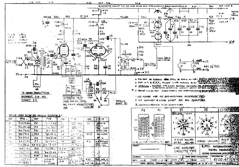