| John Broskie's Guide to Tube Circuit Analysis & Design |
| 30 June 2010
Aikido Cathode Follower [ACF]
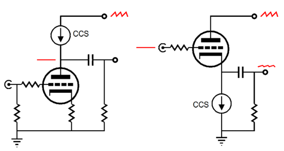
So what is required to make a good tube-based unity-gain buffer? For most tube fanciers, the immediate answer is to use a cathode follower. This solution makes a lot of sense, as the cathode follower offers a gain close to unity and a low output impedance. The cathode follower isn't the only circuit that will work as a buffer; for example, the plate follower and White cathode follower also provide unity-gain, a low output impedance and low distortion figure. The cathode follower, however is the most popular buffer, as it is the simplest. So simple in fact that a cathode follower can be made from just three resistors and one coupling capacitor as supporting parts. Several modifications to this simple circuit are possible. For example, the cathode resistor can be replaced by a choke, which will function as a constant-current source in AC terms. Another possibility is to replace the cathode resistor with a constant-current source circuit. A discrete constant-current source can be made from triodes, pentodes, FETs, MOSFETs, transistors, or ICs. (In fact, a fairly good constant-current source can be made from just one IXCY 10M45S current regulator and a resistor.)
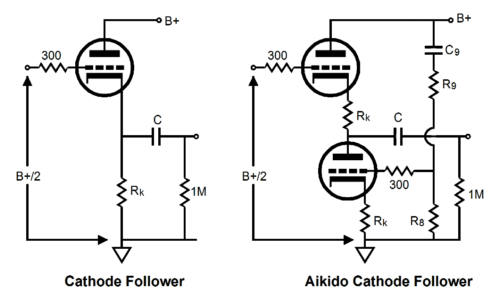
Cathode Follower Vs Aikido Cathode Follower
The triode is not as linear as a resistor so, ideally, it should not see a linear load, but a corresponding, complementary, balancing non-linear load. An analogy is found in someone needing eyeglasses; if the eyes were perfect, then perfectly flat (perfectly linear) lenses would be needed, whereas imperfect eyes need counterbalancing lenses (non-linear lenses) to see clearly. Now, loading a triode with the same triode—under the same cathode-to-plate voltage and idle current and with the same cathode resistor—works well to flatten the transfer curve out of that triode. Since the cathode follower already enjoys 100% degeneration at its cathode, the slight reduction in distortion by using the triode-based load is not as marked as in is in a grounded-cathode amplifier, but it is a worthwhile modification. In addition, the active load allows us to anticipate the power-supply noise that would normally appear at the output and counter the noise before it can appear.
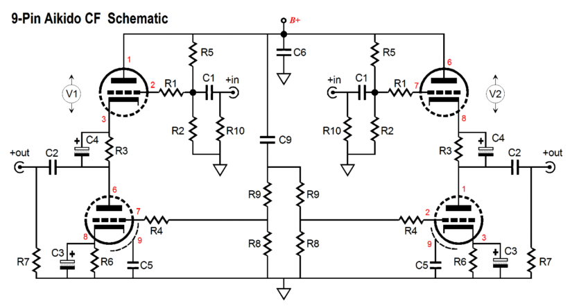
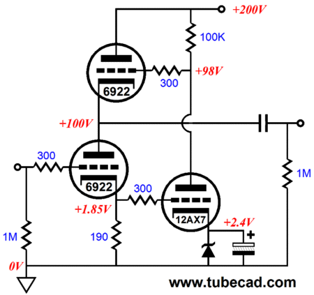
Imagine that the output coupling capacitor was infinitely large in value and that the load impedance was zero ohms and that the input was grounded. No power-supply noise could make it to the follower's output. Now imagine no power-supply noise at the output, but with no coupling capacitor or external load, with only the bottom triode providing a current path into the top triode and the B+ connection. In both scenarios, only the top triode sees the power-supply noise at its plate. Thus, any signal (power-supply noise) on the top triode’s plate will impose a current conduction variation in the top triode equal to Vnoise / (rp + [mu + 1]Rk). Since the both tubes are in series, the bottom triode must match this current variation to null the noise at the follower’s output. So, in the ideal setup, the top triode sees a fixed cathode and grid voltage, while its plate varies with the power-supply noise; and the bottom triode sees a fixed plate voltage, while its grid's voltage is varied to provoke a matching variation in current conduction. A triode's a grid is—by definition—mu times more effective than the plate in controlling triode's current conduction; thus, the bottom triode’s grid must see the power supply noise dived by the mu of the triode used. For example, a 6GC7 (with a mu of 20) will need to see 1/20th of the power supply noise at its grid; a 12AX7 (with a mu of 100), 1/100th of the power supply noise at its grid. Therefore, the voltage divider resistors must conform to the following ratios: R9/R8 = mu-1 and R9 = R8(mu-1) and R8 = R9/(mu-1) For example, with a 12AU7 (with a mu of 17), R9 would equal 17 x R8; with a 12AX7 (with a mu of 100), R9 equals 99 x R8. The coupling capacitor feeds the two-resistor voltage divider and it needs to big enough in value to ensure enough low-frequency bandwidth . Thus, C6 = 159155/(R9 + R8)/F, where F = frequency (say 10Hz) and the result is in μF; typical values fall between 0.047µF to 1μF.
No Gain, No Pain; No Hummer, No Bummer Yet passive line stages often prove inadequate, incapable of adequately driving high-capacitance cables or low-input impedances. Moreover, most active line-stage amplifiers can often impart the missing heft and solidity that are missing in many passive setups, even when the load is wimpy, but at the cost of greatly increased complexity and cost—and with some added noise and distortion. The Aikido cathode follower PCB/kit, in contrast, is a modest affair, consisting of one tube per channel (two triodes per tube envelope) and a handful of capacitors and resistors. This unity-gain buffer, using a modified cathode follower, offers a high input impedance, a low output impedance, low distortion, and a great PSRR figure. In addition, the ACF does not invert the phase. The ACF use is not limited to line-stages, as the ACF can be used in creating an active crossover or even a headphone driver, if the headphone's impedance is high enough. This new PCB is something I wanted to create for a long time now. In fact, I made the PCBs back in 2009, but I have been slow to release them. Why? The little that cannot be accounted for due to laziness can be ascribed to lack of time. The irony is that I long ago built up an ACF and I am quite pleased with its performance. I began with a good-sounding, passive line-stage preamp that used a fine 20k stepped attenuator (filled with carbon-film resistors) that sounded fuller than other passive line stages that I have constructed before. (Many metal-film resistor-based attenuators sound cold and brittle.) My fear was that adding the ACF to the signal path could only subtract, not add to the signal purity. I was, however, quite pleasantly surprised, as the now-active line stage seemed only to gain and lose nothing to the pure passive setup. Where the passive line stage offered great clarity but still somewhat thin sonic presentation, the ACF setup restored the weight and solidity to the music that the purely passive setup failed to impart. (Mahler on a diet sounds as bad as most diet food tastes.) My good friend Glenn described his own passive line stage as sounding a tad ghostly, whereas the addition of an ACF to his setup added needed solidity. I plan on adding an ACF to my Logitech Squeezebox Duet soon. (The ACF's high input impedance will greatly unload the Duet's output circuitry, thereby improving the sound.) And if I ever build the balanced setup that I have been planning on building, I will use one ACF per channel of my DacMagic's balanced outs. Remember, you effectively get +6dB more gain from balanced outputs.
Suitable tubes for the ACF are the 6AQ8, 6CG7, 6DJ8/6922A, 6H30, 12AU7, 12AT7, 12BH7, 5963, 5965, and ECC99. A PS-3 or PS-4 power supply would be perfect mate for the ACF. Aikido CF PCBs and kits are available now at the GlassWare-Yahoo store. Be sure to download the user guide PDF by clicking on the user guide image on the right.
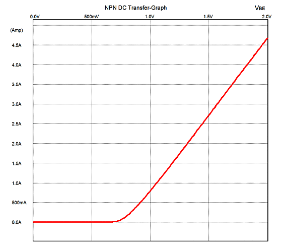
The Triadtron circuit exploits a feature of transistors: a well-defined and abrupt base-to-emitter voltage. Unlike triodes and pentodes, transistors exhibit a sharp turn-on voltage, as shown in the graph below.
Below 700mV, nothing; above 700mV, conduction. You can see why transistors are such a good fit for digital computers; when they are off, they are off; when they are on, they are on.
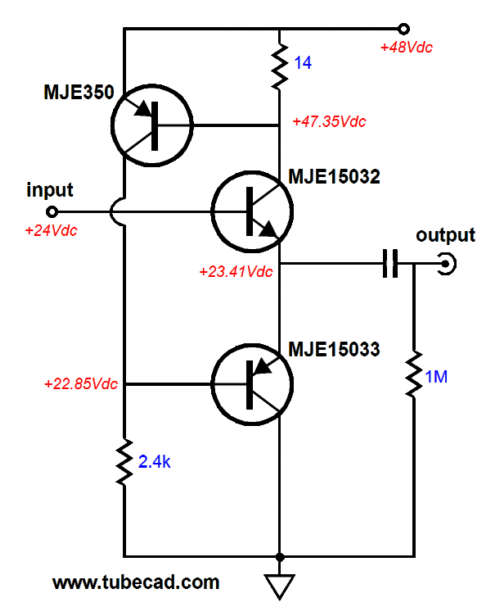
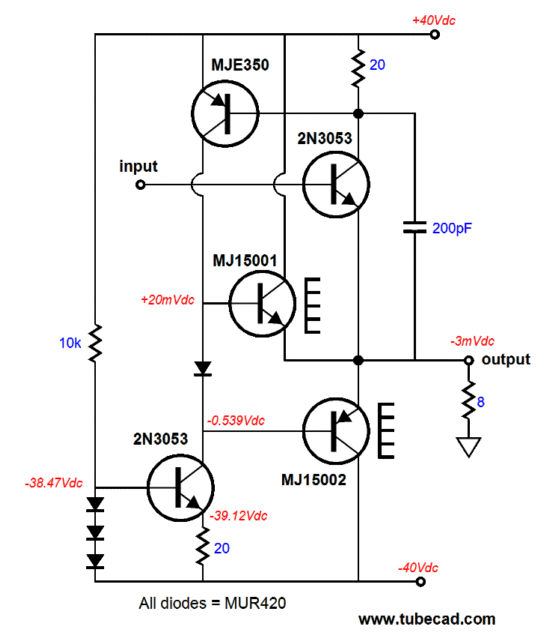
The Triadtron uses the consistent and sharp turn-on voltage as a free voltage reference, using the reference establish a fixed voltage drop across the current-sensing 14-ohm collector resistor, which, in turn, implies a fixed current through the two output transistors, MJE15032 & MJE15033. For if the 14-ohm resistor experienced a larger voltage drop, the PNP MJE350 transistor would greatly increase its conduction, which would pull up the voltage on the 2.4k resistor, which would then turn off both output transistors. Conversely, if the 14-ohm resistor saw a smaller voltage drop, the PNP MJE350 transistor would sharply decrease its conduction, which would collapse the voltage on the 2.4k resistor, which would then turn on both output transistors. In other words, DC feedback. The PNP MJE350 strives to maintain a fixed Vbe voltage drop across the 14-ohm resistor and constant current flow through the top output transistor. With no external load resistance to drive, the Triadtron would draw a constant current through its output stage, no matter what the input signal. With an external load, however, the bottom output transistor, the MJE15033, draws a varying current, while the top transistor, the MJE15032, draws a fixed current. In many ways, the top transistor, the MJE15032, can be seen as functioning like an inductive load in an SE power amplifier. In fact, much like an SE power amplifier, the Triadtron maximum symmetrical current output is set by the idle current through the output stage. So, yes, the Triadtron runs in class-A. But we can add diode to the circuit to allow the Triadtron to function in an asymmetric class-A/AB mode.
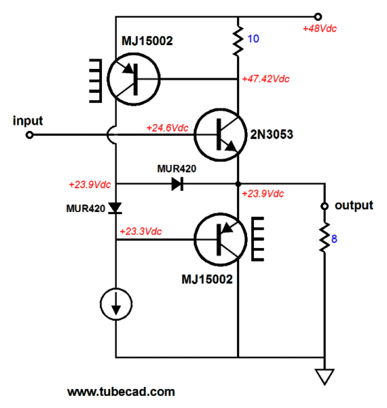
Note which transistors get a heatsink, as the 2N3053 is no longer an output transistor, although it does lend its small idle current (about 70mA) to the effort, which can come close to 3A with the 48V B+ voltage. In other words, the 2N3053 contributes a mighty 196mW to the 36W output. That's small change that you can believe in. Imagine a marketing guru grabbing hold of this circuit: "Forget about class-A/AB; this baby is class-A, single-ended all the way." The topmost MJ15002 will start driving the external load when the topmost MUR420 rectifier begins to conduct, otherwise it has no current path into the load. Now imagine if the the small 2N3053 were replaced by a big TO-247 or To-3 power transistor such as the MJ15001 and if the idle current was raised to 1A. Such an amplifier would run in class-A up to 4W of output, before moving into class-AB. Or we might try something along the following lines:
One of the rectifiers has been replaced by an NPN output transistor, which should result in more stable idle current, as the MJE350's Vbe voltage should remain more constant, relieved of driving the external load resistance.
I-to-V Triadtron
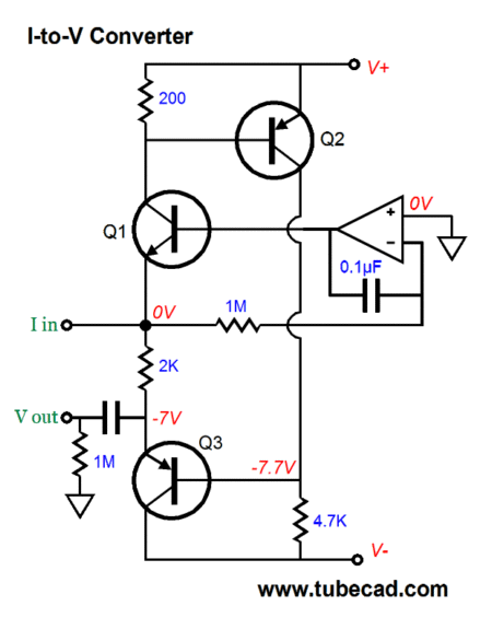
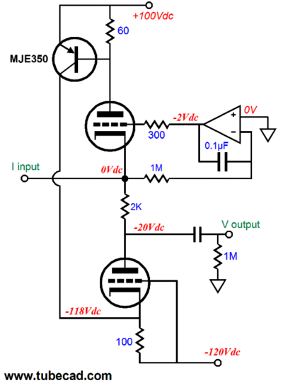
This I-to-V converter uses a 2k resistor to establish the current-to-voltage conversion ratio, wherein 1mA in equals 2V out. The OpAmp-based DC servo keeps the input at 0V and transistor Q2 does its job of of maintaining a constant current following through Q1 by varying the voltage preset at Q3's base. "Where are the dang tubes?" I can hear many readers thinking. Well, here is a hybrid Triadtron I-to-V converter.
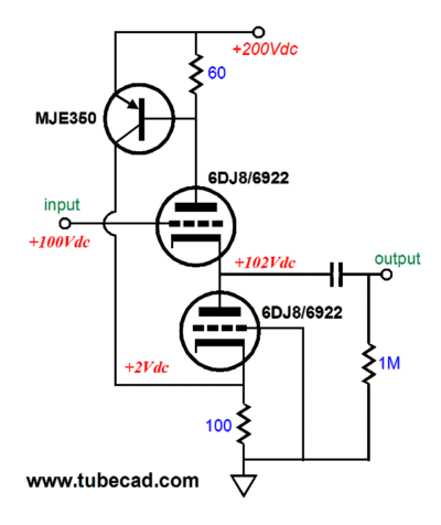
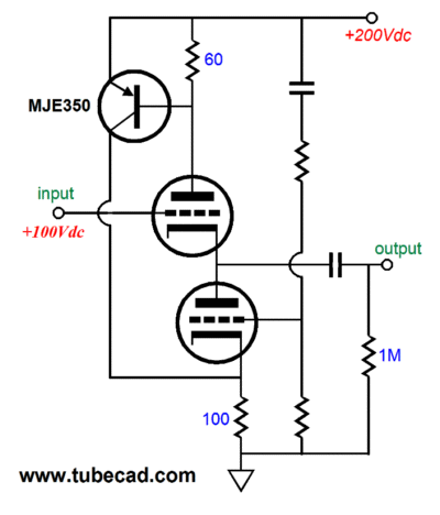
The actors and set have changed, but it's the same play. To keep the tubes in their linear region, the idle current has been increased to 10mA and the power supply voltages have been increased for the same reason. The same 2k I-to-V resistor is used and the MJE350 performs the same tasks, albeit in a different fashion. If the PNP transistor's collector had attached to the bottom triode's grid, the phase would be off, as an increase in the MJE350's conduction must result in a decrease in the bottom triode's conduction. Attaching the collector to the cathode restores the correct phasing of conductions. Note how the the PNP transistor and the triodes all conduct the same idle current. The transistor must at least match the triode current conduction, if it is going to obtain the largest symmetrical voltage swings at the output. By the way, we can use the same basic topology to create a hybrid unity-gain buffer.
This hybrid circuit functions much the same as its all-solid-state cousin. The top triode will draw a near constant current, while the bottom triode will see all the current variations required to drive the external load. In fact, we might try an Aikido version of this topology.
The added resistors and capacitor allow us to inject some of the B+ noise into the bottom triode's grid, which will then work to null the PS noise at the output.
Inverted Triadtron
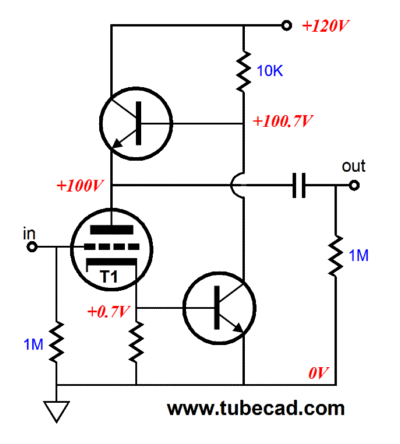
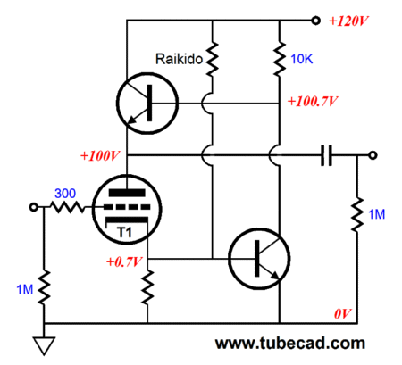
Here the current sensing resistor has been moved to the cathode and the bottom NPN transistor controls the top transistor. When I first sketched this circuit, my guess was that this circuit would realize a gain equal to the mu of the triode used, as cathode resistor was effectively bypassed by the bottom transistor. In fact, the circuit develops only about 70% of the mu. Nonetheless, it offers low distortion and low output impedance; moreover, it runs on a relatively low B+ voltage. The PSRR is good, but not great. Making it great requires an Aikido-like technique: the addition of resistor, Raikido.
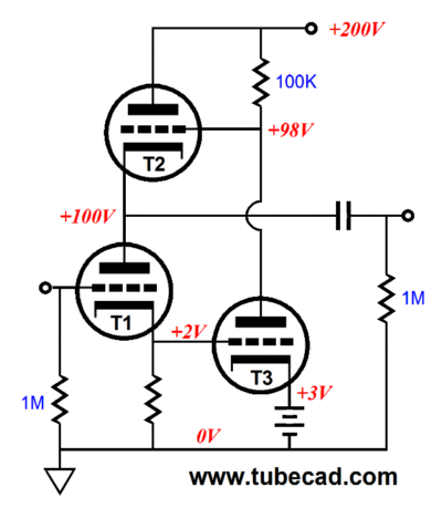
Once you have grokked this topology fully, you can move on to seeing how it works with just N-type devices, the triode and the two NPN transistors. Well, if it only uses N-types, why not replace the transistors with triodes?
The big problem we face with the all-tube version is the relatively low-gain the triodes offer. Thus, triode T3 should be either a high-mu triode, such as the 12AX7, or a pentode. Triodes, T1 and T2, should be low-rp types, such as the 6DJ8 or 6H30 or 12BH7, although I bet that 6SN7s or 12AU7s would work just fine. I used a 3V battery in the above schematic to bias triode T3, so as to impress the need for a low impedance and fixed voltage. The fixed voltage probably is not as important as the low-impedance feature. The following design example would be a good place to start experimenting.
Next Time
//JRB |
E-mail from GlassWare Customers
High-quality, double-sided, extra thick, 2-oz traces, plated-through holes, dual sets of resistor pads and pads for two coupling capacitors. Stereo and mono, octal and 9-pin printed circuit boards available.  Aikido PCBs for as little as $24 http://glass-ware.stores.yahoo.net/
Support the Tube CAD Journal & get an extremely powerful push-pull tube-amplifier simulator for TCJ Push-Pull Calculator
TCJ PPC Version 2 Improvements Rebuilt simulation engine *User definable
Download or CD ROM For more information, please visit our Web site : To purchase, please visit our Yahoo Store: |
|||


| www.tubecad.com Copyright © 1999-2010 GlassWare All Rights Reserved |