12 February 2005 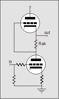
Where have these blogs been going? We started with the White cathode follower, then the Taylor amplifier, then the Taylor source follower, then the Macaulay amplifier, and then the Broskie-Macaulay amplifier, each defining a signpost on the same road. The idea behind all these seemingly different circuits is that a push-pull amplifier can be made that uses the same polarity output devices, but dispenses with the need for a phase splitter by sensing the current flow through a primary output device to derive the needed drive signal for the other output device.
The Murray amplifier (Above) looks like it might be located on the same road; but once again, looks deceive, as both output devices finds their drive signal from the same input, no inverse reflecting the other output device’s current.
On the other hand, there is a circuit that can legitimately be found along this road: the SRPP. It is also a push-pull amplifier that cheats the system, by doing away with a phase splitter.
I have displayed how to make transistor-based SRPP circuit, but now it’s time to supercharge the SRPP and translate it from vacuum to silicon. But let’s make our translation in easy steps.
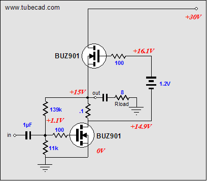
The circuit above is a MOSFET-based SRPP. As the amplifier stands, it will not easily translate into a working amplifier without first carefully matching the output MOSFETs. Second, the amplifier will not offer a low output impedance, as it falls somewhere between being a current amplifier and a voltage amplifier, with an output impedance of 23 ohms. So, the next step is to clean up the bottom output device’s output.
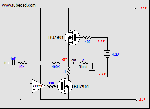
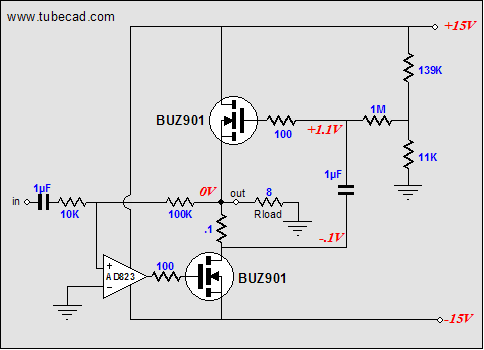
The OpAmp’s feedback loop encompasses the bottom MOSFET, greatly lowering its distortion and output impedance. The OpAmp also sets the DC offset, which is important in this directly coupled amplifier. The next step is to eliminate the battery.
The OpAmp keeps the output centered at ground and the top MOSFET sets the idle current, via the two-resistor voltage divider that DC references its gate. One interesting feature of this circuit is that the sense resistor’s value can readily be changed without also changing the idle current.
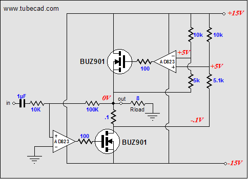
The last step is to bolster the top MOSFET by giving it its own OpAmp.
We have arrived. The SRPP has been translated and supercharged. The two OpAmps ensure low distortion and output impedance, while maintaining a low DC offset and a steady idle current.
No, this is not my proposal of what a perfect amplifier should look like, but rather a filling in of an obvious hole in our array of amplifiers on the same theme. How would the amplifier sound if built? Probably, fairly good, but I am only guessing. But if you decide to give it test drive, please share your results with us.
//JRB
|
|
|
|
Kit User Guide PDFs
Click image to download


Support the Tube CAD Journal
Only $12.95
to keep track of
your
tube and part collection
TCJ My-Stock DB
TCJ My-Stock DB helps you know just what you have, what it looks like, where it is, what it will be used for, and what it's worth. TCJ My-Stock DB helps you to keep track of your heap of electronic parts. More details.
List all of your parts in one DB.
Add part Images.
One-click web searches for information.
Vertical and horizontal grids.*
Create reports as PDFs.*
Graphs added 2D/3D: pie & bar.*
More powerful DB search.
Help system added.
Editable drop-down lists for location, projects, brands, styles, vendors and more.
*User definable
For more information, please
visit:
|
 SRPP on Steroids