| John Broskie's Guide to Tube Circuit Analysis & Design |
02 April 2016
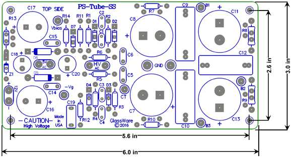
New Power Supply for Tube Power Amplifiers: PS-Tube-SS
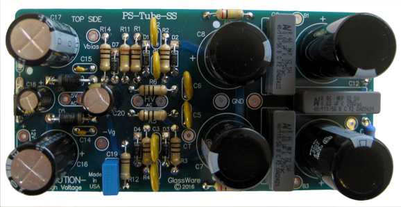
The "SS" stands for solid-state rectifiers. The PCB holds seven rectifiers, five high-voltage, high-speed rectifiers and two low-voltage, super-fast rectifiers. The is PCB is a compact 3 by 6 inches. With four mounting holes.
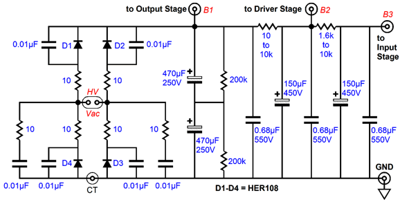
Tube power amplifiers usually require several B+ voltages, the highest (B1) for the output tubes, the next highest (B2) for the either the phase splitter or driver stage, and the lowest (B3) for the input stage. This cascade of DC voltages results from cascading RC filters, so the input stage receives the cleanest DC voltage.
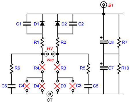
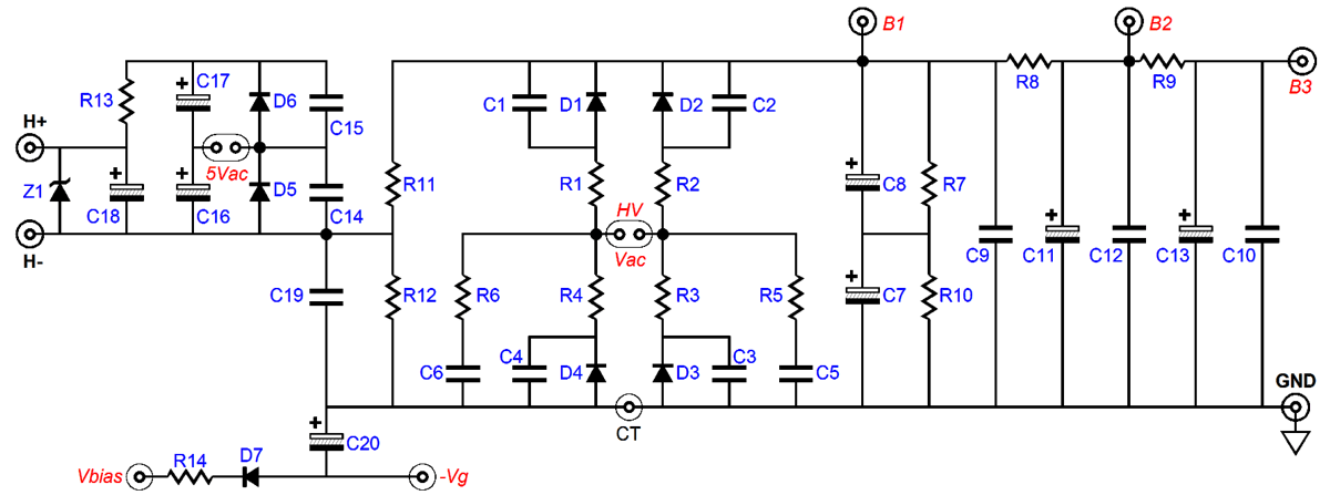
The schematic above shows the full-wage bridge rectifier configuration, which requires four rectifiers. This is only an option for those whose power transformer secondary does not hold a center-tap. Most tube-power transformers, however, do hold a center-tap and capacitor C3 & C4, rectifiers D3 & D4, and resistors R3 & R4 must be left off the PCB.
Note how capacitors C7 & C8 are in series. Why? Both capacitors are 470µF with a 250V rating, so the two in series effectively become one 235µF capacitor with a 500V rating. Resistors R7 & R10 define a 50% voltage divider, which ensures equal voltage sharing between the two capacitors. This brings up the issue of maximum DC output voltage. The maximum DC output voltage must be less than 450Vdc, as that is the voltage rating of capacitors C11 & C13. This means that maximum secondary voltage with a full-wave-bridge rectifier circuit is 300Vac, as that will rectify up to about 424Vdc; with a full-wave-center-tapped rectifier circuit is 600Vac-CT (i.e. 300V-0V-300V). (By the way, resistor R8 could be replaced by an external power-supply choke [inductor]. Ideally, an inductor displaces no DC voltage; real inductors, on the other hand, do so due to their DCR. Nonetheless, an inductor with a DCR of 100 ohms will only lose 10Vdc with a current draw of 100mA, yet provide the ripple reduction of a vastly larger RC resistor.)
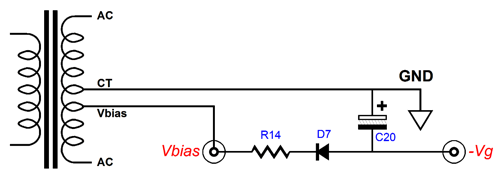
Many classic tube amplifier power transformers offer a bias-voltage tap on the B+ secondary. This single tap is used in a simple half-wave rectifier circuit. Resistor R14 limits the inrush current and capacitor C20 accumulates the stored negative bias voltage. The capacitor supplied in the kit is rated for up to 50V use, so the negative-bias tap is limited to no more than 33Vac. If the AC voltage is greater than this, a higher-voltage capacitor must be used, say a 100V device.
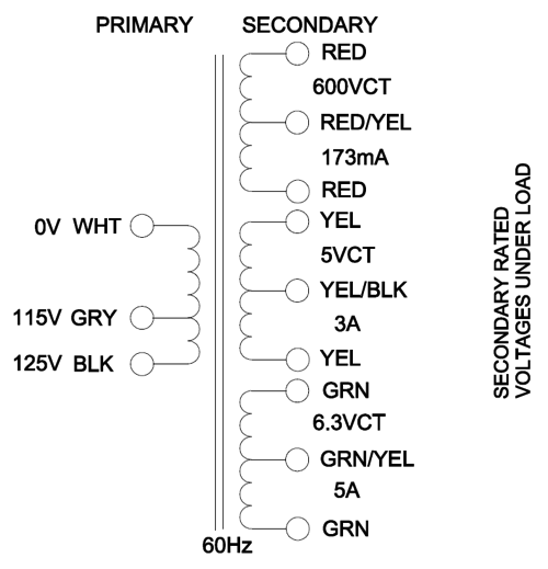
The Hammond 272FX transformer is a good example of a power transformer designed for use in a tube power amplifier.
This transformer does not offer a negative-bias tap, but it does hold a 5Vac rated for 3A for heating a tube rectifier' heater element.
What do you do with the 5Vac winding if you are using solid-state rectifiers, not a tube rectifier tube, such as the 5AR4 or 5Y3? With the PS-Tube-SS PCB, this 5Vac can be put to use to create a 12Vdc power supply for the amplifier's input stage. What about the output tubes heaters? Most output tubes hold heater that draw at least 1.5A of current. For example, four EL34 tubes will draw 6A @ 6.3V, which are more easily powered by the power transformer's 6.3Vac winding.
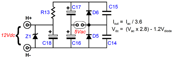
The PS-Tube-SS PCB holds a simple DC heater power supply that consists of a two-rectifier voltage doubler and an RC filter. Since no tube rectifier is used with the PS-Tube-SS PCB, the 5Vac that would otherwise go to waste can be put to use powering this voltage doubler. The MUR410G rectifiers (D5 & D6) are ultrafast types with a small voltage drop. Just how much DC develops depends on several factors. First, many old tube-power transformers were built back when the wall voltage was much lower than it is today. I have seen a few rated for 110Vac, for example. Most are were built with 115Vac as the intended input voltage. This means that if your wall voltage is higher (mine is 123Vac), then more than 5Vac will be presented by the old 115V transformer. Second, if the 5Vac has a current rating of 3A and you only draw 0.3A of DC from it, the transformer's poor regulation will result in more than 5Vac of secondary voltage. Having noted these two generators of higher voltage, we move on to voltage losses. If the voltage doubler circuit employed loss-less rectifiers, the 5Vac input voltage would rectify up to 14.14Vdc. The two rectifiers exhibit a voltage drop of about 0.6V each, so 1.2V must be subtracted from the 14.14Vdc, yielding 12.94Vdc. In order to reduce this voltage to 12Vdc, a series RC resistor is used, R13. This resistor along with capacitor C18 define an RC filter that smoothes away ripple. In addition, zener diode Z1 clamps the out voltage to 12Vdc. How big should resistor R13 be in value? Its value depends on the amount of current drawn and the amount of DC voltage created by the voltage doubler. For example, if the raw DC voltage is 15V and the current draw id 300mA, then a 10-ohm resistor is needed, as 0.3A against 10 ohms results in a 3V voltage drop. This 10-ohm resistor would then dissipate 0.9W of heat. Sounds too complicated? Do not panic. Attach the load and start with the 10-ohm resistor, if less than 12V develops at the output, then replace it with the 3.3-ohm resistor… If replacing R13 with a jumper fails to develop 12Vdc, then either the 5Vac winding or the wall voltage lacks sufficient oomph. What if you plan on using the 5Vac winding on a 300B output tube, could the 6.3Vac winding be used with the voltage-doubler circuit? Yes, but the voltage drop must be greater across resistor R13, so it must be larger in value and it will dissipate much more heat. This brings up the issue of not using a classic tube power transformer, but a two transformers. Say you plan on using a toroidal transformer with two 6.3Vac winding and another toroidal with a secondary of 240Vac. In this case, one 6.3Vac winding can be used to heat the output tube heaters and the other 6.3Vac for powering the 12Vdc power supply on the PS-Tube-SS PCB. The 240Vac will rectify up to about 340Vdc. Of course, the PS-Tube-SS kit can be used with tube circuits other than tube power amplifiers, such as line-stage and tube headphone amplifiers. Many topologies, such as the SRPP or cascode or Aikido topology, use triodes standing atop another, which makes referencing the heater power supply to the B+ power supply a small chore. With one tube atop another and a single heater power supply, the top and bottom heaters cannot share the same heater-to-cathode voltage relationships. With such totem circuits, the safest path is to reference the heater power supply to a voltage equal to one-fourth the totem-pole stage's B+ voltage; for example, 75V, when using a 300V power supply. Resistors R11 & R12 on the PCB establish the reference voltage, as shown below in the PCB's entire schematic.
Click on image for larger view Note how R11 & R12 can be left off the PCB, which will allow the 12Vdc output to float, yet be AC grounded.
The new PS-Tube-SS kit is now available at the GlassWare web store. The kit includes all the parts, including many alternate resistor values for the three RC filters, and four aluminum hex standoffs and 12-page user guide.
Next Time
User Guides for GlassWare Software Since I am still getting e-mail asking how to buy these GlassWare software programs:
For those of you who still have old computers running Windows XP (32-bit) or any other Windows 32-bit OS, I have setup the download availability of my old old standards: Tube CAD, SE Amp CAD, and Audio Gadgets. The downloads are at the GlassWare-Yahoo store and the price is only $9.95 for each program. http://glass-ware.stores.yahoo.net/adsoffromgla.html So many have asked that I had to do it. WARNING: THESE THREE PROGRAMS WILL NOT RUN UNDER VISTA 64-Bit or WINDOWS 7 & 8 or any other 64-bit OS. One day, I do plan on remaking all of these programs into 64-bit versions, but it will be a huge ordeal, as programming requires vast chunks of noise-free time, something very rare with children running about. Ideally, I would love to come out with versions that run on iPads and Android-OS tablets.
//JRB |
Kit User Guide PDFs
And
High-quality, double-sided, extra thick, 2-oz traces, plated-through holes, dual sets of resistor pads and pads for two coupling capacitors. Stereo and mono, octal and 9-pin printed circuit boards available.
Designed by John Broskie & Made in USA Aikido PCBs for as little as $24 http://glass-ware.stores.yahoo.net/
The Tube CAD Journal's first companion program, TCJ Filter Design lets you design a filter or crossover (passive, OpAmp or tube) without having to check out thick textbooks from the library and without having to breakout the scientific calculator. This program's goal is to provide a quick and easy display not only of the frequency response, but also of the resistor and capacitor values for a passive and active filters and crossovers. TCJ Filter Design is easy to use, but not lightweight, holding over 60 different filter topologies and up to four filter alignments: While the program's main concern is active filters, solid-state and tube, it also does passive filters. In fact, it can be used to calculate passive crossovers for use with speakers by entering 8 ohms as the terminating resistance. Click on the image below to see the full screen capture.
Tube crossovers are a major part of this program; both buffered and un-buffered tube based filters along with mono-polar and bipolar power supply topologies are covered. Available on a CD-ROM and a downloadable version (4 Megabytes). |
||


| www.tubecad.com Copyright © 1999-2016 GlassWare All Rights Reserved |