| John Broskie's Guide to Tube Circuit Analysis & Design |
|
09 November 2017 Post 401
Special Thanks If you have been reading my posts, you know that my lifetime goal is reaching post number one thousand. I have 599 more to go. My second goal is to gather 1,000 patrons. I have 940 patrons to go. If you enjoyed reading this post from me for the last 18 years, then you might consider becoming one of my patrons at Patreon.com. It would make a big difference to me. Thanks.
More Electrostatic Ideas
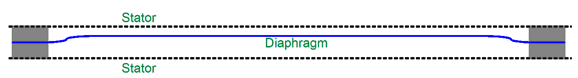
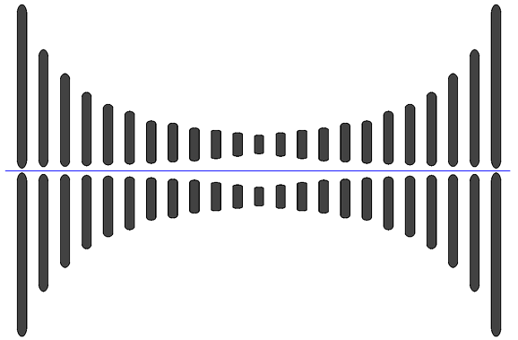
Those who have access to a good strobe light and function generator, tell me that you can clearly see the diaphragm move like a piston, with a flat surface. What if we didn't what flat, piston-like movement, but preferred a bowed excursion of the diaphragm, could we make the diaphragm bow?
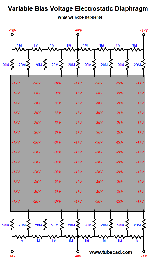
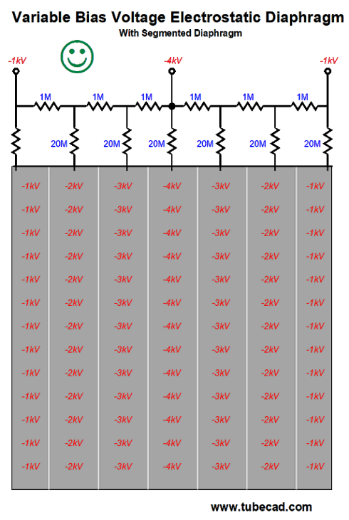
You may ask why we might prefer bowed over flat motion. As I see it, it is a natural movement, more like the movement of guitar strings or a drum skin. More importantly, a curved stator is naturally more stiff and less inclined to flap. In addition, should the diaphragm slap a stator, only the center would touch, not the entire surface. Moreover, we could expect much greater SPLs (sound pressure levels), as the diaphragm could move much further. The big problem is that electrostatic field force falls off with the square of the distance. Move the stator twice as far and you get one quarter the force; move three times as far, one ninth the force. Thus, if we used curved stators on a conventional electrostatic speaker, the result would be the opposite of bowing, as the center would move the least. The workaround that I suggest is to use a bias-voltage gradient across the diaphragm, so the center gets a much higher voltage than the two sides. The higher the bias voltage, the greater the diaphragm movement. Of course, there is a limit to how much voltage can be applied, as the air's own breakdown-voltage will be encountered (30 kV/cm); in addition, humidity will reduce the breakdown voltage. With a bowed stator, however, the greater distance from the diaphragm allows a higher bias voltage to be used in the center due to the increased spacing. How could such a voltage gradient be realized? Here is one tempting idea.
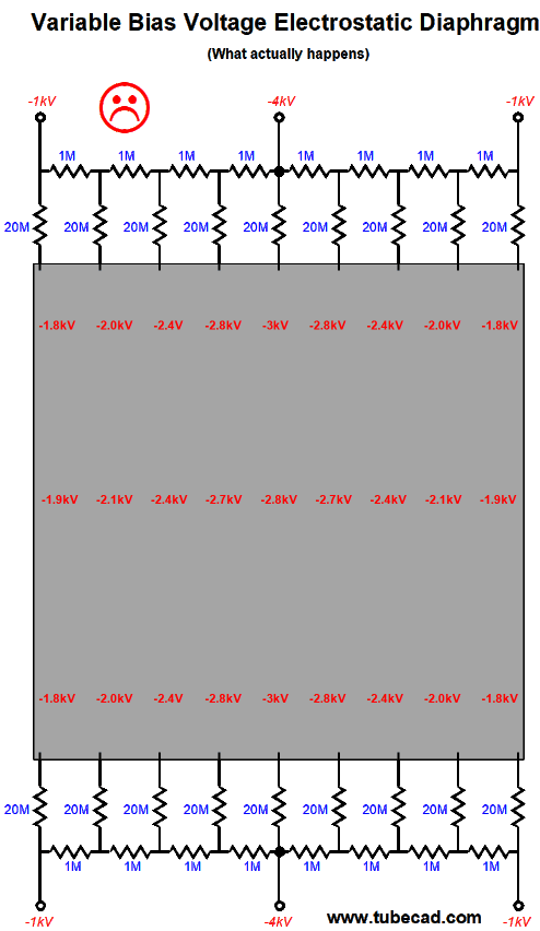
It looks like it should work, but it doesn't, as the entire diaphragm surface is coated with a slightly conductive covering, which prevents the center from maintaining 4kV.
One workaround would be to leave thin vertical stripes of bare diaphragm, which would create vertical bars of arrayed voltage. Long strips of tape could be laid down before applying the conductive coating; afterwards, the tape would be pulled away.
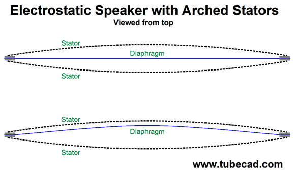
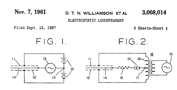
Note how only top series resistors are needed. I have shown only seven segments on the diaphragm, which might be sufficient for a 7-inch-wide diaphragm. With a 30-inch-wide diaphragm, we might use 30 stripes or more. In this example, the voltage gradient extends from 1kV to 4kV, so the stator-to-diaphragm spacing can only vary by two to one. If the voltage gradient extends from 1kV to 9kV, spacing can span from one to three; for example, from 0.1 inch to 0.3 inch. Or, would this work? What complicates this puzzle is that the capacitance between stator and diaphragm will vary with the spacing; the greater the spacing, the less the capacitance. Remember the formula for the capacitance between two plates includes area divided by distance between the plates. Twice the distance, half the capacitance. Thus, we should impose a voltage gradient whose ratio between starting and ending voltage would equal the starting voltage against the spacing ratio to the third power. For example, if the stator-to-diaphragm spacing varied by two to one, then the voltage gradient should extend from 1 to 8, as in 1kV to 8Kv. Since we want the center to be free to bow, the diaphragm should only be affixed to the stators at its sides. Is this a problem? No, as this is standard practice with curved electrostatic panels, where only the top and bottom of the diaphragm are attached to the curved stators, with the sides left unattached. Okay, what about the other electrostatic type, the one that few know about, the inverted electrostatic, where the diaphragm is driven, not the stators, as shown on the left in the image below.
The stators must now be polarized by two high voltage power supplies, as one must be charged positively, while the other is charged negatively; the diaphragm is at ground potential. The diaphragm cannot contain the voltage gradient, as it directly receives the audio signal. Thus, if we used to bowed stators, the voltage gradient must spread across the stators. For example, the positively charged stator would see +1kv at its sides and +8kV at its center, while the negatively charged stator would see -1kv at its sides and -8kV at its center. Note the construction problem: if we used perforated sheet aluminum, how do you impose a voltage gradient across a low-resistance material? One workaround would be to plastic coat the stator and then spray on long vertical stripes of conductive paint. I doubt that the plastic coat can withstand a 9,000 volt differential before breaking down. (I am sure that the dyes used in coloring the plastic coat will affect the plastic-coat's resistance, with black offering the least resistance. But then, I could be wrong.) Another workaround would be to sheathed wire or the rectangular rods I described in my last post, which served as an acoustical lens.
Another possibility would be to make the stators out of printed circuit board, which could either have etched or routed vertical lines created. Double-sided PCB material could be used, with the outside copper grounded, which would both make the stator safer to touch and would create a capacitor, as the two copper sides would create a fiberglass-filled capacitor, which would prove useful in this design. Another possibility would be to use multi-layer PCB board. A multi-layer, perforated PCB has traces within its center. Well, long, fat, vertical traces could be created, with the outside PCB material providing insulation to both our probing fingers and the diaphragm.
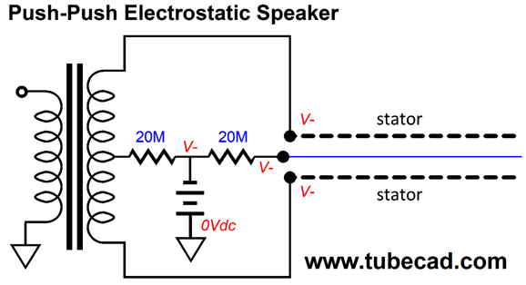
Push-Push, Not Push-Pull, Electrostatic Speaker
As one stator swings more negative, the other swings less negative. The more negative stator pushes harder against the diaphragm, while less negative stator pushes less hard, so the diaphragm moves away from the more negative stator. Coulomb's law states that the force between two charged objects is directly proportional to the product of the quantity of charge on the objects and inversely proportional to the square of the separation distance between the two objects. Note the two high-resistance 20M resistors. They allow either positive or negative high-voltage bias voltage to develop on both stators and the diaphragm. Which polarity would be better, positive or negative? Since most dust is negatively charged, I would recommend negative charging, which would repel both the diaphragm and dust. What happens if you touch a stator? If the stator isn't insulated, you will get a shock. Fortunately, the 20M resistor limits the current flow to no more than a steady 1/2oth of a milliampere with a 1kV bias voltage, which might be below the threshold of perception. The interesting question here is How much diaphragm tension is needed in this variation on the electrostatic speaker? My quick guess would be much less than usual. Another interesting question is, How would it sound? Perhaps the conventional electrostatic imparts a jumpy quality, while this variation might bestow a more reserved, constrained quality. Who knows? But I would love to know the answer. There is one experiment that I have wanted to try for decades now, but I never seemed to have the time to perform it. It's shocking how little free time one is allotted per lifetime. So far this year, I have watched zero hours of broadcast TV and less than three TOTAL hours of Netflix or DVD or YouTube videos. Returning to the experiment, I have wanted to take a woofer with two voicecoils and run one coil with a separate power amplifier, whose input signal would be derived from a cone-centering circuit. Such a circuit could be made from gluing a small piece of aluminum foil to the diaphragm and placing a metal disk on either side of the foil and then measuring the capacitance between the two effective capacitors. Or some optical measuring arrangement could be employed. No matter how the signal is derived it would achieve the same result—namely, the diaphragm would be forced back to its center position. Of course, the amplifier feeding this second coil would have to exert less force than the actual signal amplifier, or the woofer would not move at all. Would such a setup produce more detailed, taut, well-defined bass? I don't know, but I would love to find out.
Driving Electrostatic Speakers In at least one way, an electrostatic panel is a safer load for an amplifier, as no inductive kick-backs are encountered, which improves the MOSFET's survival odds, assuming direct drive and no transformers or other inductive devices are used. Remember, a capacitor opposes a change in voltage, while an inductor opposes a change in current. Speaking of current, it is worth mentioning that charging a capacitor quickly requires not just voltage, but current. Slewrate against capacitance equals current. And slewrate equals Slewrate = (2 × pi × Freq × Vpk) / 1,000,000 For example, if we want to swing 1kVpk at 10kHz, we need a slewrate of 62.8V per microsecond (or µS). Given an electrostatic panel with 10nF (0.01µF) and a peak voltage swing of 1kV at 10kHz, 628mA of current will be required. If the needed current isn't available, the capacitance will still slowly charge up, but not fast enough to achieve 1kV at 10kHz. If you actual bother to run the math, you discover that many electrostatic speaker amplifiers cannot deliver full power at full bandwidth. This is not quite the failing that you might imagine, as most music does not come close to asking for full power at 20kHz—and if does, it isn't worth listening to. In other words, as long as music and not a sinewave generator is used as the signal source, we are unlikely to notice the limited full-power bandwidth. Nonetheless, we want a flat output at lower voltage swings.
Triodes for Electrostatic Speakers
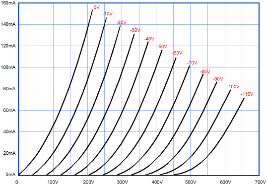
For example, with a B+ voltage of 470V and an idle current of 5mA, we can only swing the plate down to 170V, creating a negative voltage swing of 300V. An electrostatic panel might need voltage swings of +/-1500V to dance. The obvious solution is an audio output transformer. The problem is that finding one with a 1:5 winding ratio is difficult. Another—and possibly far better—idea would be to use an autoformer instead. An autoformer is like half a transformer, the good half, I like to say, as they offer wider bandwidth and more power output for a given size.
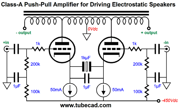
The autoformer holds one long coil of wire, with several taps along its length. We ground the center tap and and the triodes to the two flanking inner taps. The step ratio would be 1:5, so our 300V plate-voltage swings will become 1,500 volt swings at the stator, with peak-to-peak swings across both stators equal to 3,000V. Of course, nothing come free in electronics, so we must pay by reducing the available current swings at the stators by fivefold. And the load capacitance gets reflected to the triode by 5², or 25 fold. This output stage is "naked," by which I mean that is holds no driver or input stages. This means that the big balanced signals will have to come from the line-stage amplifier. This might sound too daunting, but if high-efficiency tubes are used, such as triode-connected EL34 pentodes, we need only deliver 30V peak voltage swings to the EL34 grids. The 1µF at each input decouples the negative power-supply-rail noise from the inputs. The constant-current sources set the idle current, but limits the output stage to class-A push-pull operation.
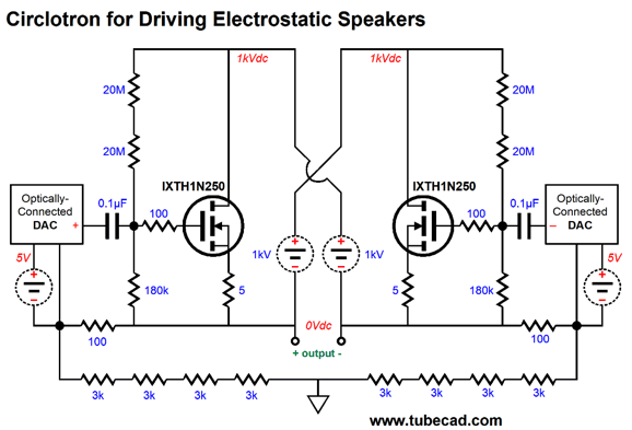
Circlotron for Electrostatic Speakers
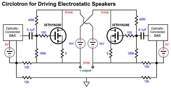
Two voltage-out DACs are required per channel, each with its own floating 5V power supply. Two negative feedback loops set the gain. Yes, I know that this arrangement looks crazy. Think of it this way: as the DAC's output voltage swings positive, the MOSFET it controls conducts more current, which will swing the output positive. What prevents it from swinging all the way up to the B+ voltage is the 100 and 12k resistors. As the output swings up the DAC's ground lags behind due to the two-resistor voltage divider made up from the 100 and 12k resistors. If the output swing too high, the DAC's out would become negative relative to the MOSFET's gate. The same holds true for the opposing DAC, as its output will swing negative, while the other DAC's output swing positive. If this output swings too far negative, the DAC will effectively be delivering a positive output signal, rather than a negative one. The result is that the two negative feedback loops set a fixed gain—providing the MOSFETs exhibit a high enough transconductance. Although compared to tubes, MOSFETs offer a screaming transconductance; compared to transistors, they fall short. Pull back and notice how this Circlotron is quite Zen-like, as all the gain results from the transconductance of the output MOSFETs. While you have pulled back, also note how the 100-ohm negative feedback resistor is effectively in series with the MOSFET's gate, which precludes us from using a 10k resistor in it's place. This brings up the issue of the power dissipated by the 12k feedback resistor. Assuming that we got a peak voltage swing of 1kV into the electrostatic panel, each 12k resistor would see a 500Vpk swing, which means each resistor would dissipate 10.4W. Of course, with music playback, they would never get that hot. Still, it is a sound practice to overbuild. At the very least, we could use four 3k 3W resistors in series.
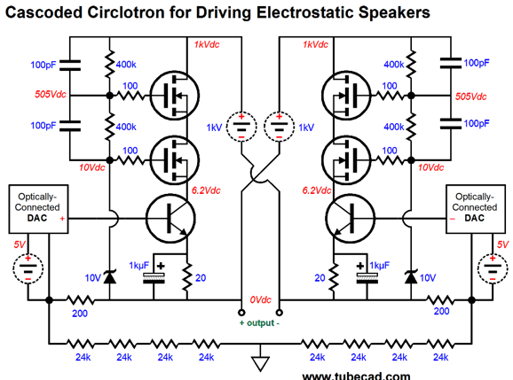
Many voltage-out DACs exhibit a DC offset at their outputs equal to half of the analog power-supply voltage, which is often 3.3Vdc, so the DC offset is 1.65Vdc. Now this voltage is nowhere near enough to turn on a MOSFET (at least not those other than lateral types), but it is more than enough to turn on a transistor. Indeed, only 0.6Vdc to 0.7Vdc is needed. What do we do with the leftover voltage, all 0.9 volts of it? We can use it to set the idle current. The following design uses 2N3053 NPN transistors as the chief controlling devices and 2.5kV N-channel MOSFETs in cascode to protect the low-voltage transistors and dissipate most of the heat. Think of them as voltage sponges.
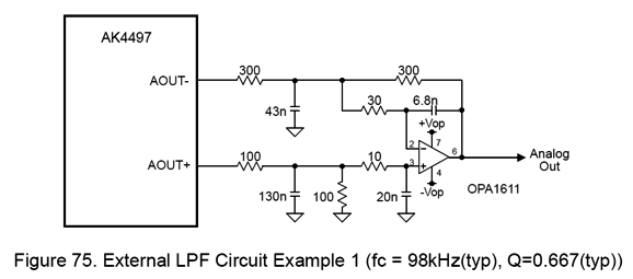
The 20-ohm emitter resistors set the idle current to 45mA per side, which means a total heat dissipation of 90W at idle per channel. Yes, we are talking class-A here. Note the 1kµF bypass capacitors across the 20-ohm resistors. Normally, these would be a no-no, but with the class-A operation the capacitors should never become overcharged. (We could plate two diodes in series and them both in parallel with the bypass capacitors, which would limit the peak capacitor voltage to about 1.4V.) This electrostatic Circlotron can swing +/- 1kVpk. The gain is almost equal to 500 per side, but as we are effectively feeding the entire output stage a balanced input signal, the final gain is close 1,000 (or +60dB) across the electrostatic speaker. Each DAC is required to put out only 1Vpk. In SPICE simulations, the above circuit yielded a -3dB frequency of 63kHz with a 3nF load capacitance. (Most electrostatic panels average about 300pF per square foot of panel, which would yield 10 sq ft with the 3nF of capacitance.) With a 10nF load capacitance, the -3dB frequency was 19kHz. Here is a thought: since DACs require a low-pass post filtering, why not let the electrostatic speakers themselves define the low-pass filter (or at least part of it)? Indeed, we probably should add more filtering, which might be as little as adding two emitter-stopper resistors; or, as elaborate as an OpAmp-based 2nd-order low-pass filter. Here is an example of post low-pass filtering and of converting balanced voltage output into an unbalanced signal. In addition, this differential circuit eliminates the DC offset present at the DAC's AOUT- and AOUT+ pins.
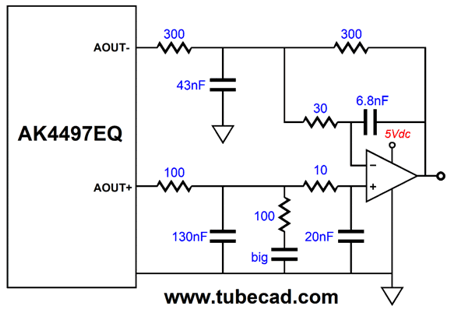
What if we want to retain the DC offset, not eliminate it? All we need to do is add one capacitor.
With the added large-valued capacitor, the DC offset is preserved.
//JRB
User Guides for GlassWare Software
For those of you who still have old computers running Windows XP (32-bit) or any other Windows 32-bit OS, I have setup the download availability of my old old standards: Tube CAD, SE Amp CAD, and Audio Gadgets. The downloads are at the GlassWare-Yahoo store and the price is only $9.95 for each program. http://glass-ware.stores.yahoo.net/adsoffromgla.html So many have asked that I had to do it. WARNING: THESE THREE PROGRAMS WILL NOT RUN UNDER VISTA 64-Bit or WINDOWS 7 & 8 or any other 64-bit OS. I do plan on remaking all of these programs into 64-bit versions, but it will be a huge ordeal, as programming requires vast chunks of noise-free time, something very rare with children running about. Ideally, I would love to come out with versions that run on iPads and Android-OS tablets.
//JRB
|
|
Kit User Guide PDFs
Only $12.95 TCJ My-Stock DB
Version 2 Improvements *User definable Download for www.glass-ware.com |
||


| www.tubecad.com Copyright © 1999-2017 GlassWare All Rights Reserved |