| John Broskie's Guide to Tube Circuit Analysis & Design |
06 June 2020 Post Number 505
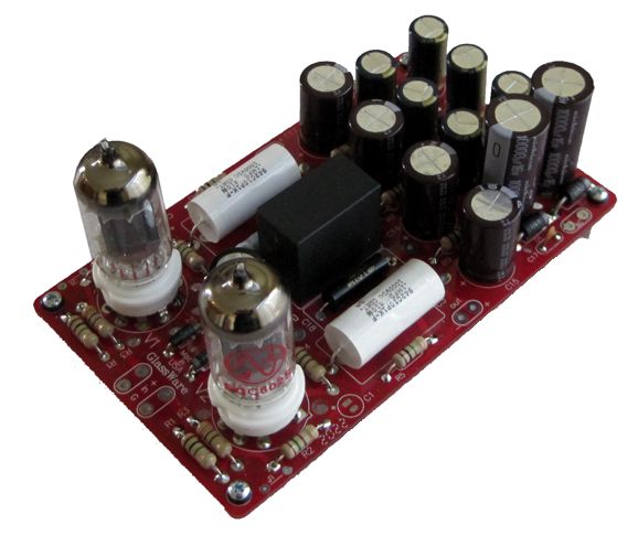
New Design: 12Vac SRPP
Each of us has our high-voltage limit; mine is about 560Vdc, beyond this voltage I get nervous. Others go much further, say 1kV or 2kV. In contrast, I don't even want to breathe next to 2kV. I used to know a fellow who worked on 1,600V voltage panels for a living. He told me that the secret to staying alive was never to show up to work either tired or sleepy. (I remember reading of a hapless man who sneezed while working on a 25kV panel; he was instantly reduced to vapor.) Okay, you get the point: high-voltages are scary, rightfully scary.
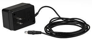
If you live in North America, which includes Canada and Mexico, Jameco offers a 12Vac/2A wallwart for $15. (If you don't know Jameco, you should check them out. I have been buying electronic parts from them since they opened in 1974.)
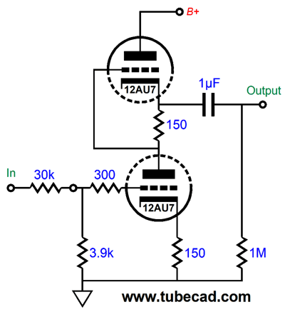
Okay, that explained the 12Vac aspect, but why the SRPP circuit? The SRPP is the world's favorite tube circuit, hands down, no contest. Reasons are not hard to find, such as being super simple and sidestepping the problem of what to do with the other twin triode in the tube envelope—but probably its most appealing feature is that is hard to screw it up.
The grounded-cathode amplifier is not so lucky, as the plate and cathode resistor values must work together with each other and the triode's characteristics. An analogy can be made with a rifle being easier to shoot than a pistol. The pistol requires getting four items in alignment: the target, the front sight, the rear sight, and your eye. On the other hand, the riffle only requires three items: the target, the front sight, and the rear sight and your eye count as one item, as your head rests on you hand and wrist, locking your eye in place relative to the rear sight. With the SRPP circuit, we have only cathode resistors, no plate resistors. By the way, I impose a one-decade statute of limitations on other's big screw ups, where I keep the email and friend's experiences a secret for one tenth of a century before revealing them here. Well about 15 years ago, a reader wrote to me, complaining that a circuit I had posted didn't work. The circuit was just a grounded-cathode amplifier. I asked to see the schematic to his implementation of it. As looked over the scan of a crude drawing, I noted that he must have made typo of sorts, as the cathode resistor value was shown as being something like 3.3Meg, while the plate resistor was 10k. I wrote back asking for clarification. No typo, that's what he used. Why? As every fool knows that part brand is more important, far more important, than part value. He had those resistors in the highly-esteemed brand, so of course, he used them. What was the problem—didn't I understand how high-end audio worked? Apparently not.
An additional SRPP feature, one shared by the Aikido circuit, is that it truly tube-rolling friendly. An SRPP set up for a 12AU7 can easily accept other 12AU7s, such as the ECC802, or altogether different tube types, such as the 12AT7 or 12BH7 or 5963—without having to change cathode resistor values. Speaking of tube types, I designed the 12Vac with four tubes in mind: the 6DJ8, 12AU7, 12BH7, and ECC99. Alas, I had to turn my back on the 6CG7 and 6H30, as their heater draw was excessive. I spent most of yesterday listening to the new 12Vac SRPP with JJ ECC802 (12AU7) tubes. I found the gain more than adequate and sound was captivating. (It often happens that while I am doing sonic evaluation, I become entrapped by the music, unable to break free.) How did the other tube types sound? I don't know, as I didn't try them. In order to try a 12BH7 or ECC99, requires changing two resistor values. These two resistors are in series with the two heater elements. For example, the 12AU7 requires two 20-ohm resistors, while the ECC99 needs two 7.5-ohm resistors. Switching to the 6DJ8, on the other hand, requires changing both the two resistors and two zener diodes. Each heater element is shunted with a zener, which ensure voltage sharing and set a maximum voltage drop across the heater element.
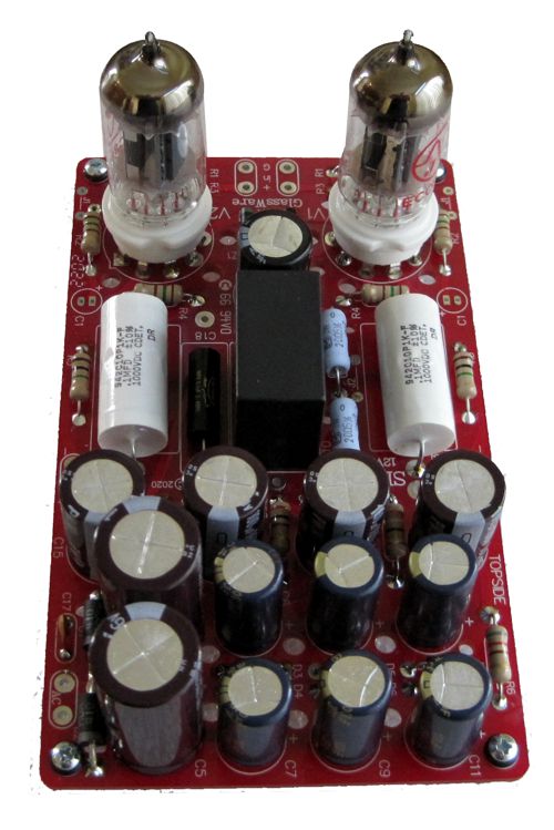
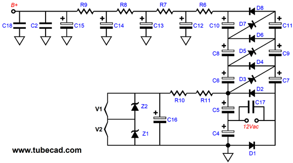
The most interesting part of the design is the on-board power supply. The heaters get DC voltage and the two SRPP circuits get a high-voltage B+ voltage of about 120Vdc. How do you get 120Vdc out 12Vac? A voltage octupler circuit, which uses many rectifiers and capacitors to build up the raw DC voltage of about 130Vdc. If the math seems off, it's due to not realizing that 12Vac actually peaks at 17Vpk, whose average value for a sinewave is 12Vac. But we don't get the full 17Vpk, as we must first subtract the rectifier voltage drop before multiplying by 8. Because the SRPP's PSRR figure is so poor, only -6dB, I included four cascaded RC filters on the B+ voltage. Did it work? Oh yes, indeed. In fact, I could not measure the ripple with my VOM (I will have to try to do so with my scope).
If you look into most modern tuners, CD players, big stand-alone DACs, you see that they are usually embarrassingly empty, especially CD players. Well, into these voids, we can easily fit a 12Vac SRPP PCB. I would either add a small 12Vac toroid power transformer along with the PCB or an isolated power jack on the rear panel, which would allow me to use a 12Vac wallwart transformer. Additionally, I would place a two-resistor voltage divider in front of each SRPP channel, so the SRPP's gain would reduce back to unity. In other words, the attenuators would undo the SRPP gain, so if SRPP realized a gain of 8 (18dB), the attenuator would reduce the input signal to the SRPP by 8.
The two-resistor voltage divider resistor values yield an 8.5-fold reduction in signal level entering the SRPP, which matches the gain a 12AU7 tube delivers. Of course, if you need less or more gain, the attenuator values can be adjusted.
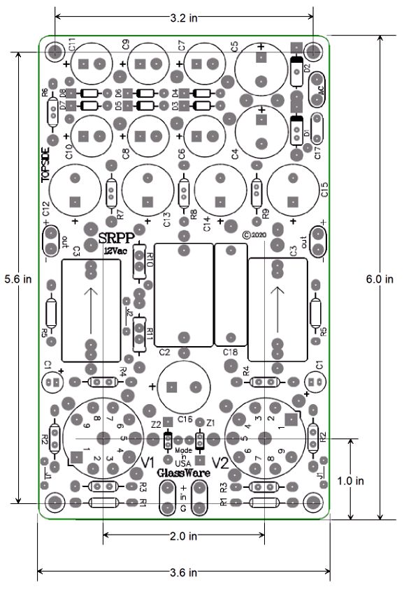
The 12Vac SRPP PCB and part kit is available now at my GlassWare-Yahoo store.
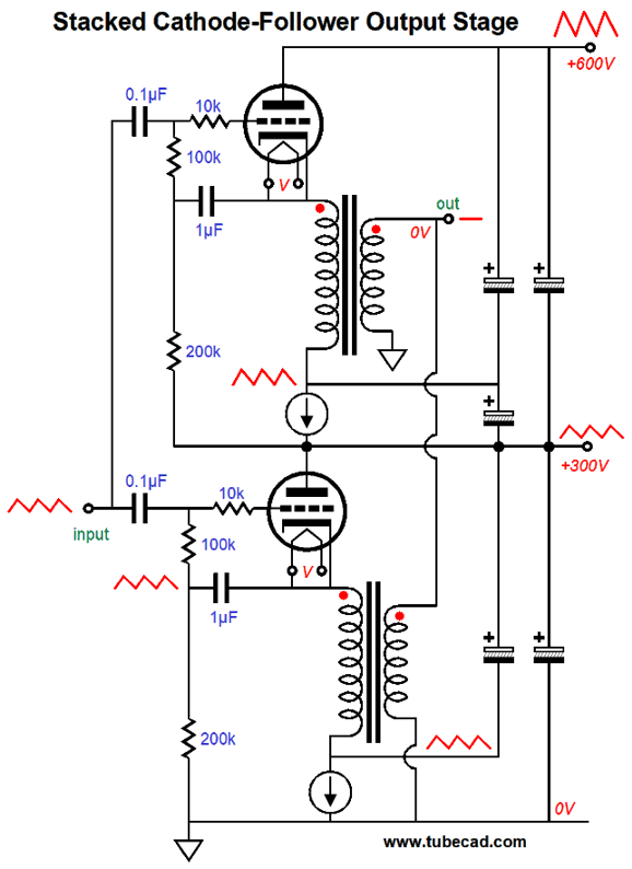
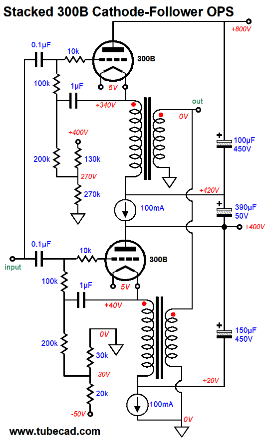
Stacked Cathode-Follower OPS
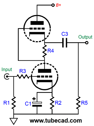
Both cathode-follower output stages would see the same input signal and both would run in phase, so the two output transformer secondaries could be wired in parallel. Thus, we could double the output power. In addition, making the power supply was relatively straightforward. The problem I saw was that each output stage needed to see its own ideal amount of power-supply noise; the top output stage needed to see 50% of the 600V B+ voltage ripple, while the bottom needed to see no power-supply noise. Well, as I looked over the 8-yearold schematics, I realized that we could be even sneakier. (By the way, I like using the words such as "sneaky" and "devious," as they allow me to escape the criticism of overweening pride, if not downright arrogance. Had I resorted to other words, such as "Brilliant" and "Virtuosic," I would have caught grief from overly sensitive types.) What could possibly be sneakier? Well, we could devise a way to submit to both output stages the same signal contaminated with 50% of the higher B+ voltage's ripple. Moreover, such a setup would require using two constant-current sources, which would bestow the added advantage of auto-bias for both output tubes.
Do not pass out, as this is not nearly as complicated as it appears. The bottom output stage is the easiest to understand. The constant-current source is bypass by a large-valued capacitor, but not a capacitor that terminates into ground, rather the capacitor terminates into the output tube's plate and the 300V power-supply connection. Very UltraPathic, don't you think? Effectively what we have done is inject the ripple present at the 300V connection into the bottom of the output transformer's primary, and, in turn, into the output tube's cathode. In other words: if output tube's grid, cathode, and plate all see the same amount of ripple, does it really exist? In terms of output signal to the loudspeaker, it doesn't. As far as the bottom output tube is concerned, it is operating in a noise-free voltage window. The top output stage functions much like the Aikido mojo version of the single-ended, cathode-follower output stage, as the 50% of power-supply noise present at the 300V connection and the top tube's grid effectively cancel, leaving only the 50% of the ripple at the 600V connection. (Only 50%, not 100%, as the 50% at the 300V connection must be subtracted from the 100% at the 600V connection.) All we have to do is make capacitor C1 mu (the triode's amplification factor) times larger in value than capacitor C2. For example, a 300B presents a mu of 3.9, so we could use 390µF for C1 and 100µF for C2. By the way, this signature Aikido mojo technique works best with low-mu triodes. With medium-mu and high-mu triodes, no so much. The result of combing two noise-free output stages, one atop the other, is a single noise-free output for the loudspeaker. So, let us check off our implicit wish list. Low distortion and output impedance; check. Stellar PSRR; check. Twice the power; check. A single input and driver stage for both output stages; check. A better utilization of the available B+ voltage; check. Auto-bias of the output tubes; check. A relatively simple power supply; check. Speaking of the power supply, here is a possible example.
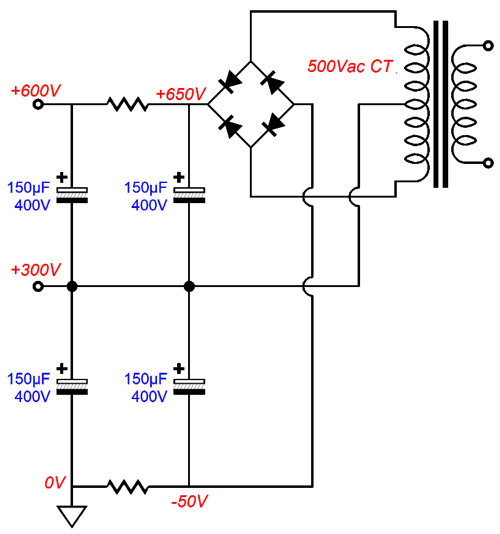
The 500Vac center-tapped primary creates a potential monopolar B+ voltage of 700Vdc or a bipolar power supply with +/-350Vdc rails—or what we see instead above. The absolutely key feature is that the center-tap is not grounded; period. It is floating, i.e. not grounded. The two RC filters clean up the power-supply noise just as well as would a single RC filter with resistor equal two the two RC resistors in series. As a bonus, we have a negative power-supply rail voltage of -50Vdc, which could come in handy with low-mu output triodes, such as the 2A3, 300B, 6AS7, and 845. What is missing are the input and driver stages.
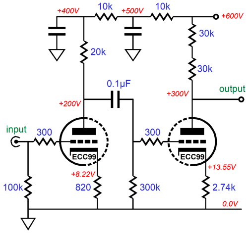
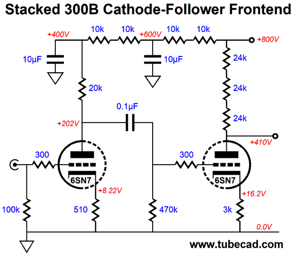
The ECC99 tube is used, as it is robust and it can handle the hot plate voltage. The input stage gets two RC filters, as the input stage must deliver a noise free output. The input stage's relatively high 10mA idle current ensures that the driver stage's Miller-effect capacitance will not prove a hindrance. (Remember that it takes current to quickly charge and discharge a capacitance. If you are unwilling to provide the needed current, expect to hear slow, slew-limited sound.) The driver stage idles at 5mA, and its plate resistor is made up of two 30k resistors in series. Why two resistors? Asides from doubling the wattage, the two resistors in series lower the resistor's voltage-induced distortion, where the resistor's resistance varies slightly with applied voltage drop. With typical solid-state-gear voltages, this is seldom an issue; but with high-voltage designs, it's worth worrying about. In fact, we could use three 20k resistor in series. By the way, if you look up the resistor's datasheet, you will find a voltage-limit rating, which is independent from its wattage rating.
For example, say we have a 1M/1W resistor, which implies a 1kV voltage limit due to its 1W rating, but the resistor's datasheet tells us that 300V is the true voltage limit, beyond which we risk arcing. Well, by placing three resistors in series, we effectively get a 900V voltage limit.
300B Design Example
The assumption here is that 8-ohm loudspeakers will be driven. If 4-ohm types are used, the output must be taken from the two 8-ohm taps instead. The constant-current sources can be made from two LM317 adjustable voltage regulators. As they only dissipate 2W of heat, a small heatsink can be used. In order to get full output, the output transformer primary must see +/-250V peak voltage swings. A more realistic goal would be +/-200V peak voltage swings, which imply an output power of 8W per output stage, a total of 16W into the loudspeaker. In order to develop such huge voltage 200V swings would require that the driver stage put out +/-280V peak voltage swings, something that the 640Vdc B+ voltage and ECC99 driver triode cannot deliver in reality. In the word of SPICE, it can. I have mentioned this before, but it is worth repeating a few dozen times: the SPICE model of the triode is fundamentally flawed. It assumes that the triode is a variable current source. It isn't. A triode on its own cannot create current flow magically. In SPICE, it can. In reality—in sharp contrast—the triode is a variable resistance. A SPICE triode model should return resistance, not current. In addition, it should never return a negative resistance. In other words, the triode is a modified diode that conducts current in only one direction, from negative to positive. If you ever run a SPICE simulation and you see the plate voltage swing below the cathode voltage, you have got a problem. If the plate voltage were actually below the cathode voltage, no current would flow. In short, the quick back-of-an-envelope calculations are fine, as are SPICE simulations, but they are likely to overshoot reality. Okay, what would reality look like? The ECC99's plate-voltage limit is 400V, whereas the 6SN7's is 450V. Thus, we will use the 6SN7. Here are the input and driver stages.
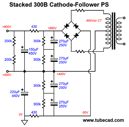
Yes, that is a scary B+ voltage. Some system of staggered turn-on should be implemented; for example, a good start would be heating the heater elements and filaments first, before slamming on the B+ voltage. The 20k resistors should be made from two 10k 2W resistors in series. The driver stage's 72k plate resistor requires three 24k resistors in series. The RC capacitors should be rated for at least 800Vdc. In SPICE simulations, the amplifier's frontend delivered a gain of 105, requiring an input signal of 2.7Vpk for full output. Because of the extremely high voltages, the power supply must be a bit more complicated than the one shown previously.
The sweet spot for high-voltage electrolytic capacitors is 250V, as this is the voltage rating that offers the most variety and capacitance per dollar. When we place two power-supply capacitors in series, we must shunt each capacitor with a bleeder resistor to force an equal voltage division between capacitors.
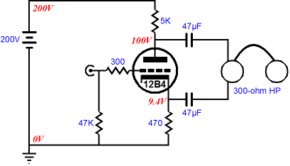
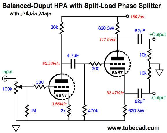
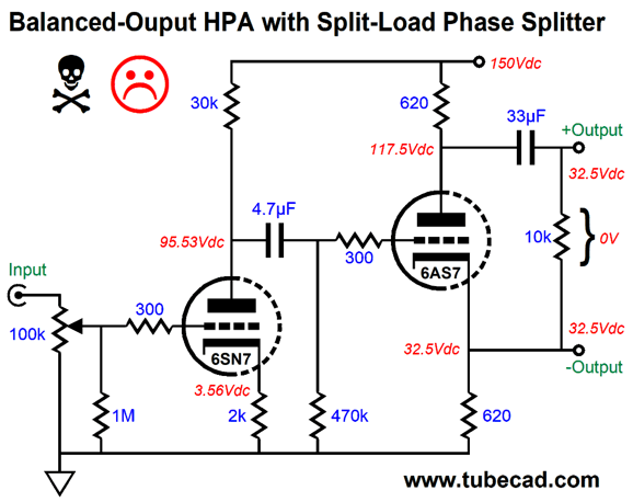
Balanced Output
One way to look at it is that a split-load phase splitter is actually one half of a circlotron output stage—or, that the circlotron is two split-load phase splitters wired together. The circlotron output impedance is equal to Zo = rp/(mu + 2), assuming class-A operation; once the output stage leaves class-A and enters class-B, it rises to Zo = 2rp/(mu + 2). See post 167 for more details. With a 6AS7 and 620-ohm cathode and plate resistors, we can expect an output impedance of about 110 ohms, which would work well with 300-ohm headphones. The idle current will be about 50mA.
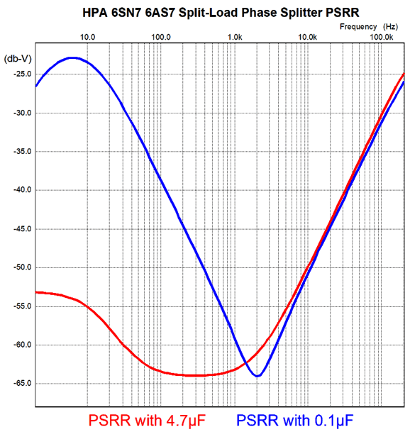
I tried to keep as many of the original part values as possible. The internal coupling capacitor value of 4.7µF may seem crazy large, but here is the logic behind its big value. This circuit embodies Aikido mojo, as the differential output is stunningly noise-free, the result of carefully ensuring that the input stage delivers the right amount of power-supply noise to the split-load phase splitter triode's grid. In order for the deep PSRR null to extend below 100Hz require very little phase shift at low frequencies, which the large-valued coupling capacitor ensures.
Of course, 1µF would be far better than 0.1µF, and a regulated B+ voltage would be ideal. The output coupling capacitors seem to be twice as large as they need to be for low-frequency bandwidth down to 20Hz with a 300-ohm load impedance. And they would be, if we were not running a differential output stage. Effectively the two coupling capacitors are in series, so the combined capacitance is half that of each capacitor; thus, the need for twice as big capacitors.
If you were willing to live dangerously, you could use only one output coupling capacitor; not recommended. For example, if only the top output coupling capacitor were used, both connections to the headphone driver would carry the same 32.5Vdc voltage. The headphone would ignore this voltage, as the headphone driver is an intrinsically differential device that only responds to voltage differences, while ignoring voltage commonalities. Relative to ground, however, 32.5V DC voltage would cause a big spark if it encountered a ground-referenced item. Since the headphone driver is enclosed and the wires are sheathed, how likely is this to occur? I don't know, nor do I wish to find out. Remember that they called Murphy an optimist.
Yes, it is the current that kills you, but the current only flows because of the voltage. I remember reading that the 48Vdc open circuit voltage of telephone land-lines was chosen as 48vdc was deemed safe enough. Interestingly, most desktop switcher power supplies top out at either 48Vdc or 54Vdc. Think about this: we never want an electric current to flow through our heart or brain. (This explains why I always place an arm behind me when I measure extremely high voltages or wear rubber gloves. The last thing you want to be doing is grabbing the chassis.) I have also read that the body's resistance is about 600 ohms. (Fortunately, I have extremely dry skin.) If we divide 48V by 600 ohms we get 80mA, a scary amount of current. Well, since headphones rest upon our heads, and since our ears can sweat, I would not feel safe with 32.5Vdc being near my head. Once again, remember that they called Murphy an optimist. As a teenager, I read in the newspaper about an unfortunate fellow who liked to watch a portable TV set on his chest while he reposed on his waterbed—until the day his cat slashed his bed and he and the TV instantly sank into the water. At the time, I also owned a waterbed and a Panasonic portable (battery-powered) TV, but no cat. Had I own a cat, you probably wouldn't be reading this.
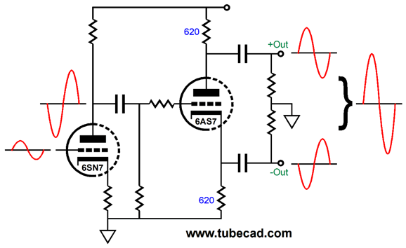
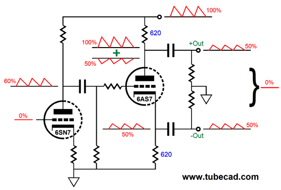
Here we see the signal relationships. Note that the 6SN7 must deliver more signal to the 6AS7 than we will get at the output. Here are the B+ ripple relationships.
Two conditions will yield no power-supply noise from the headphones: the power supply is absolutely noise-free; both output phases hold the same amount of in-phase power-supply noise. In this example, they both hold 50% of the power-supply noise. With the split-load phase splitter, this was the only ratio possible.
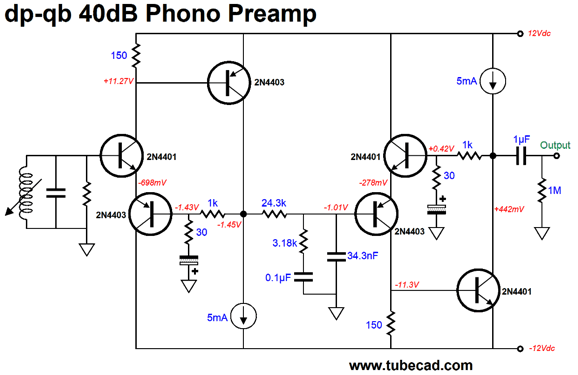
DP-QB Cascade
Well, this topology prompted me to remember a phono preamp design I came up with long ago, but failed to show here.
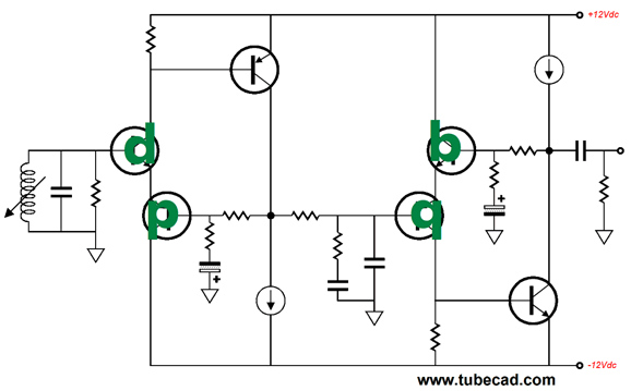
This preamp consists of two cascaded 30dB gain stages, with a passive equalization network in between. Note the progress from NPN to PNP to PNP to NPN transistors. Also note the DC voltage shifts from 0V to -0.7V to -1.43 to -1.01V to -0.278V to +0.42V. If you are still wondering where the name, "dp-qb," comes from, this following image should make it clear.
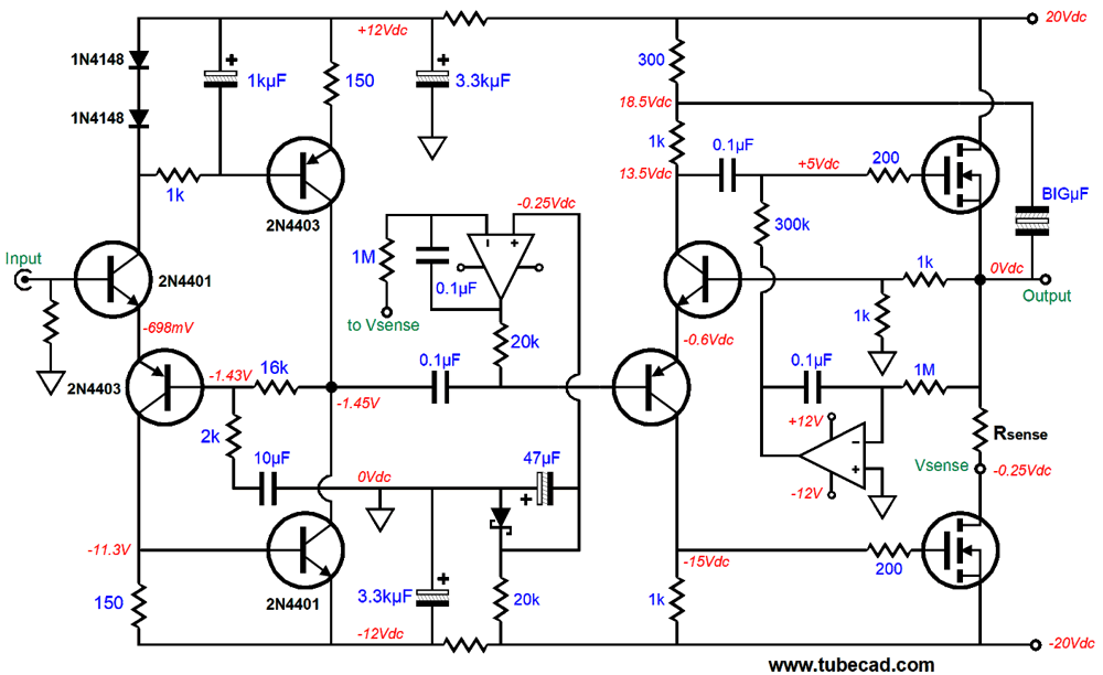
Okay, now let's look a two-stage power amplifier based on the same cascade of bastode input st ages.
The first amplifier gain stage delivers a gain of 9, while the output gain stage yields a gain of 2, making for a total gain of 18. The output half of the amplifier can work with the bipolar power supply and not require additional higher rail voltages because of its gain of 2. Lower or higher gain would not work. Why so? The bastode transistors must both swing down 9V without hitting the bottom MOSFET's gate voltage or have the NPN collector voltage choke off the 1k collector resistor's bottom voltage. By the way, the output stage must be run in class-A, as the auto-bias DC servo requires it. Another by-the-way, this design falls into the category of "selfless amplifiers," which is a joke that only four people will get.
Music Recommendation: Kathleen Grace with Larry Goldings
This is a country album in the best sense of classic country, not the modern slick country, but an older, more Western America country music, an offshoot of old American folk music. Hank Williams would approve. I will admit that at first, I was disappointed, as I wanted to hear an album more like Tie Me To You, but three minutes later I was won over. She sings with such heartfelt sincerity that genre doesn't matter, and her middle name should be "FilledWith." So far, I have listened to it twice and I enjoyed more the second time. A very good sign. (I would love to hear this album on vinyl or high-res Flac.) Well, I had to find more of her albums, but only these two were listed. I then searched the web and discovered that she sang on nine of the thirteen tracks of the album, We All Love Burt Bacharach, by Massimo Colombo, an Italian pianist.
Another recent discovery I made was of Morgan James, apparently she is one of those many famous people I never heard of, as she is an accomplished songwriter, singer, and Broadway actress.
Note the speaker. That alone should pique your interest. Next, one of her albums is named OurVinyl Sessions should double your interest. All of this piqued mine. Her cover of The Beatles' White Album won me over, against my extreme prejudice, as I easily imagined a cringe-inducing kitsch of an album. Not so. In fact, I am sure that Ringo and Paul would give it a big thumbs up.
Other than both singers being unknown to me a week ago, what do the two have in common other than great voices? Blonde hair? Naked feet? Both having done covers of Beatles songs? No, I found both well represented at Tidal and Amazon Music, with Amazon offering more choices. Tidal needs to catch up and then move ahead.
//JRB
User Guides for GlassWare Software
For those of you who still have old computers running Windows XP (32-bit) or any other Windows 32-bit OS, I have setup the download availability of my old old standards: Tube CAD, SE Amp CAD, and Audio Gadgets. The downloads are at the GlassWare-Yahoo store and the price is only $9.95 for each program. http://glass-ware.stores.yahoo.net/adsoffromgla.html So many have asked that I had to do it. WARNING: THESE THREE PROGRAMS WILL NOT RUN UNDER VISTA 64-Bit or WINDOWS 7 & 8 or any other 64-bit OS. I do plan on remaking all of these programs into 64-bit versions, but it will be a huge ordeal, as programming requires vast chunks of noise-free time, something very rare with children running about. Ideally, I would love to come out with versions that run on iPads and Android-OS tablets.
|
I know that some readers wish to avoid Patreon, so here is a PayPal button instead. Thanks. John Broskie
John Gives
Special Thanks to the Special 81 To all my patrons, all 81 of them, thank you all again. I want to especially thank
I am truly stunned and appreciative of their support. In addition I want to thank the following patrons:
All of your support makes a big difference. I would love to arrive at the point where creating my posts was my top priority of the day, not something that I have to steal time from other obligations to do. The more support I get, the higher up these posts move up in deserving attention.
If you have been reading my posts, you know that my lifetime goal is reaching post number one thousand. I have 495 more to go. My second goal was to gather 1,000 patrons. Well, that no longer seems possible to me, so I will shoot for a mighty 100 instead. Thus, I have 19 patrons to go. Help me get there.
Support the Tube CAD Journal & get an extremely powerful push-pull tube-amplifier simulator for TCJ Push-Pull Calculator
TCJ PPC Version 2 Improvements Rebuilt simulation engine *User definable
Download or CD ROM For more information, please visit our Web site : To purchase, please visit our Yahoo Store: |
|||


| www.tubecad.com Copyright © 1999-2020 GlassWare All Rights Reserved |