| John Broskie's Guide to Tube Circuit Analysis & Design |
Letter from Enro Borbely 29 Nov 2002 Dear Editor,
It is an honor to meet you, even if it is over the net. I have read all your articles in Audio Amateur and I have enjoyed and learned from them greatly. Twenty years ago, I even built a pair of your 60 watt MOSFET amplifiers for a friend (very nice sounding; we used a 400 VA toroidal power transformer). A thousand apologies to Rudolf. I have built a complex I-to-V converter based on his design, which worked quite well. The sincerest-form-of-complement version of your
circuit is popular and I bet it must madden you to see someone else
spoil your design and make money by doing so. But then, I am not the
one ask about circuit design ownership or patenting, as I am not sure
that patenting of topologies should be allowed anymore than I believe
sentence structure should be copyrightable. Now, using your name would
be an altogether different case and thus we can see the genius of Ray
Dolby copyrighting the name, not the circuit. (I have been told that
some of the remakes of famous amplifiers which were printed in this
journal have been faithfully implemented — without
any credit to me, of course.) In general, I believe designs and topologies
are not as valued as much as is hype. I just read in a business book
at the bookstore yesterday that many people make the mistake of putting
90% of their effort into creating a better product and only 10% into
marketing, rather than inverting the ratio! This philosophy sickens
me, but it is probably closer to success than I wish to acknowledge.
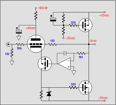
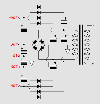
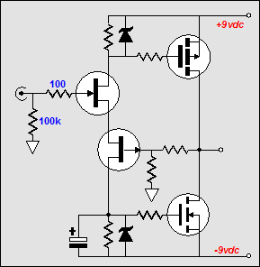
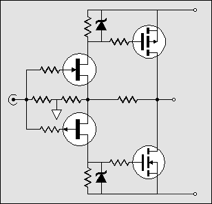
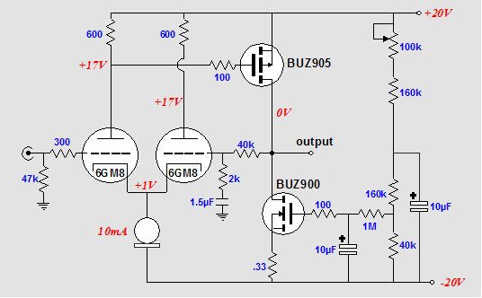
As for your design, I am glad to see someone using the 6GM8. (I wish there were more grid-frame tubes.) Below is the circuit I would try to build today, if I had the time. The advantages of DC coupling are retained and the higher rail voltage for the tube could easily be derived with the voltage tippler circuit I outlined in the that issue of the Tube CAD Journal you received. As for the headphone amplifier, I bet the FETs are much more quiet. About a year ago, I received a schematic and two pairs of matched FETs from a kind reader. The simplest HP amp possible: 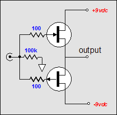 It works quite well; the IDSS is about 10 mA and it sounds great with 300-ohm headphones. (If only there were some P-channel depletion-mode MOSFETs.) If 32-ohm headphones need to be driven, then the following circuits might be better choices.
More email on Erno’s amplifier topology
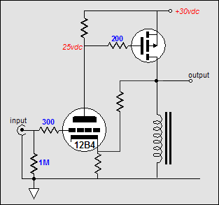
In all honesty, I cannot recommend building any variation of the circuit that was stolen from Erno Borbely (visit www.borbelyaudio.com). The two tricks that made the circuit attractive are low plate voltage and direct coupling. The problem, however, with the circuit is low plate voltage and direct coupling. The low plate voltage is incompatible with low distortion and the direct coupling is incompatible with safety, as at startup, huge DC offsets are likely. My recommendation is to build an amp that uses a separate high-voltage PS for the tubes and AC couple the tube to the MOSFET. Alternatively, you might experiment with a simpler version of the original circuit, one that forgoes using the current mirror. Below is a DC coupled amplifier that might prove safer, if the time constants are set to match the tube’s delay in heating up. But a better plan might be to use a more elaborate scheme wherein the output will not slam negatively when the tube fails or is removed from the powered circuit. In the circuit below, the bottom MOSFET relies on the tube to be conducting to energize its auto-bias circuit. If the triode is pulled out of its socket, the top transistor stops conducting and the bottom MOSFET loses its turn-on voltage. 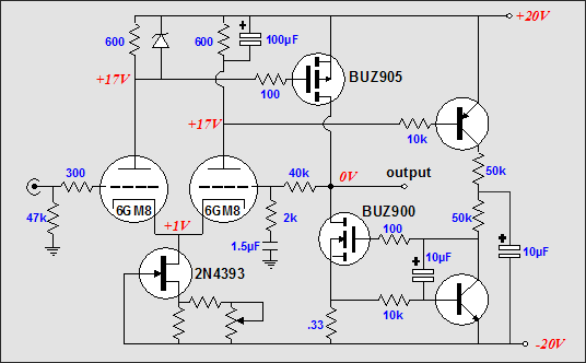
The simplest and possibly the best plan might be to do away with the active constant current source altogether and use an inductive load instead, as the efficiency of the amplifier will double and the amplifier will not destroy your speakers, if the tube is jiggled or removed from its socket. (If the choke’s DCR is higher than a third of an ohm, a coupling capacitor might be needed at the output.)
The end //JRB |
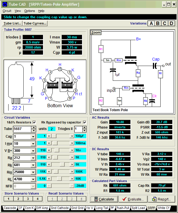
Tube CAD does the hard math for you. This program covers 13 types of tube circuits, each one divided into four variations: 52 circuits in all. Tube CAD calculates the noteworthy results, such as gain, phase, output impedance, low frequency cutoff, PSRR, bias voltage, plate and load resistor heat dissipations. Which tube gives the most gain? Tube CAD's scenario comparison feature shows which tube wins. Windows 95/98/Me/NT/2000/XP For more information, please visit our Web site :
|
|||


| www.tubecad.com Copyright © 1999-2004 GlassWare All Rights Reserved |