| John Broskie's Guide to Tube Circuit Analysis & Design |
|
||||
24 November 2004 32-ohm speaker design
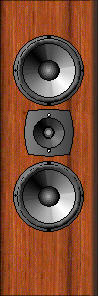
Now, let’s do some easy math. Since each speaker driver receives only one half of the output voltage swing, each driver will be down –6 dB compared to what a single driver would put out. If we started with 86-dB-efficient loudspeakers, we will be down to 80 dB. Do not lose heart. Since we have doubled the driver area, the system efficiency goes up by +6 dB, to 86 dB. That’s right: we took a giant step sideways. If we started with 86-dB-efficient loudspeakers we end up with 86-dB-efficient loudspeakers, but a loudspeaker that can more efficiently extract the wattage latent in the 6AS7s. (Do not worry about the Qts going up as result, as the Qes does not go up with the impedance and the Qms remains constant.) But what about the tweeter? Who makes a 32-ohm tweeter? No one does, as far as I know. But we do not have to use a 32-ohm tweeter—we can use a 8-ohm tweeter. Here’s how: if we use a 98-dB efficient tweeter and place a 24-ohm resistor in series with it, the effective efficiency drops by –12dB, as the driver now only sees one quarter of the output voltage swing. Once again, we are now back to 86 dB efficiency. Are not 98-dB efficient tweeters rare? Not if you like horns. If the tweeter is too efficient, then additional padding can be added. (An added advantage to the horn tweeter is that helps to time align the woofers to the tweeter, as its voice coil is located about 2 inches behind its horn’s end.) The high-frequency crossover capacitors will only be one fourth the value that an 8-ohm speaker would demand, but the inductor values will be four times greater. The down side to the horn tweeter is that—aside from them not being everyone’s cup of tea—is that a good one can be quite expensive. The easy way out is to not use a tweeter and use full-range drivers exclusively. However, finding a 16-ohm fullrange may be difficult; whereas finding an 8-ohm fullrange is painless. At about $15 each, the Tang Band W3-879S 3" shielded driver come readily to mind. Or for $10 each, the Pioneer A11EC80-02f 4-1/2" driver can be had. I haven't looked, but I'm sure that Radio Shack and MCM also sell suitable drivers. What sort of enclosure could we use? The answer of course depends on the drivers selected, but something narrow and tall would take up less desk space.
Next time, the amplifier design. //JRB
Tube-based computer amplifier Because we sit close to the loudspeakers, small loudspeakers powered by an equally small amplifier are all that is needed. And such small systems, albeit solid-state systems, are readily bought. But have you heard them? I have searched out the highly rated systems and I was appalled—tweeters and subwoofer but no midrange was all I heard. Yes, they are cheap and attractive in their plastic sort of way, but I would not like to listen to them for eight hours a day. More to my liking would be some wood and glass and more midrange. How to proceed? The obvious and easy solution is to build a simple hybrid amplifier that either holds an IC input and driver circuit that feeds a pair of high-transconductance output tubes (such as the EL84s) or a tube-input-driver circuit that feeds a pair of power MOSFETs or power IC amplifier. Each alternative holds much promise and a fairly low cost. (And either amplifier might serve double duty as a small bedroom amplifier.) The first approach uses two Op-Amps to provide all the voltage gain and phase splitting needed to drive the output tubes to full output—if the Op-Amps can provide the needed voltage swing that is. Most audio Op-Amps can only tolerate ±18 to ±22-volt power supply rails and can only swing between 16- to 20-volt peaks, not enough for most power tubes, even the grid effective EL84s. One workaround is to use high-voltage Op-Amps, but these are rare and expensive. A better workaround is to cross couple the outputs. The schematic bellows shows how: 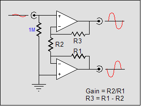
Above, we see two Op-Amps define an unbalanced-to-balance converter, while also providing voltage gain. Below, we see how the two output tubes connect to the Op-Amps. Notice that each output tube has its own cathode resistor to bias the itself and that each tube receives its drive voltage from the opposing Op-Amp’s output, which effectively doubles the drive signal into each output tube. Thus, our ± 20-volt output swing becomes ± 38-volts. 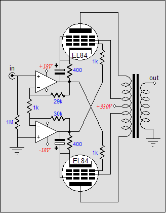
To forestall any e-mails pointing out that little Op-Amps cannot source 50mA of continuous current, the following schematic shows how to boost the output current capability of the Op-Amps. 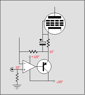
By the way, fixed bias can easily be implemented as well, as shown below. 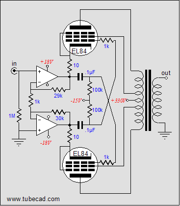
The output transformer is available from Triode Electronics Online for only $59 each (and if they are only half as good as the original Z565 output transformer used in the Dynaco ST-35 and SCA-35 amplifiers, they’ll be twice as desirable as the alternative from Hammond, in my opinion). The B+ transformer is just a 240-volt toroidal or conventional stacked-frame transformer that are commonly available. Which Op-Amp to use? What does your budget allow. AD712s could be used or two separate OPA-604 s (or even two AD825s) could also be used. Remember start cheap and work your way up. As for power transistors, I would use MJE340s, but only because I own too many of them already. I will not bother showing any tube-to-MOSFET hybrid amplifiers, as I have covered several already in these pages. (Still, if I were building this sort of amplifier, I would search out the roundest, tallest extruded heatsinks to take the visual place of the missing output tubes.) The third way Stop and think about this: all OTL amplifiers are current limited; they cannot deliver a hefty enough current to match their huge voltage swings. For example, into a 1k load, the Futterman amplifier can deliver 100-volts of peak swing, which if deliverable into an 8-ohm load would equal 625 watts! In contrast, all solid-state amplifiers are voltage limited; they cannot deliver a high enough voltage to match their huge potential current swings. Into a 1-ohm load, the typical 100-watt solid-state amplifier can easily deliver 12.5-amperes of peak current swing (of course, the fuse will blow), which if deliverable into an 8-ohm load would equal 625 watts! Actually, in the typical solid-state amplifier, the power transformer is the greater limitation on current delivery, as the output stage could deliver an easy 100A into a dead short, which would equal 40,000 watts into an 8-ohm load. On the other hand, the power supply is not the problem in a tube OTL amplifier; the tubes themselves are, as they cannot deliver nearly the current that their solid-state brethren can. Thus, tube OTL amplifiers are greatly handicapped by the low impedance presented by most loudspeakers, as even large, many-tubed, OTL amplifiers are hard pressed to put out 4 amperes of current. On the other hand, if we owned a 25-ohm loudspeaker, the same OTL amplifier could deliver 200 watts, instead of only 60 watts into 8 ohms and 30 watts into 4 ohms. Here we can see the brilliance behind an output transformer; like the car’s the transmission, it conforms to the presented load. With a well-designed transformer-coupled tube amplifier, both the maximum potential voltage and current is delivered into the load. Thus, the 16-, 8-, and 4-ohm taps to retranslate the available voltage and current swings into the specified load impedance; unlike a solid-state amplifier, these amplifiers do not double their output wattage into a 4-ohm load, nor lose half of their output wattage into a 16-ohm load. Well then, why not build a high-impedance loudspeaker to work with a small OTL amplifier that only used two 6AS7s per channel? Such an amplifier would not too egregiously overheat our rooms and it would certainly prove a great conversation piece. Optimal load 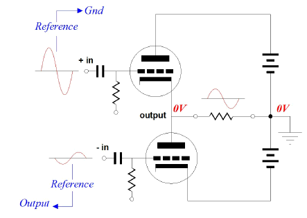
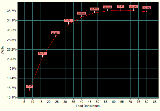
The key variables are: an OTL output stage configured with cathode-follower operation for top and bottom triodes, two pairs of 6AS7 triodes (a total of two 6AS7 envelopes), 165 volts of B+ voltage, and an idle current of 50mA per triode (the input signal level will be automatically adjusted by the program for each simulation—how cool is that; can you believe that there are readers who haven’t bought this program; if I hadn’t created it, I would have been first in line to buy it). Below we see the results from a array of ten simulations starting at 8 ohms and ending at 80 ohms.
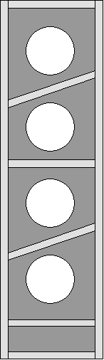
The optimal value is 64 ohms, which is a little discouraging. (PDF of array results.)We could use more output tubes, but I wanted something simple and small. Yet, if we look into the data, we see that 32 ohms was only off by 11% of the wattage delivered into 64 ohms. Not too bad and much better (220%) than the 15 watts deliverable into 8 ohms. Still, where do we buy a 32-ohm loudspeaker. We don’t—we build one. The easiest way would be to buy four cheap 8-ohm loudspeakers and stack them together, with all the connections in series like an old Christmas-tree light set. (I actually once heard this setup with four very-expensive, mini-monitor loudspeakers per channel, with two facing forward, one facing to the side and one facing backwards. How did it sound? Fantastic. Shockingly good, in fact.) Alternatively, we can build a small, but tall speaker that holds four full-range 8-ohm drivers or two 16-ohm drivers. This is the path I would like to follow. (Back, when I was high-school student in the 70s, my brother and I built a simple dipole with four 5-inch Philips full-range drivers and one backward firing tweeter (8kHz and above). How did it sound? Fantastic. Shockingly good, in fact. One drug-addled friend said it was the best sounding speaker he had ever heard.) Let me stop right here, so that this idea can be pondered for a while. The next step will be the speaker design and then the amplifier circuit. //JRB
|
TCJ My-Stock DB
TCJ My-Stock DB helps you know just what you have, what it looks like, where it is, what it will be used for, and what it's worth. TCJ My-Stock DB helps you to keep track of your heap of electronic parts. More details. Version 2 Improvements *User definable Download or CD ROM |
|||


| www.tubecad.com Copyright © 1999-2004 GlassWare All Rights Reserved |