| John Broskie's Guide to Tube Circuit Analysis & Design |
|
21 August 2017 Post 392
Special Thanks If you have been reading my posts, you know that my lifetime goal is reaching post number one thousand. I have 608 more to go. With only eight more to go, I should easily be able to hit post 400 this year. My second goal is to gather 1,000 patrons. I have 952 patrons to go. If you enjoyed reading this post from me for the last 18 years, then you might consider becoming one of my patrons at Patreon.com. It would make a big difference to me. Thanks.
Dealing with DACs
I was just about to bring up Rene Descartes and mind-body dualism, but then I remembered that I already did that back in post 70. (My father once told me that the best thing about getting so old that your memory fades is that you then can re-read your favorite novels, without knowing what will happen next.) Well, before I knew what exactly lay hidden in the Chromecast audio puck, I had come up with a bunch of tube-based circuits for use following a DAC, particularly those DACs that present a voltage output and big DC offset. I planned on both presenting these circuits in an upcoming post and using one of them with one of my Chromecast audio pucks, as I was about to break one open to see what was inside.
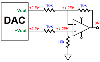
Once I discovered (through some web searching), however, that the Chromecast Audio puck held a both a DAC and a line driver IC that used charge-pumps to create their own negative-power-supply rails, I abandoned these circuits, as no DC offsets existed —a mistake that. Why? Many DACs do present a large DC offset at their voltage output (often balanced outputs), usually equal to half of the DAC's analog power-supply voltage, usually 3.3Vdc or 5Vdc, so the offset voltage is usually 1.65Vdc or 2.5Vdc. Most importantly, most high-end DACs are of this type. The Chromecast Audio puck is a lot of fun and a great value, but it does not hold a flagship DAC. The usual way to deal with DC offsets encountered with DACs that present balanced, voltage outputs is to use an OpAmp configured as a differential amplifier, as shown below.
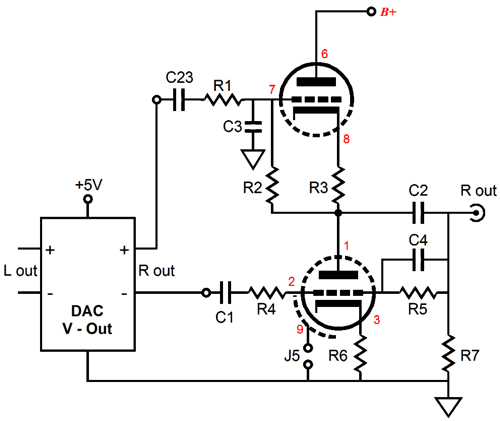
The DC offset is treated as a common-mode signal and ignored. Impressive, no? (By the way, the critical part of getting a differential amplifier to perform seeming magic is to ensure that the two input signals offer identical impedances and that the differential amplifier's resistors match. If they don't, the high CMRR dwindles away, which is why you will see 0.1% tolerance resistors specified.) With tube circuits, however, we will be using coupling capacitor(s), so the DC offset only becomes a problem for the tube circuit's input stage. How much of a problem? It depends on the circuit and the tubes used. For example, a 12AX7 would overheat, if its grid saw an unexpected +2.5DC on its grid. In contrast, a 6AS7 might barely shift up its idle current. The obvious solution is to use input coupling capacitors, as shown in the BCF schematic below.
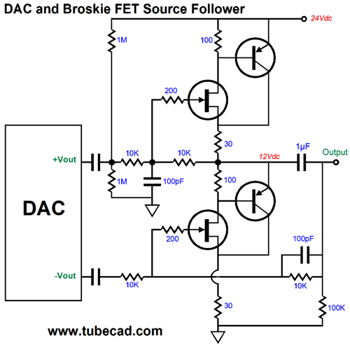
By the way, we can translate the above circuit into solid-state, as shown below.
Before going any further, it's always a good question to ask if this trip is really necessary. If the DAC is already putting out analog signal in the form of low-impedance voltage, a relatively hot signal at that, so why not just stop here? One day, no doubt, we will be able to stop here, but not today. Today, the only way the high-end DACs achieve their stellar signal-to-noise ratios and ultra-low distortion figures is by presenting a balanced output signal, so that the differential sum is pure. One signal output on its own, isn't nearly so stellar. In other words, even if we seek a single-ended output, the DAC's balanced output must travel through a differential amplifier of some sort, as the high-frequency power-supply noise must be stripped away.
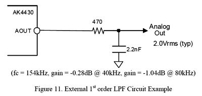
One possibility is a high-quality isolation transformer. Every passing year, I grow to appreciate signal transformers more and more. They solve some otherwise unsolvable problems. With a high-quality isolation transformer, the DC offset and common-mode noise problem vanish. (Or maybe the high-frequency noise problem doesn't completely vanish, as one of the reasons that 1:1 isolation transformers offer so little distortion and high-frequency bandwidth is that they cheat. The primary-to-secondary capacitance effectively becomes a coupling capacitor of sorts. In other words, the high-frequency hash might still get through.) The next issue to tackle is post high-frequency filtering, even though just about all DACs hold some form of digital low-pass filtering. Many skip this step, however, as many emails to me have revealed. The voltage-out signal comes out the DAC and goes into an SRPP circuit—over and over and over again. Is this a bad idea or practice? Here comes the answer most hated by audiophiles: It depends. For example, if the output from the SRPP feeds a tube power amplifier with high-frequency bandwidth out to only 30kHz, probably not, as who cares what is going on at 200kHz. On the other hand, if the power amplifier is some wiz-bang design that aims for less than 0.1 degree of phase shift at 20kHz and whose -3dB frequency is in the megahertz, probably not a good idea. Ideally, we should have user selectable post filtering. The post filtering can be as little as one series resistor and one capacitor to ground. Here is an example from the AK4430 data sheet.
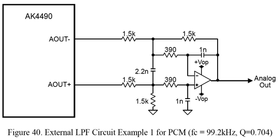
This the DAC used in the Chromecast Audio puck; this is a fine 24-bit DAC, but not the company's flagship model by any means. Or, the post filtering can be as complex as the following circuit, which was taken form the AK4490's data sheet.
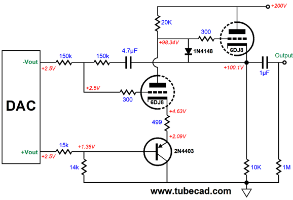
I have seen many variations on this scheme—but all were OpAmp-based, so I went to work on a tube-based version. Let's warm up with a hybrid version.
The DAC's DC offset is no longer a liability, as it has become an asset. The leftmost triode and the 2N4403 PNP transistor define a differential amplifier, with rather good CMRR, made even larger by the use of the 14k resistor at the transistor's base. This slightly smaller valued resistor reduces the cathode gain to that of the grid. (The grid offers an amplification factor of mu, while the cathode presents a slightly higher mu, equal to mu + 1, which is why "mu + 1" appears in so many tube formulas. With a high-mu triode, such as the 5751 and 12AX7, we often ignore this difference; with a low-mu triode, such as the 6AS7 or 845, it is crucial.) The 10k & 12k resistors set the gain to 2, or +6dB. In other words, if the DAC puts outs a balanced signal of +0.1Vpk and -0.1Vpk, then the cathode follower will put out +0.2Vpk. Or, you can view the gain as being unity, as the differential difference between the balanced signals is 0.2Vpk. Now that we have our basic circuit, we need to impose the low-pass filtering. Two extra resistors and three added capacitors is all it took.
Note the 47µF internal coupling capacitor. SPICE simulations revealed that at least this value was required to ensure a good CMRR at low frequencies. The circuit's frequency plots reveals a smooth cutoff, one quite similar that offered by the solid-state OpAmp version.
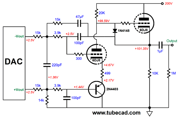
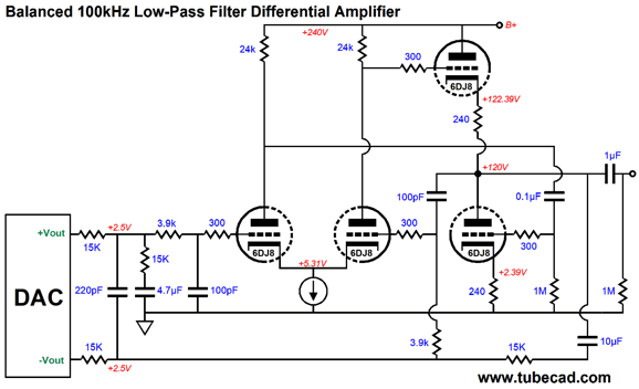
Another approach would be to let the input stage do all the straight differential amplification and let the cathode follower do all the low-pass filtering by configuring it as a 2nd-order low-pass filter.
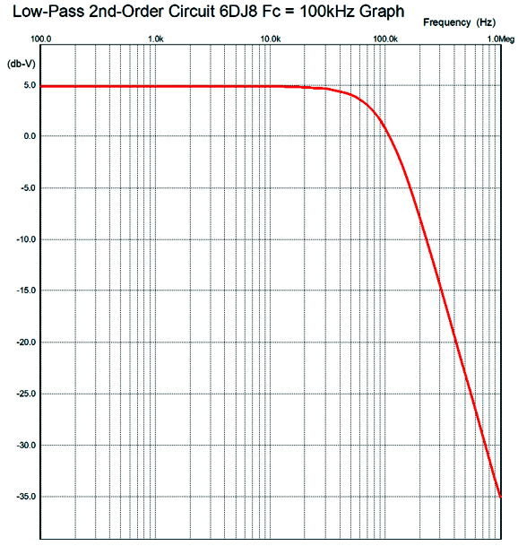
Note that I altered the resistor values that feed the leftmost 6DJ8 its signal, so a smaller-valued capacitor could be used. The rightmost 6DJ8 is in charge of the low-pass filtering. The two-to-one ratio of filter capacitors defines a Butterworth alignment. For a Bessel alignment, we would use 180pF and 140pF capacitors. In either case, we end up with a second-order slope. Actually, it starts out as a second-order, -12dB slope, low-pass filter, but it slope steepens above 6ookHz.
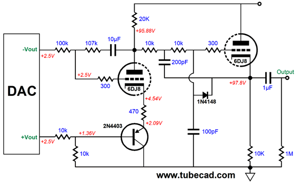
And, yes, we could incorporate low-pass filtering in both stages, resulting in an even steeper slope. On the other hand, if we are willing to use coupling capacitors, we can simply use a Broskie cathode follower circuit.
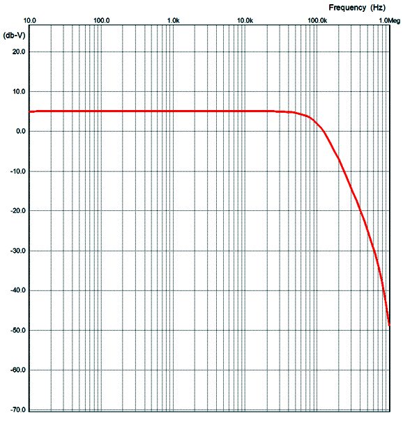
No extra gain and a 2nd-order low-pass filtering are offered by the above circuit, as shown below.
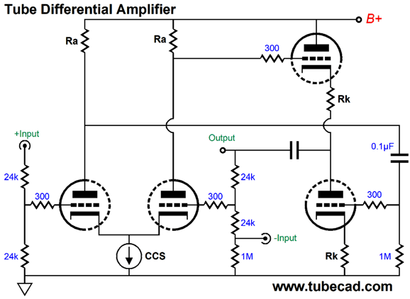
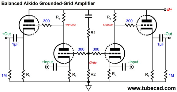
If we are willing to use two tubes, i.e. four triodes in two tube envelopes, many more topologies present themselves. For example, here is a tube-based differential amplifier.
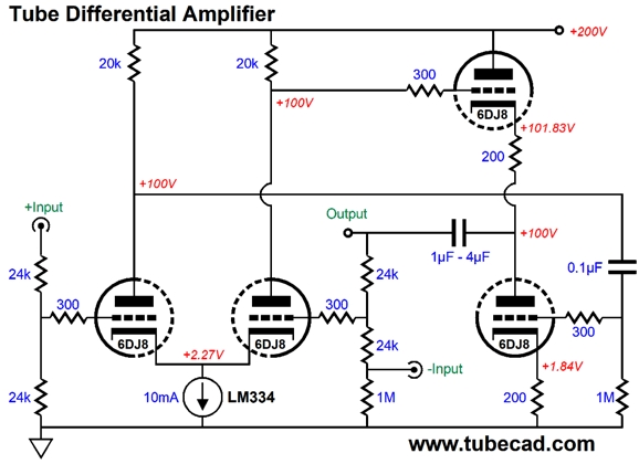
A balanced input goes in and an unbalanced output emerges. This circuit works quite well and can exhibit a CMRR of at least -60dB and low distortion with a decidedly single-ended flavor. Here it again, but a bit more fleshed out.
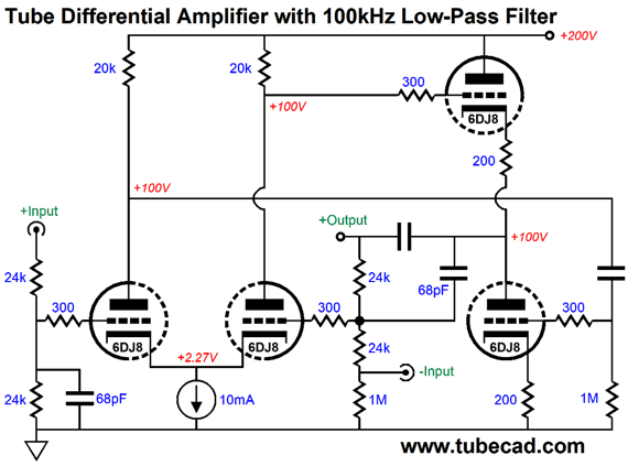
Of course, different tubes and a higher or lower B+ voltage could be used, but this is the configuration upon which I ran SPICE simulations. Adding some low-pass filtering is easy enough.
One problem with this circuit is that any balanced signal source that presents a DC offset will unbalance the input stage and create a DC offset at the output. One workaround is the following variation that gladly accepts the DC offset and presents no offset at its output, while delivering a steeper filtering slope.
The DC offset is absorbed by the constant-current source cathode loading of the input tube. Note the required large-valued capacitors. Up to now, all the circuits delivered an unbalanced output. This might be a mistake, as providing the option of either unbalanced or balanced does not require much more work.
Balanced Outputs
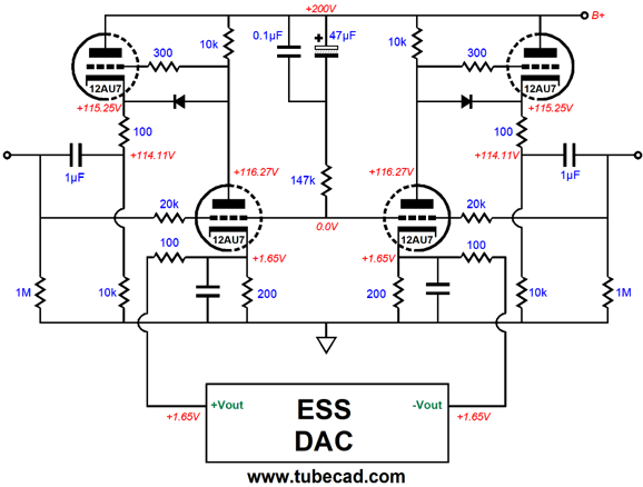
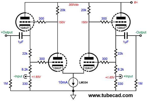
By carefully selecting part values and operating points, we can lose the input coupling capacitors.
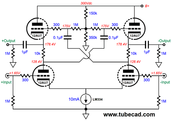
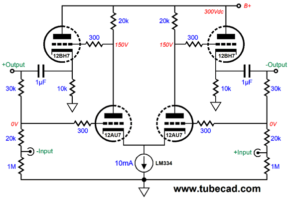
The two 20k and the one 147k resistors work to ensure good balance and fine PSRR. One problem, however, might be too much gain. Unlike current-out DACs, voltage-out DACs seldom need much gain. The following two designs deliver much lower gain.
The low gain results from the each pair of top and bottom triodes working in current phase, not out of phase, which greatly reduces the gain. If we un-crisscross where the 0.1µF capacitors terminate, then each vertical pair of triode would work in anti-current phase, which would greatly increase the gain, where the gain would top out at the bottom triode's amplification factor. By the way, as it stands, no post high-frequency filtering is employed; thus, this circuit could be used as aplain line-stage amplifier. The next circuit tickles me much. It uses the cathode follower's load resistors as negative-feedback resistors for the bottom triodes global feedback loops.
Feel free to scratch your head for a minute or two. Perhaps, I should have shown the following schematic first, so as to prepare your mind.
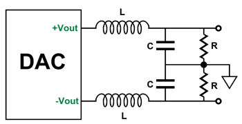
It is still a bit confusing, as I am using the negative-feedback resistors to DC terminate the output coupling capacitors, thereby getting dual use out of them. Nonetheless, the idea behind the circuit is simple enough: two inverting amplifiers have been arranged differentially. The inner two triodes control the cathode follower triodes. The gain is set by the ratio between the 30k and 20k negative-feedback resistors. Adding some high-frequency post filtering could be as easy as adding shunting capacitors to the 30k negative-feedback resistors. But such a setup would only impose a first-order filter slope. One idea that has been buzzing in my head for the last 30 years is that CD players and standalone DAC units could both use some inductors. I like the idea of using passive, LCR, filters to do the high-frequency post filtering. Why? Passive filters offer many advantages at high-frequencies, such as proving effective at high-frequencies beyond the limits of most OpAmps. In addition, they add no new noise and they do not easily overload or latch up or lose their minds the way that an OpAmp can. Here is what I had in mind.
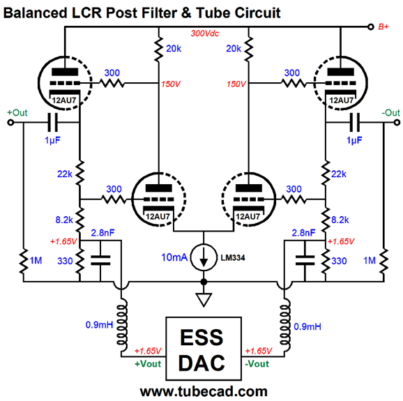
We can apply either a Butterworth or Bessel or Gaussian or Linkwitz-Riley filter alignment. The one big problem is R in the LCR filter. If its value is too big, so,too, will be the inductor's value. If it is too small, then the DAC will be burdened and forced to source heavy DC current into the resistor should the DAC's output presents a DC offset. The following circuit eliminates the last problem by having the tubes source the DC current flow through the resistor, so the DAC doesn't have to do so.
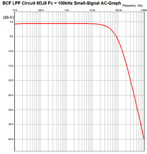
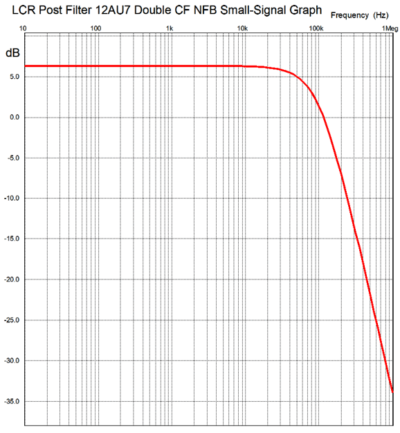
These LCR values create a Bessel, 2nd-order, 100kHz low-pass filter. Here is the SPICE generated frequency plot for the entire circuit.
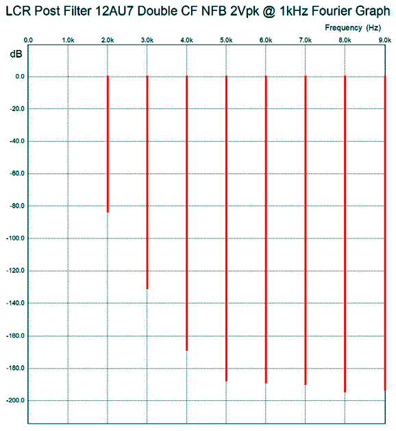
And here is the Fourier breakdown of the distortion harmonics at 2Vpk output at 1kHz.
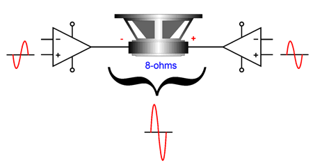
Even if reality is ten times worse, i.e. we add +20dB to each harmonic, this is great stuff, the stuff that audiophile dreams are made of. Note the wonderfully single-ended cascade of harmonics. The output impedance at each output is about 250 ohms. That's great, John, but I only run unbalanced amplifiers. You can use balanced outs with unbalanced amplifiers; it's no big deal, just add two RCA jacks per channel, then label one positive and the other negative. Choose either RCA jack to plug your unbalanced amplifier into. No big deal. Indeed, having the two polarities output allows us to do some fun things, such as run separate amplifiers for sub woofers or create a bridge amplifier out of an existing stereo amplifier.
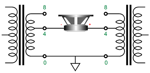
This arrangement will double the wattage that the amplifier can deliver into a 4-ohm load. For example, if the power amplifier can deliver 50W into 8-ohm loads and 100W into 4-ohm loads, then if it is arranged in this setup with an 8-ohm loudspeaker, the power delivered will be 200W. Yes, 200W. Each amplifier thinks it is working into a 4-ohm load, so it delivers 100W; and since there are two power amplifiers, the wattages add together. On the other hand, if the 50W amplifier can only deliver 80W into 4-ohm loads, we only get 160W in this arrangement. Two caveats: if you own 4-ohm loudspeakers or if you own tube OTL power amplifiers, don't try this trick; and if you own transformer-coupled tube power amplifier, only expect twice the nominal power output, not four times more. Why? The solid-state power amplifier is voltage limited; the transformer-coupled tube power amplifier, current limited. This bridge arrangement allows more voltage swing into the speaker, with two solid-state power amplifier, but does not allow twice the current swing from tube amplifiers. Here is how to attach the 8-ohm speaker to two tube-based, transformer-coupled power amplifiers.
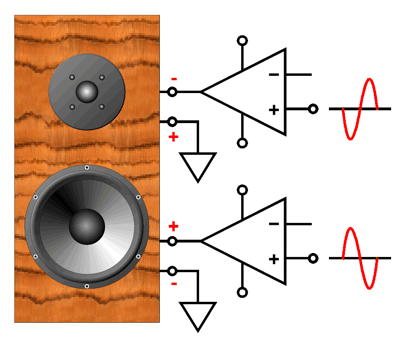
Another possible use for the two anti-phase outputs is to use one stereo amplifier with a bi-wired loudspeaker. In other words, we will give the woofer and tweeter its own power amplifier, but leave the existing internal crossovers in place.
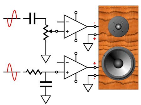
Note the phase reversal on the tweeter's bi-wire terminals. As it stands, this arrangement does not seem to buy us much, as each driver will see the same maximum wattage as before. True enough, but if we remove the attenuation padding resistors from the tweeter, the amplifier that feeds the tweeter will effectively become much bigger in power output. For example, if the tweeter's SPL is 94dB at 1W at 1 meter and the woofer's SPL is 88dB, then the tweeter must get a -6dB attenuator padding, consisting of an 8-ohm resistor in parallel with the tweeter and a 4-ohm resistor in series with the tweeter, which results in the tweeter seeing half the voltage that the woofer sees. Well, twice the voltage means four times the watts, as Wattage = Voltage²/Resistance. Triple the voltage and you get nine times more watts. In other words, a nominally 25W amplifier would now seem equal to a 100W amplifier to the tweeter in this example. Okay, what happens if we add some filtering? For example, say the two-way loudspeaker crossover frequency is 3kHz. I would apply a 6kHz low-pass filter to the amplifier that feeds the woofer and a 1.5kHz high-pass filter to the amplifier that feeds the tweeter. I actually did just this forty years ago, while I was a college student. I used the low-frequency amplifier's own negative feedback compensation capacitor to set the 6kHz transition frequency and I added an input coupling capacitor to the high-frequency power amplifier. Fifteen minutes of soldering and few extra parts and I was ready to go. The result was that my two 20W solid-state stereo power amplifiers sounded vastly more powerful, as the tweeter amplifier seldom clipped, whereas the woofer amplifier clipped all the time—but I could not hear it.
Of course, if you are paranoid about phase shifts ruining the loudspeaker crossover functioning, you could use 12kHz and 750Hz as the cut-off frequencies instead. Combine this arrangement with the removal of the tweeters resistor padding and you will be thrilled by the bigger sound. Because the tweeter still sees its internal crossover, it is safe in this arrangement. In contrast, many tweeters have fried in bi-ampped systems due to hum or loose connectors and thumps and bumps and buzzes burning out the tweeter. //JRB
User Guides for GlassWare Software
For those of you who still have old computers running Windows XP (32-bit) or any other Windows 32-bit OS, I have setup the download availability of my old old standards: Tube CAD, SE Amp CAD, and Audio Gadgets. The downloads are at the GlassWare-Yahoo store and the price is only $9.95 for each program. http://glass-ware.stores.yahoo.net/adsoffromgla.html So many have asked that I had to do it. WARNING: THESE THREE PROGRAMS WILL NOT RUN UNDER VISTA 64-Bit or WINDOWS 7 & 8 or any other 64-bit OS. I do plan on remaking all of these programs into 64-bit versions, but it will be a huge ordeal, as programming requires vast chunks of noise-free time, something very rare with children running about. Ideally, I would love to come out with versions that run on iPads and Android-OS tablets.
//JRB
|
|
Kit User Guide PDFs
Only $12.95 TCJ My-Stock DB
Version 2 Improvements *User definable Download for www.glass-ware.com |
||


.png)


| www.tubecad.com Copyright © 1999-2017 GlassWare All Rights Reserved |