| John Broskie's Guide to Tube Circuit Analysis & Design |
|
19 April 2017 Post 377
Nelson Pass & Amplifier Philosophy At the same time, not all audio distortions are equal. Alfred North Whitehead taught at Harvard; one day a student told him that he hadn't deserved the "A" he had received, as most of what he wrote was bull. To which Whitehead replied,
What we desire is the right sort of distortion. I remember John Curl pointing out that 2nd and 3rd harmonics were relatively benign,* whereas 5th and higher odd harmonics grated our ears. Back in 1992, Nelson Pass wrote an essay title, Asymmetric—The Purest Class A. (I have hunted the web for a link to this paper, but I could not find one. Here is a link to the closest alternative that I could find.) He began in a section titled "Philosophy,"
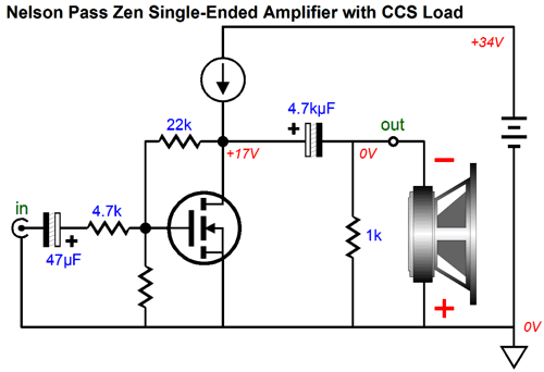
Verily. He went to state that air itself was an audio component and that its characteristics, its own non-linearity, should be mimicked by audio amplifiers, as this would produce the most natural sound. Thus, he argued that only a single-ended, class-A amplifier should be used, as a push-pull output stage, even a class-A one, would deliver a too symmetric—a too linear—output. He ended his paper by pointing that tubes and MOSFETs, but not transistors, most closely resembled the non-linearity of air in their transconductance curves. This brings up an interesting possibility: a triode run under constant-current may not bend enough; it might deliver a too symmetric—a too linear—output. 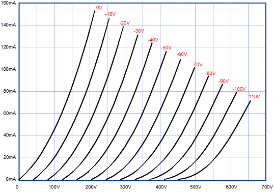
Draw horizontal line at 80mA and note the equal spacing between lines. With a load-line in place, the non-linearity would be obvious. In other words, the Super-Triode concept might not deliver enough of the right sort of distortion. In this case, we might have to load down the triode with an internal load resistance. Here is an example of a linear super-triode output stage. 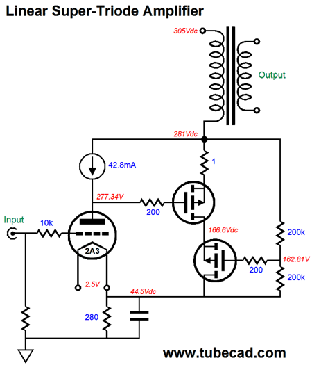
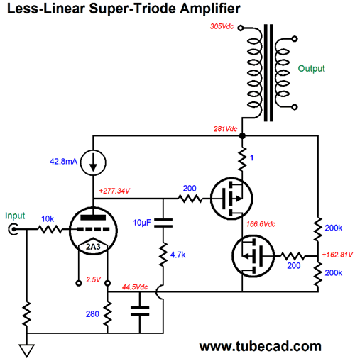
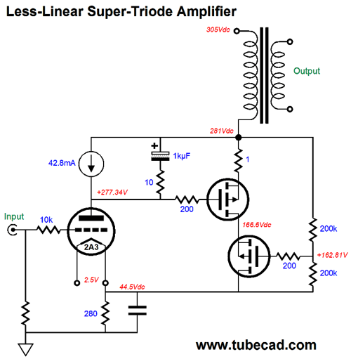
Note how both the triode's and MOSFET's idle current are set by the single 280-ohm cathode/drain resistor. This super-triode output stage is intrinsically linear, as the triode operates under a constant-current flow, as in fixed, stable, static, steady, unchanging, and unvarying. If the 2A3's grid sees a positive voltage, its plate voltage must drop by the 2A3's amplification factor in order to maintain the fixed current flow of 42.8mA. In other words, the load-line is equal to infinity, as the plate voltage swings a horizontal line across the triode's plate curves. Forcing some non-linearity is fairly easy, as the following schematic shows.
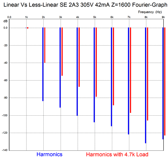
The difference is the 10µF capacitor and the 4.7k resistor. Adding these two parts means that the triode no longer operates under a constant-current flow; instead, its current flow will vary with the input signal, which will subtract from the super linearity. How much so? Here are the harmonics for 7.5W of output, without and with the added 4.7k load resistor.
With the added load resistance, the THD is about 1%; without it, 0.01%. Note the same single-ended flavor of the harmonics. Thus, both would sound similar, with the loaded version sounding more ripe, more warm. Which is better? You choose. Which is better Italian or Thai food? You choose. No one else can. Of course, we could replace the 4.7k resistor with a higher or lower value. Indeed, we could use a selector switch to choose between an array of load resistances. Why not use a potentiometer? Heat and power. The 4.7k resistor will dissipate 2.5W at full output (7.5W), which is plenty hot. I would use 10W resistor at the lower resistor values and 3W resistors at the high end of resistances. Is there no way we can use the power wasted in the load resistor to drive the speaker instead? Indeed. The easy way is to place the resistor and capacitor across the constant-current source.
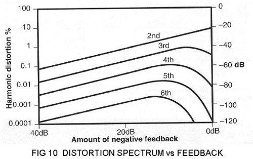
Note the 10-ohm resistance and the 1kµF capacitor value. These added parts shunt the constant-current source and greatly reduce the super-triode effect, with a resulting drop in linearity. Returning to the philosophical question of whether low THD figures mean anything useful to an audiophile, Jan Didden wrote a fine article, titled, "Feedback—Curse or Blessing?" for Audio Electronics in their sixth issue of 1997. Like all the articles Jan has written, this one is a pleasure to read and should be reread a few times. Jan include Peter Baxandall famous distortion graph, shown below.
Note how 2nd harmonic goes down linearly with feedback, but all the higher order harmonics first go up and then fall with increased feedback. Didden spells it out nicely,
Then in June of 2000, Anthony New contributed an excellent article to Electronics World titled, "THD is Meaningless." His argument was that intermodulation distortion (IMD) was far worse and that the problem with THD figures was that all harmonics were weighted equally, which was insane as most could not hear 1% of 2nd harmonic distortion, while 1% of 7th harmonic would pearce your ears like an ice pick. .
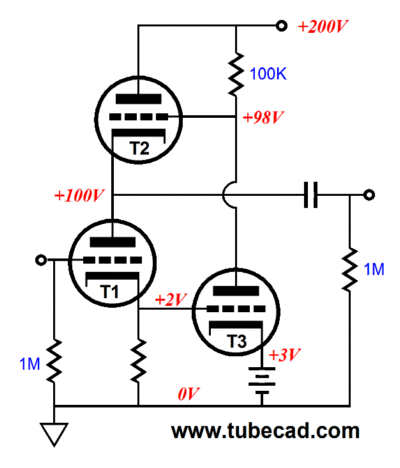
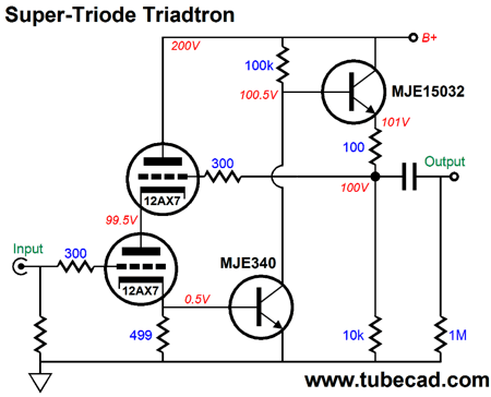
Super-Triode versus Triadtron The following schematic show three triodes in a Triadtron arrangement. Triode T1 draws a constant current, while triode T2 sees a varying current flow. Triode T1 is in charge. If T1 draws less current, triode T3 sees the increase in T1's cathode voltage and T3 draws more current, which pulls down T3's plate voltage, causing T2's cathode voltage to also drop, bringing T1 back into constant-current conduction.
Conversely, if T1 draws more current, triode T3 sees the decrease in T1's cathode voltage and T3 draws less current, which releases T3's grip on its plate resistor, causing its plate voltage to rise, which in turn forces T2's cathode voltage to also increase, once again, bringing T1 back into constant-current conduction. Since triode T1 is the star, it should be a high-quality triode, such as the 2A3 or 300B or 845. Triode T3 should be a low-current, high-mu triode, such as the 12AX7 or 12AT7 or 5751 or 6072. Triode T3 can be the same type as T1 or a lessor quality tube, such as a 6AS7 or 6BQ5 (EL84) or 6L6 or 6550. Indeed, triodes T2 and T3 need not be tubes, as either or both can be replaced by MOSFETs or transistors. The following triadtron replaces triode T2 with an N-channel MOSFET.
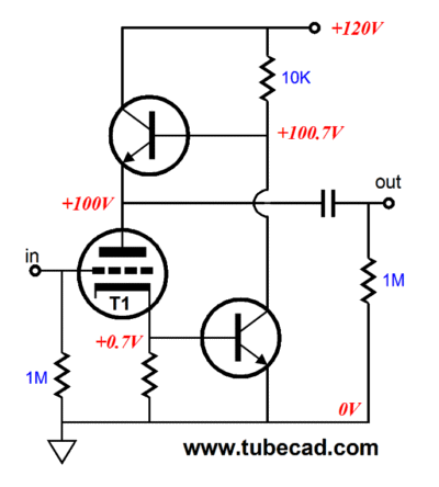
The next example uses two NPN transistors.
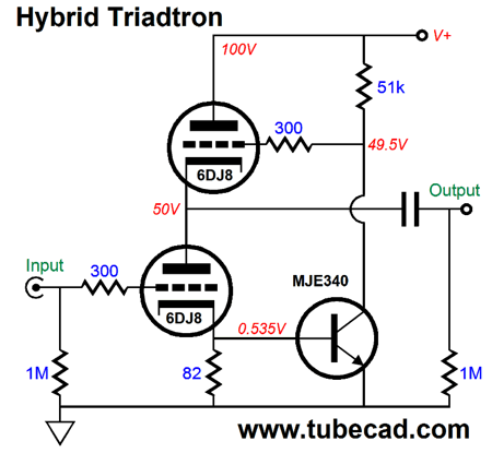
In both examples, triode T1 draws a nearly constant current, while the device at its plate varies its current conduction in response to input signals. The difference between top and bottom conduction is delivered into the external load impedance. In short, the triadtron's starring output device both functions as a constant-current source and as the controlling active device. In contrast, the super-triode arrangement's starring triode only functions as the controlling active device. Which is better? It depends, the answer most hated by tube-newbies. The triadtron is more efficient, as the controlling triode's current conduction is put to good use. Of course, this sort of efficiency is far more important in a power amplifier than it is in a line-stage amplifier, such as the following design.
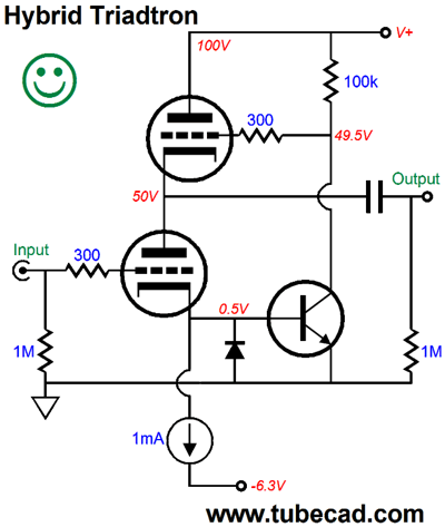
Note the low B+ voltage of only 100V. Both triode experience an idle current of 6.5ma, but only the top 6DJ8 triode sees a varying current flow. This circuit yields a gain equal to the 6DJ8's mu, or about 31. The distortion is low and consists mostly of 2nd harmonic product. The output impedance is staggeringly low, a tad less than 7 ohms. The PSRR is about -30dB. If we replace the 51k collector resistor with a 1mA constant-current source, the PSRR improves to -60dB and the Zo halves, while the distortion remains largely unchanged. What if we replace both the 51k and 82-ohm resistors with constant-current sources? The PSRR improves dramatically and the output impedance falls to about 1 ohm. Unfortunately, we cannot get a solid-state constant-current source to work within a 0.5V window; not enough voltage differential. One workaround is to use a negative power-supply rail, as shown below.
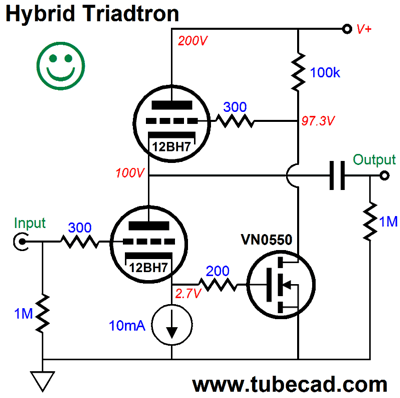
Another possibility is to use a higher B+ voltage and a different triode and use a MOSFET instead of a bipolar transistor.
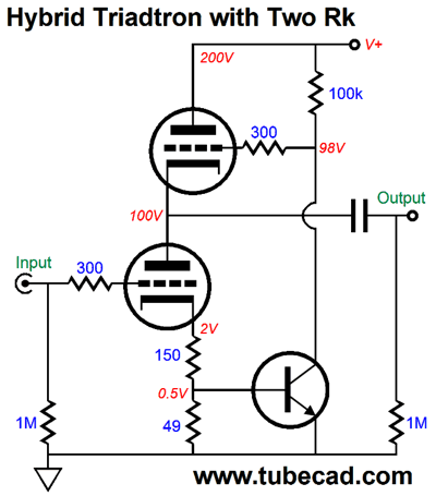
We can use two cathode resistors with a transistor, however, as shown below.
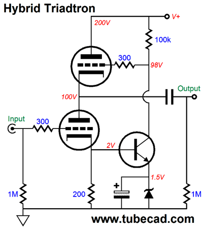
The 150-cathode resistor can be bypassed by a large-valued capacitor. Another arrangement is the following.
The zener (or two diodes in series) allows us to develop 2V across the cathode resistor. Still another possibility is to use a high-mu triode, such as the 12AX7. The higher the mu, the lower the cathode voltage will be.
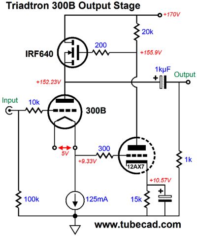
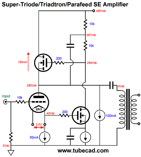
The above circuit weds the triadtron to the super-triode concept. The triodes do not drive the external load, but they do control the output signal. This circuit offers a gain roughly equal to the triode's mu, which in this case nears 100 (or +40dB), which would make this circuit useful in a phono stage or a microphone preamp. Making a power amplifier out of this topology requires a bit of fiddling.
There is so much going on in the above schematic that I am not sure where to start. Note that the 100mA constant-current source is in parallel with the 2A3. The triode does not drive the output transformer's primary at all, as the 2A3 draws a constant current; instead, the top MOSFET and the 100mA constant-current source do all the hard work. Unlike previous super-triode designs, this circuit does not burden the primary with wasted current flow from the triode. The output power will equal the 100mA squared against one half the primary impedance. For example, if the primary impedance is 3k, then 0.1²(3,000/2) = 15W. Well, that's the theory; reality differs, as 100mA against 3k equals a peak voltage swing of 300V, which would not be possible with just a 480V B+ voltage and the 290V plate voltage. A quick formula for finding the peak negative current swing is Vpeak = Rload x Vb/(rp + Rload) Thus, with a 2A3's rp of 800 ohms and a primary impedance of 3k and a cathode-to-plate voltage of 248V, we get a peak negative voltage swing of 196V. If we upped the B+ voltage to 500V, then the peak positive voltage swing could match the negative swing, resulting in about 6.5W of power into the speaker. With the 480V B+ voltage, a higher constant-current-source idle current and a lower primary impedance would yield far more power output. On the other hand, if the 100mA constant-current source were removed, the peak output current swing would equal the triode's idle current of 50mA, which into a 3k primary would equal 3.75W of output power.
Next Time
//JRB
* John Curl Video
If you have been reading my posts, you know that my lifetime goal is reaching post number one thousand. I have 623 more to go. My second goal is to gather 1,000 patrons. I have 965 patrons to go. If I were a betting-man, I would place my bet on reaching the 1,000 patron goal first, as I have a hard time believing that I have already posted 371 times. How is that possible? I would never have bet on that happening. If you enjoyed reading this post from me, then you might consider becoming one of my patrons at Patreon.com.
Next Time
User Guides for GlassWare Software
For those of you who still have old computers running Windows XP (32-bit) or any other Windows 32-bit OS, I have setup the download availability of my old old standards: Tube CAD, SE Amp CAD, and Audio Gadgets. The downloads are at the GlassWare-Yahoo store and the price is only $9.95 for each program. http://glass-ware.stores.yahoo.net/adsoffromgla.html So many have asked that I had to do it. WARNING: THESE THREE PROGRAMS WILL NOT RUN UNDER VISTA 64-Bit or WINDOWS 7 & 8 or any other 64-bit OS. I do plan on remaking all of these programs into 64-bit versions, but it will be a huge ordeal, as programming requires vast chunks of noise-free time, something very rare with children running about. Ideally, I would love to come out with versions that run on iPads and Android-OS tablets.
//JRB
|
|
Kit User Guide PDFs
Only $12.95 TCJ My-Stock DB
Version 2 Improvements *User definable Download for www.glass-ware.com |
||


| www.tubecad.com Copyright © 1999-2017 GlassWare All Rights Reserved |