| John Broskie's Guide to Tube Circuit Analysis & Design |
25 March 2017 Post Number 375
In Praise of Old Magazines
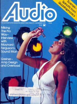
When you are only twenty years old, the possible is still possible. You just might learn Latin or read War and Peace or rebuild that old Heathkit power amplifier; with each passing decade, however, the possibilities dwindle and, finally, end with your end. Moreover, magazines were created for the moment, not for eternity. A five-month-old Time magazine not only bores, it irks. Thus, the thought arose in my mind that—rather than open the box and store its magazines—I should drop the unopened box in the recycle bin. I couldn't do it. Instead, I dutifully carried the hefty box downstairs and opened it. I picked up the topmost magazine, an issue of Audio magazine from November 1977.
I remembered the cover and remembered not liking it back in 1977. (She looks like she is about to place a medical device in her mouth, not sing. In addition, if you are not going to adorn the cover with a piece of audio equipment, opting instead for babe appeal, then you must pick a more flattering photo. I am sure that this young woman was far more attractive than the photographer was able to capture. She was obviously a "deep winter," but the sky-blue background clashed, being better suited for a "light-winter" skin and hair coloring, Elisabeth Taylor for example; a better background color for this model would have been navy blue or fuchsia.) I was beginning to regret not visiting the recycle bin after all. Nonetheless, I quickly flipped through its pages and I found on page 82 this interesting schematic for the Lux MB-3045 Power Amplifier.
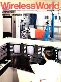
Note the power triodes in the output stage, which were custom-made for Lux; in addition, note all the tertiary windings, A & B & C & D. The review offers a good explanation of its operation, by the way. My own review, 40 years later, is that the two 22µF capacitors that attach to the tertiary winding (D), which feeds the two internal negative feedback loops, could be eliminated, if this winding's center-tap were left floating and some care was taken in assuring DC balance in the differential driver stage. In this same issue, we find an interesting article on amplifier design and overload by R. A. Greiner. In other words, I am not about to commit this issue to the recycle bin. As I unloaded the magazines, I discovered an out-of-place issue of Wireless World magazine from February of 1972, whose cover I did not recognize.
The pages had browned and I gave it fast perusal. Dang. It looked fascinating, so I saved it for that day's late-night reading. In the Letters to the Editor section, I found a gem titled "In praise of horn loudspeakers." Here's a portion of it:
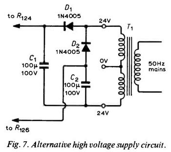
I loved every word of it, including "the," "in," and "to." Note his qualification within double negation: "not entirely unrequited." A not altogether unpleasant sentence to read. And I loved reading this sentence, "It is obvious that hornloading of an loudspeaker motor produces virtues of many sorts and that the end product assumes a grandeur — there is no other term possible — which no other method seems capable of emulating." Bravo and dang right he is. (I have been a closet horn-lover for almost 50 years. I owned a single Klipsch corner horn in high school, which I used as a subwoofer. But that was before I entered the horn closet.) You will find Mr Telfer's entire letter at the bottom of this page. I also found the following schematic of a voltage doubler power supply.
What pleased me most was that it read from right to left, with the AC on the right and the final DC on the left, which is my strong preference for drawing power supplies. Why? Just as amplifier schematic begins at the left, with the signal growing bigger and dirtier as it moves to the right, this orientation of a power supply goes from clean DC to ragged DC and then AC. Then on page 86, I found this wonderful description of the equalization applied to LPs:
Nicely put. I particularly like "passing through a point of inflection at 1kHz." In the same article, titled, Circards-5: Audio Circuits, Pre -amps, mixers, filters and tone controls, we find a new proposed classification for loudspeakers:
So, if you are ever inclined to build a seven-way speaker system, with a 15in (10Hz to 30Hz) and 12in (30Hz to 100Hz) and 10in (100Hz to 300Hz) and 6in (300Hz to 1kHz) and 5in (1kHz to 3kHz) and 2in (3kHz to 10kHz) and 1in (10kHz to 30kHz) drivers, you will have a ready list names for each driver. (I have seen mid-ranges called squawkers, which seems far less dignified that "crooner.") This article also contains the following jewel:
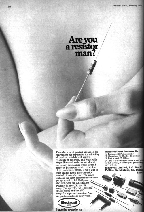
Mercy. How is it possible not to be an anglophile? But my biggest surprise was found on page 102.
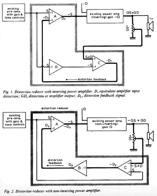
Imagine the outrage, the shrieks and howls, such an ad would provoke in our prissy, over-sensitive, and enfeebled era. Those were the days, when men were men and when you could say "Are you a resistor man," rather than "resistor person." A lovely hand, by the way. All in all, the ad was a delicious bit of British understatement and reserve. Don't think so? Well, imagine the same ad made by Americans or Brazilians of the 1970s. In addition, this issue held an interesting article by D. Bollen on a technique that lowers your existing power amplifiers distortion, both THD and IM. I will detail his article, Distortion Reducer, in an upcoming post.
In short, I am not about to commit this issue to the recycle bin—nor any of its brothers (sisters?), save for old Stereophile and Absolute Sound issues, which do weigh upon my soul like tired output tubes. Okay, I take that back. I had forgotten about the album reviews, which I quite enjoy reading.
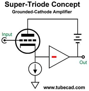
Super-Triode Basics
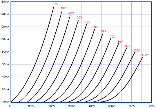
The aim is to superimpose the triode's sonic footprint on the beefier device's output signal. Imagine a single 300B that could put out 200W, which will give you a good idea of what an ideal super-triode amplifier might be like. Running the triode under constant-current is critical, as this mode of operation ensures the least distortion from the triode. For example, look at the following set of triode plate curves and imagine a vertical line at 300V. Then read the amount of current change per 10V of grid voltage change. As we go from -70V to -60V, we get about 10mA of change in conduction. As we go from -60V to -50V, we get about 12mA; from -30V to -20V, 20mA of current increase. In other words, not very linear.
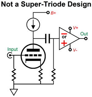
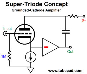
Now, imagine a horizontal line, instead, at 60mA. Each 10V grid voltage increment results in the same plate-voltage increment. This is the sort of linearity that we seek. If the triode delivers any power into the external load impedance, then a diagonal load line will be imposed upon the plate curve, resulting in some distortion. Thus, the beefy output device must do all the hard work of driving the external load impedance. Finally, the triode must "know" what the beefy output device is doing. In short, a negative feedback loop must be imposed that lets the triode correct the beefy output device's output signal. When all three conditions are met, we get a super-triode amplifier. Here is a negative example, as the following design is not a super-triode.
This design does meet two conditions, the triode's constant-current operation and not delivering any power to the external load, but one key feature is missing: the output must be fed back to the triode so that the triode can control the output. In the above circuit, the triode has no idea what the beefy output device has done to the triode's plate signal.
The triode receives the input signal, with its cathode following the signal. As the cathode moves off its idle voltage, however, the beefy power amplifier both amplifies and inverts the cathode signal, which then gets relayed to the triode's plate via the floating power supply, creating an active negative feedback loop, with the triode in charge of the output. This is the raw concept. Actually making it work will look more like the following.
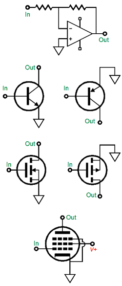
The floating power supply gets replaced by a large-valued capacitor. The plate resistor gets driven not by the triode, but by the beefy inverting power amplifier stage. This inverting stage can take many forms, such as these.
Any of these or any combination of them could be used in making a super-triode amplifier, as each invert its input signal. Here is an example from Post 372, where we see a NPN transistor used in a common-emitter-amplifier arrangement.
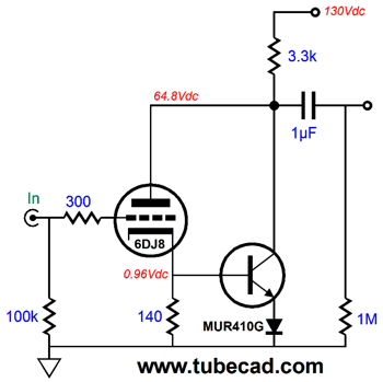
Using a pentode lends an all-tube flavor, which would please many, while still delivering far more power than the triode could by itself.
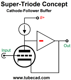
The triode draws a near constant 40mA, while the pentode undergoes the near 100mA current swings. This means, by the way, that the output transformer primary can only see a maximum current swing of 100mA, not its 160mA idle current. If more output power is required, then a beefier pentode can be used or several pentodes could be run in parallel. Before we stray too far away from the basic concept of the super-triode arrangement, let's look at the cathode-follower version.
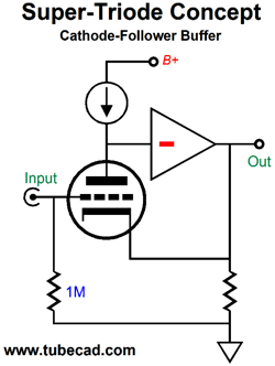
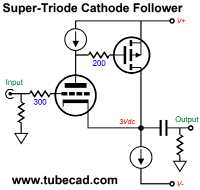
No signal gain this time; instead, the cathode follows the grid signal. If the cathode fails to trace the signal, the triode's plate voltage will alter, causing the beefy inverting gain stage to force the needed correction on the cathode's voltage. This is the basic idea, which the following illustration only slightly fleshes out.
Using a P-channel MOSFET as the beefy inverting gain stage, we get the following design.
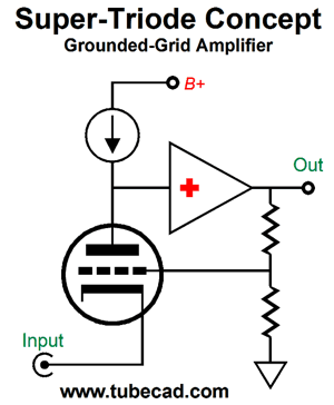
Making a super-triode grounded-grid amplifier requires using a beefy non-inverting gain stage, as we return the output to the grid, not the plate or cathode.
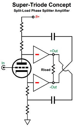
This arrangement allows much freedom in selecting a desired signal gain, as we can go from unity-gain to a gain greater than the the triode's amplification factor. That was a quick summery of the three basic triode topologies. We have left out the rare, almost unknown, grid-amplifier (AKA inverted amplifier), which uses the plate as if it were a grid and takes the output at the grid, which draw current purposely. Another basic topology that we shouldn't forget is the split-load phase splitter. Applying the super-triode treatment is interesting, as two beefy inverting gain stages are needed.
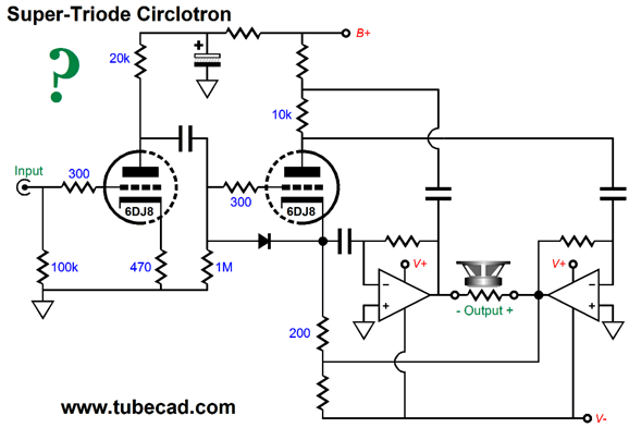
The two large-valued capacitors ensure that the triode operates under near constant-current condition. The gain approaches 2 (+6dB), differentially. This could be the basis for a mind-twisting circlotron power amplifier. Imagine two beefy solid-state power amplifiers and a single DHT triode, such as the 2A3 or 300B. Alternatively, we could use single 6DJ8, whose first triode would provide the required signal gain, while the second triode would deliver the super-triode control over the circlotron output.
The above is what I drew late last night. At the time, it made perfect sense. It just might, but I have to run some SPICE simulations on the topology first, which is why I adorned the schematic with a question mark.
DHT Super-Triode Sans CCS
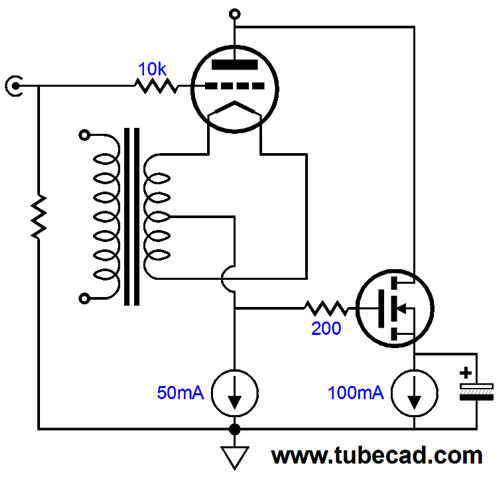
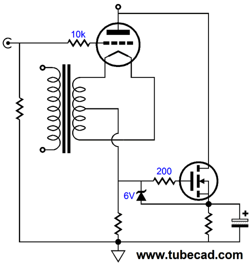
The answer is yes. Here is a constant-current-source-free super-triode output stage.
No constant-current sources here. The two cathode resistor in series set the directly-heated triode idle current. The top cathode resistor is capacitor bypassed, so no AC voltage division occurs, so the bottom cathode resistor sees any movement in cathode voltage without any attenuation. To be honest, such a setup makes me nervous as hell, which is why I added the 6V zener, as I feared the MOSFET going up in smoke. An additional problem is that the bottom cathode resistor will not all that large in value. For example, if the DHT output tube draws 50mA, then cathode resistor between 82 to 120 ohms will be used. One workaround would be to give the MOSFET its own source resistor, which helps set the for the MOSFET. More importantly, it allows us to use single, larger-valued cathode resistor.
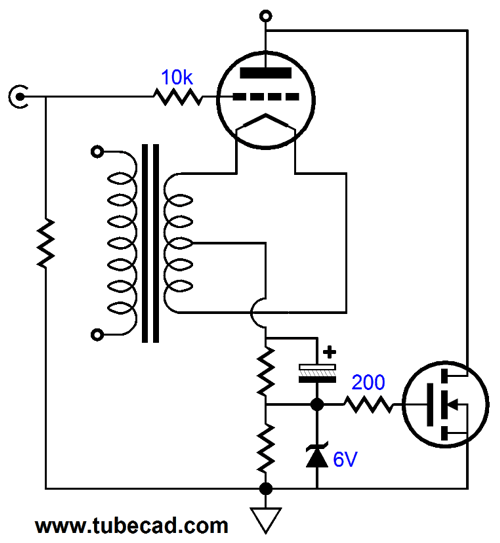
An additional problem is that the bottom cathode resistor will not all that large in value. For example, if the DHT output tube draws 50mA, then a cathode resistor between 82 to 120 ohms will be used. A 120-ohm resistance falls far short of being a constant-current source. One workaround might be to borrow a technique from the cascode topology. Cascoding allows us to sidestep Miller-effect capacitance and move beyond the triode's seeming gain limit of its amplification factor (mu).
The cascode's input grid is shielded from the big output signal voltage swings by the top triode's cathode, which means that the grid-to-plate capacitance does not get amplified by the signal gain (i.e. Miller effect). The bottom triode also benefits from not having a large plate resistor would would necessarily subtract from it transconductance, which allows for the cascodes greater potential gain. Sometimes, we desire even more gain. In these cases, the following variation allows us to use a much-larger-in-value plate resistor, which results in much higher gain. (See post 303 for more details.)
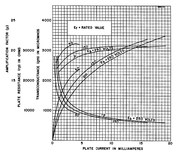
Without the added constant-current source, the plate resistor would have to be 10k. Why not just use a 20k plate resistor and lower the idle current to allow the same voltage relationships to obtain? Increased noise and less transconductance due to lower idle current flow. In the following graph, we see the 6SN7 key attributes plotted, mu (µ), rp, and gm.
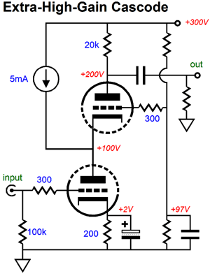
Note that transconductance increase with plate current draw. With the added constant-current source, the bottom triode runs hot, but the top triode runs half as hot. Since the bottom triode is doing the real work, this division works well. Applying this technique to the super-triode single-ended output stage requires using a PNP transistor and an extra cathode resistor.
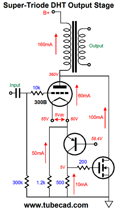
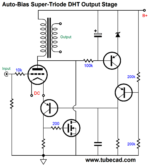
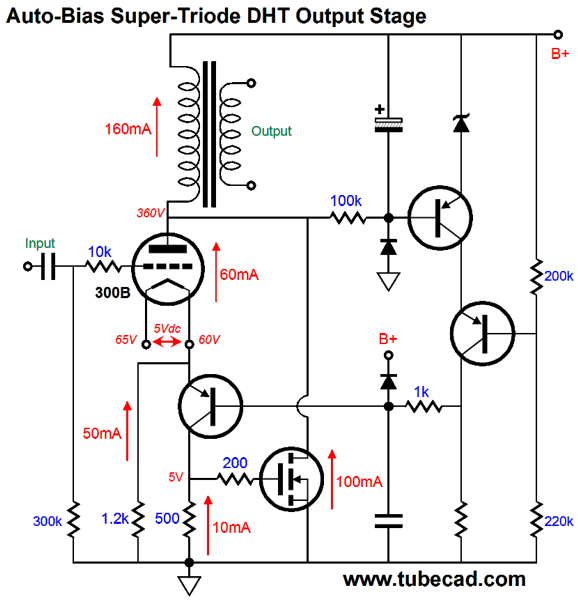
The DHT output tube draws 60mA, while the 1,200-ohm cathode resistor draws 50mA, leaving the last 10mA to flow through the 500-ohm collector/cathode resistor to draw 10mA. Since 500 ohms is five times greater than 100 ohms, the value we would have used otherwise, we get five times more signal gain. The huge problem is getting the MOSFET to draw the right amount current and not to melt. Remember that unlike the triode, the MOSFET offers screaming transconductance, at least 10A per gate volt. In contrast, the 300B offers 5mA per grid volt change; in other words, 2000 times less. One workaround is to use an auto-bias scheme to control both the triode and MOSFET's current conduction. Let's start with the auto-bias version from post 372, which uses the output transformer's primary DCR as a current-sense resistance.
The top PNP transistor uses the zener as its voltage reference, which it then compares to the voltage drop across the output transformer's primary DCR. If the drop is too low, the transistor lessons its current flow, which causes the triode's cathode voltage to fall, which prompts the triode to conduct more current. If the drop is too high, the transistor increases its current conduction, which causes the triode's cathode voltage to rise, which prompts the triode to conduct less current. We need only to add a cathode resistor to the above circuit and fiddle with the resistor value to arrive at the following circuit.
If we are really brave, we can replace the 500-ohm collector resistor with a 10mA constant-current source. One observation I must make is that the super-triode treatment is not restricted to transformer-coupled single-ended amplifiers. Indeed, such an amplifier may not prove the best use of the super-triode treatment, as the output transformer is only burdened by the triode's dead current flow. In other words, since the triode's conduction remains steady, its current flow does not drive the speaker, but it does stress the transformer's core. In contrast, in a transformer-coupled, push-pull output stage, the two triodes constant current draw results in a net tie, so no excessive core magnetizing obtains. Moreover, if we restrict the triode's plate swings to the same level of voltage swing seen by the loudspeaker, the distortion will prove far lower.
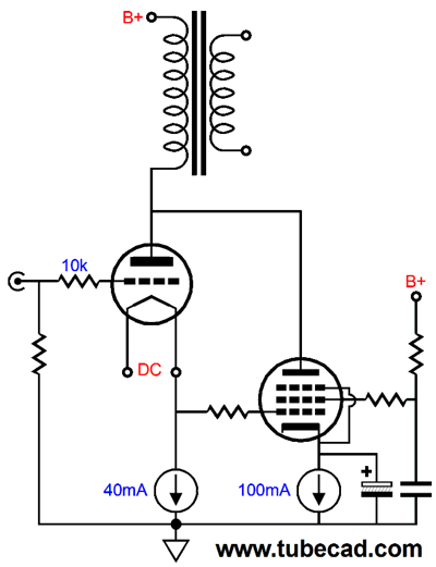
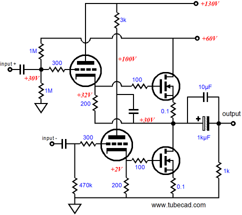
Super-Triode OTL Amplifiers Several readers have asked if the super-triode approach is limited to single-ended output stages or if push-pull, OTL, super-triode output stages were possible. My answer has been to check out post 178 and post 179. There, you will see circuits, such as the following, a super-triode totem-pole OTL output stage
The assumption when I drew that schematic was that lateral MOSFET, such as the BUZ901, would be used. Now, I would use an IRF HEXFRED instead, as they would allow larger cathode resistor values or constant-current sources to be used. The IRF-type MOSFET would also allows us to use a beefier triode, say the 6H30 or 5687 or ECC99. For eXample, the 6H30 with a cathode-to-plate voltage of only 90V and cathode-to-grid voltage of 5V will draw 10mA.
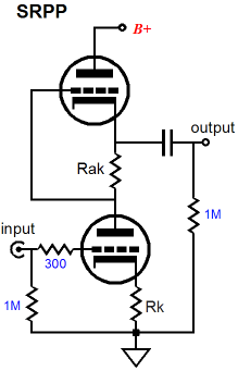
Today, I would lose the 0.1-ohm source resistors, as we want to preserve as much of the MOSFET's transconductance as possible. One huge problem is setting the MOSFET's idle current. My preference would be for some form of active auto-bias on just one MOSFET, and then using a DC servo on the other MOSFET. Other push-pull super-triode topologies are possible, such as the SRPP.
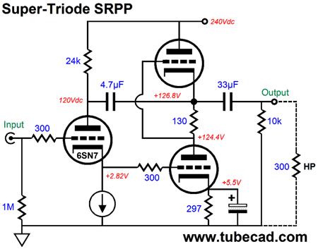
The SRPP is marvel, as it is push-pull amplifier that accepts an unbalanced signal and creates its own internal phase splitting function. The catch is that the SRPP must be optimized for the intended load impedance. Adding a super-triode overlay is simple enough. First, we use a triode as the input tube and as the electronic yardstick. Second, we terminate the input triode's cathode with a constant-current source. Third, we use a large-valued capacitor to bridge the SRPP's output to the input triode's plate. We're done.
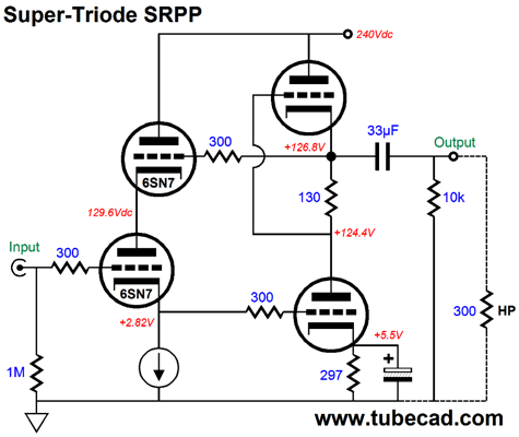
No doubt, many are thinking to themselves that the input 6SN7 is actually doing more than just drive the SRPP, as it looks like it is actually powering the external load, if only partially. Well, then, how how about the following version, does the input triode drive the external load?
What about driving low-impedance headphones, not 300-ohm cans? It could be done many parallel output triodes (six times for for a 50-ohm load) or with a step-down transformer that reflects the 32- or 50-ohm load as 300 ohms to the SRPP stage.
Next Time
//JRB
I believe that when Mr. Telfer writes "electronic crossovers" he actually means passive crossovers, which contain no electronic devices, such as diode and tubes and transistors, but do contain inductors, capacitors, and resistors.
Patreon
User Guides for GlassWare Software
For those of you who still have old computers running Windows XP (32-bit) or any other Windows 32-bit OS, I have setup the download availability of my old old standards: Tube CAD, SE Amp CAD, and Audio Gadgets. The downloads are at the GlassWare-Yahoo store and the price is only $9.95 for each program. http://glass-ware.stores.yahoo.net/adsoffromgla.html So many have asked that I had to do it. WARNING: THESE THREE PROGRAMS WILL NOT RUN UNDER VISTA 64-Bit or WINDOWS 7 & 8 or any other 64-bit OS. I do plan on remaking all of these programs into 64-bit versions, but it will be a huge ordeal, as programming requires vast chunks of noise-free time, something very rare with children running about. Ideally, I would love to come out with versions that run on iPads and Android-OS tablets. //JRB |
Kit User Guide PDFs
E-mail from GlassWare Customers
High-quality, double-sided, extra thick, 2-oz traces, plated-through holes, dual sets of resistor pads and pads for two coupling capacitors. Stereo and mono, octal and 9-pin printed circuit boards available.
http://glass-ware.stores.yahoo.net/ Support the Tube CAD Journal & get an extremely powerful push-pull tube-amplifier simulator for TCJ Push-Pull Calculator
TCJ PPC Version 2 Improvements Rebuilt simulation engine *User definable
Download or CD ROM For more information, please visit our Web site : To purchase, please visit our Yahoo Store: |
|||||||||||||||||||

.jpg)


| www.tubecad.com Copyright © 1999-2017 GlassWare All Rights Reserved |