| John Broskie's Guide to Tube Circuit Analysis & Design |
21 December 2008
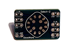
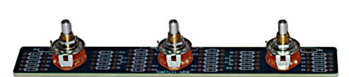
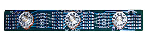
New Signal and Capacitor Selector Switches
The capacitor selector makes wiring up an Aikido board an easy task, as the two coupling capacitor outputs from each channel attach to the small PCB and the two outputs leaving the switch allow choosing between coupling capacitors C1 or C2 or both C1 and C2 in parallel. Not a big deal, but then many small little benefits do add up to something desirable; at $6 USD each (now on sale for $5.10), they become even more desirable.
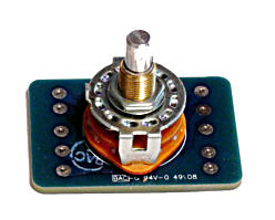
Resurrection of the TCJ 36-Position Stepped Attenuator First, I ran out of the switches, which were only slowly being restocked by the distributer (months between shipments). Second, the attenuator could make loud popping noises during switching. The clicking noise depended on the electronics used, as I found some tubes were quite susceptible to the switching-induced pops, while other tubes were largely indifferent. The switches I used were non-shorting, which meant that the output resistance to ground would sharply jump as the switch moved from contact to contact. The obvious workaround would be to use shorting switches or a coupling capacitor on the attenuator’s output; the first solution was not possible as the switch manufacturer did not make a shorting PCB-mount switch; the second solution would be inelegant. Thus, I turned to Elma switches, which are supremely fine, but hugely expensive and I had to purchase a mammoth order to get a reasonable price on the switches, which made me nervous. (I will order more Elma switches in the future, when I am up to writing a big check, as the Elma heavy-gold contact switches are ideal for audio use.) So what has changed? I tried a few experiments and I found that I could mount the non-PCB-mount rotary switch on a PCB (the one with solder eyelets and shorting contacts), if I made the holes snuggly tight. Interestingly enough, only I can insert the switches into the PCB, as no one else has been able to do so. It’s sort of like King Arthur in reverse, which is less a testament to my bear-like strength and eye-surgeon dexterity as it is to my relentless determination and my strong belief in its possibility. All attenuator kits will ship with the switches inserted into the PCB, so no worries.
The kit will also ship without resistors, but resistor packs will be available in
either
metal-film or carbon-film resistors and in several resistance values. The PCB is 1.4 by 9 inches and the switch spacing is 3 inches.
A Few Comments on Power Booster Amplifiers Speaking of potential voltage swings, I do not understand why the Musical Fidelity 550K power-booster does not come with an input sensitivity control, so that one’s 2.5W flea-power amplifier can access the full 500W of output, not just 25W. Or if the gain cannot be selected, because the power-booster amplifier does indeed require a power amplifier to drive to full output, then make the rail voltages and idle current selectable, as a 500W push-pull class-AB amplifier would make a nice 25W push-pull class-A power amplifier. Watts, like wealth, is relative. The owner of a 2.5W amplifier would be just as thrilled to have 25W as the fellow with the 50W would be to have 500W. So are 500W needed, if we started with 2.5W to 10W? My guess is that most of us using tube-based single-ended amplifiers would love to have 25W to 50W to push our woofers about, particularly if those 25 to 50 watts came from a single-ended amplifier, albeit a solid-state amplifier. This leads to the Nelson Pass’s Zen amplifier.
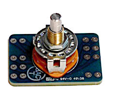
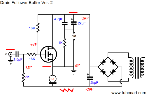
The Zen amplifier uses a single power MOSFET as the amplifying device. It also uses a low-resistance input resistor as part of its feedback loop to compensate for the MOSFET’s high input capacitance. I believe the standard value for this input resistor is 2k, although I am sure I have seen some use as little as 500 ohms. Well, 500 ohms is no big deal for any power amplifier, but is a tough load for most line-stage amplifiers. (We all know that a beefy Aikido could easily be built up that would easily drive 500 ohms, as many are driving 300-ohm headphones with beefy Aikido line amplifiers, including myself.) Now imagine that we place several power MOSFETs in parallel, so that our Zen knockoff can put out 25 to 50 watts. Such an amplifier would require a very low-valued input resistor due to the paralleled input capacitance. But even a 200-ohm input resistance would not be a big deal to a power amplifier, no matter how flea powered. By the way, do not imagine that we are tied to only the Zen topology, as the following circuit would make a worthy candidate for power enhancement via more parallel output devices.
(If your imagination is up to it, imagine the constant-current source at the MOSFET’s source is replaced by an inductor, which would halve the wasted heat and needed power supply voltage. Remember, a perfect inductor displace no voltage. By the way, note how the power supply is floating, which means that a separate power supply is needed for each channel.) Before I sign off, I must mention that a few TCJers were thrilled by the prospect of building the push-pull, cathode follower, power-booster amplifier from last time. The big difficulty would be finding the right transformers. The input transformer needs to be a low-power, high-winding ratio output transformer and the output transformer needs to be a brute, with a fairly low winding ratio−alas, both are hard to find. The best workaround might be to use the trick used in old Quad electrostatic loudspeakers: use two input transformers, one for each output phase, which effectively doubles the winding ratio of either transformer. This same trick could be used with the output transformer: the input transformers would parallel the transformer’s primaries and series their secondaries and the output transformer would also see their primaries paralleled and their secondaries in series. Next Time //JRB
|
Kit User Guide PDFs
And
High-quality, double-sided, extra thick, 2-oz traces, plated-through holes, dual sets of resistor pads and pads for two coupling capacitors. Stereo and mono, octal and 9-pin printed circuit boards available.
Designed by John Broskie & Made in USA Aikido PCBs for as little as $24 http://glass-ware.stores.yahoo.net/
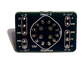
The Tube CAD Journal's first companion program, TCJ Filter Design lets you design a filter or crossover (passive, OpAmp or tube) without having to check out thick textbooks from the library and without having to breakout the scientific calculator. This program's goal is to provide a quick and easy display not only of the frequency response, but also of the resistor and capacitor values for a passive and active filters and crossovers. TCJ Filter Design is easy to use, but not lightweight, holding over 60 different filter topologies and up to four filter alignments: While the program’s main concern is active filters, solid-state and tube, it also does passive filters. In fact, it can be used to calculate passive crossovers for use with speakers by entering 8 ohms as the terminating resistance. Click on the image below to see the full screen capture.
Tube crossovers are a major part of this program; both buffered and un-buffered tube based filters along with mono-polar and bipolar power supply topologies are covered. Available on a CD-ROM and a downloadable version (4 Megabytes). Download or CD ROM
|
|||


| www.tubecad.com Copyright © 1999-2008 GlassWare All Rights Reserved |