| John Broskie's Guide to Tube Circuit Analysis & Design |
Simple Push-Pull Amplifiers 21 March 2003 Simplest Push-pull Tube Amplifiers
The simplest push-pull amplifier is one that only requires two active devices. The amplifier at the right uses an input transformer to split the phase and provide signal gain. The output transformer provides impedance matching between the output tubes and the loudspeaker. With only five parts, this amplifier is as simple as it gets. Yet a great deal of complexity is hidden: the transformers are anything but simple, as no transformer lives up to its ideal. The wire used has resistance; the core, hysteresis; and the two windings, capacitance. Let’s add some leakage inductance to really spoil the party. In other words, we are going to have to pay, either for a quality transformer or in performance. Since we are not likely to get rid of the output transformer in a tube amplifier, we should focus our attention on eliminating the input transformer. The two amplifiers shown below do just that. The leftmost amplifier uses a center-tapped choke to split the signal’s phase. In other words, it takes the input signal and creates a complementary inverted signal to drive the second triode. The rightmost amplifier relies on a balance input signal to drive both output tubes. In both amplifiers, the input transformer’s signal gain has been shifted back to the line amplifier, as the line amplifier must now provide sufficient gain to drive the output tube to full output. Depending on the output tubes, this increased demand for gain can easily be excessive (150Vpp), thus a high-transconductance output tube such as the 2A3, EL34, EL84, or 8417 should be used. (Actually, even the input transformer version also makes great demands on the line amplifier, as the output tubes’ input capacitance is effectively increased by winding ratio squared, which means that while the output voltage swing is small, the line stage’s output current at high frequencies is greatly increased over a conventional amplifier.)
Now, let’s look at some bad ideas. A trick used in cheap amplifiers was to forgo the expense of an input transformer or phase splitter circuit that used an extra triode, which makes a circuit more than casually similar to the SRPP. In the amplifier at the right we see the top EL34 being driven by the input signal, but the bottom EL34 receives its drive signal from the signal developed at the top pentode’s screen. What’s wrong with this amplifier? The degree of balance between tubes varies with the load impedance and both the first pentode’s distortion and bandwidth limitations are just cascaded into the bottom pentode. Furthermore, power supply noise does not cancel, as it would normally. Still, while the results were not perfect, they were good enough for many applications, such as cheap phonographs.
The last amplifier design also carried the limitation of requiring the use of pentodes. On the other hand, the amplifier below can use either triodes or pentodes, as the bottom tube’s drive signal comes from a tap in the primary winding. This circuit is an even closer equivalent to the SRPP than the previous circuit. But it too shares the same shortcomings. (In a perfect world that held perfect tubes, transformers, loads, and power supplies, these circuits would work much better. Sadly, that’s not the world we live in.) The only advantage to these two circuits is that they force a class-A operation on the amplifiers. 
As a tube push-pull amplifier must see a balanced drive signal to work well, it looks like using the input transformer or a balanced line signal are our best bets. Or are they? The next amplifier requires a floating power supply, as it shifts its reference point from ground to the middle of the two 47k input resistors. This shift in reference creates a phase splitter out of the two resistors, allowing a single-ended (unbalanced) line amplifier to be used. This phase splitter is about as pure as it gets, as resistors do not limit frequency response or add the phase shifts of the inductively based phase splitters. But the demand made on the line in terms of needed voltage swing and gain will be great. In addition, any parasitic capacitance between the floating power supply and the grounded chassis can upset the high-frequency phase splitting (insulating washers might counteract this).
Simplest MOSFET Amplifiers We all know that while tubes have no problem swinging large voltages, they have a hard time delivering high current. So, let the tube do what it does well and let MOSFET do what it does well. 
The amplifier shown above is simplicity itself. A balanced tube-based line stage delivers all the voltage swing (+/- 20 volts) that the MOSFETs need to be fully driven into an 8-ohm load. The center-tapped choke creates a virtual negative power supply rail. Consequently, the load can see voltage differentials of 20 to 24 volts in this circuit (25W to 30W). (If twice the idle heat is acceptable, then the choke can be replaced with two constant-current sources. See below for illustration.) This amplifier offers low distortion and low output impedance. The downside to this amplifier lies in the output stage having to be biased in pure class-A for this topology to work with most chokes.  Zeus-Style Power Amplifier The all-MOSFET amplifier above has actually been beautifully crafted by a gifted English electrical engineer, Susan Parker. She named her amplifier the Zeus Power Amplifier. (The parts and voltage values shown are only for illustration and do not represent what the actual Zeus amplifier holds.) Be sure to check her site out for a more detailed explanation of her amplifier. Yes, there are women audio circuit designers (EveAnna Manley, the "Tube Chick" comes readily to mind).  Simple resistor-based bias arrangement Adding three resistors eliminates the need for a bias power supply. In the amplifier above we see the three resistors in place. Note that the input transformer’s secondary is being loaded by the two 280k resistors in series. This is actually a benefit, not a detriment. Each transformer has its optimal load impedance, which is easily found with a square-wave generator, a potentiometer and a scope. As 560k is unlikely to be the right value for every (or any) input transformer, an extra loading resistor can be placed directly across the secondary. Also note that the single 10k resistor allows the idle current to be set by varying its value and that this resistor could easily be replaced with potentiometer or, better still, a potentiometer and a resistor wired in series.  Push-pull MOSFET amplifier with source feedback A different tack is shown above. Effectively, we have placed a feedback loop across the output transformer. Although the feedback may introduce a few stability problems, this circuit is worth experimenting on. Imagine placing a battery across the output connections. One MOSFET will have its source forced positive, which will serve to turn it off. The other MOSFET will have its source forced negative, which will serve to turn it further on. The net result is that the output stage will buck the imposed voltage.  Push-pull MOSFET amplifier with voltage gain and feedback Another approach would be to use some of the MOSFETs high transconductance to provide voltage gain. Configuring the MOSFETs as grounded-source amplifiers unloads the input transformer the task of providing signal gain. The MOSFETs present a high output impedance at their drains, so a feedback loop will be needed. The amplifier below uses two feedback loops to lower the output impedance and distortion. Furthermore, they allow us to easily set the needed bias voltage. Note that in this case, the input transformer’s secondary is loaded by the two 20k resistors in series, not by two 300k resistor strings in series. (The MOSFETs are configured to invert the signal at their gates, so the connection between resistors is effectively grounded.) Another tack might to go after the output transformer, as shown below. Once again we are back to using the MOSFETs in a source-follower configuration. This time, though, the output transformer has been replaced by a center-tapped choke. Because the current flowing through the two paths away from the center tap are equal at idle, the choke does not become magnetized, as it usually does when it experiences unidirectional current flow. Consequently, the choke’s core does not need to be air-gapped, although it can be.  Push-pull MOSFET class-A buffer/amplifier All wire has some DCR, which against a high idle current will cause a DC offset voltage at the extremes of the choke’s winding. However, as the amplifier's output is not referenced to ground, the speaker will never see a net DC voltage differential. This amplifier, unlike the previous MOSFET amplifiers, must be run in strict class-A, so the idle current will be quite high, at half of the peak current demand. How do we find the peak current demand? This amplifier is effectively the equivalent to a normal source follower amplifier with +/- voltage rails equal that of this amplifier’s single rail; the magic of inductors. In this case, we can assume that 12 volts of the power supply’s 15 volts will be deliverable into each side of an 8-ohm load, so a total of 24 volts (peak voltage) would require 3A of peak current (as one terminal goes up the other goes down). Thus, a total idle current of 6A is needed (24V / 8 ohms ), 3A per MOSFET. In other words, the 8-ohm load can be seen as being the equivalent to two 4-ohm loads in series, whose common connection is grounded; thus, 12V/4 ohms = 3A. (If a floating power supply were used, one not ground referenced, the amplifier's negative output could be grounded and its positive output would still be at ground potential, as the center tap would be at some negative voltage—just a note for the advanced practitioner.) Alternatively, we could eliminate the output transformer (or choke) altogether. In the amplifier below, we see dual floating power supplies and two feedback loops in parallel. This circuit is the classic Circlotron remade. It may look odd, but it functions identically to a conventional bipolar power supply source follower amplifier, as shown further below. The only difference is that only N-channel MOSFETs are used and two power supplies are needed. The first difference is more important than the second. Part of the simplicity of this amplifier lies in its use of identical output devices, as P-channel MOSFETs never exactly match their N-channel complements. Consequently, using the device for both output decrease greatly improves the natural balance of the amplifier. Unfortunately, we must use an input transformer to create the required balanced drive signal.  Simple Class-AB Circlotron Amplifier Simple Class-AB Circlotron Amplifier
Using P- and N-channel MOSFETs allows us to get away with a single-ended input signal. In the amplifier below we see complementary output devices configured as source followers. As this amplifier offers no voltage gain, the line amplifier will have to swing the full +/-30 volts needed to bring the amplifier to full power. Because it offers no gain, this amplifier uses all its output stage’s transconductance to provide a low output impedance and a low distortion.  MOSFET push-pull buffer/amplifier MOSFET push-pull buffer/amplifier
The two coupling capacitors are a nuisance, although much less so than an input transformer. Still, it would be nice to do away with them. One possibility is to use two single cell batteries, As for example. One advantage to using batteries is that as they discharge, the idle current will decrease, not increase, as often happens in other battery bias schemes. Alternatively, we can just use resistors, as shown below.
Shifting the ground and output creates an amplifier out of the buffer topology. The amplifier below inverts the input signal at the output and uses two feedback loops to set the gain and lower the output impedance and distortion. Won’t the signal delivered to the load be compromised because of the electrolytic capacitors? Yes, it will. But guess what: the signal is compromised because of the electrolytic capacitors in a non-floating, conventional amplifier as well, as the output currents flow through power supply capacitors in both amplifiers equally. It’s just that we seldom think about the power supply’s parts as being in the circuit, although they are.
A note for the advanced practitioner, if the power supply’s capacitors didn’t find a connection to the power transformer’s center tap, then the output from this amplifier would be entirely capacitor coupled, which would eliminate the DC offset worries (a 1k resistor should then be connected from ground to the capacitors’ common connection, in case the capacitors differ in value). For me, though, the bigger problem is the mismatch between output devices. The next variation on the theme answers that problem.
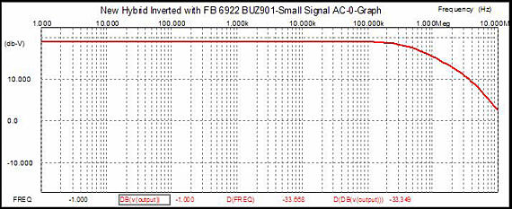
As the graph below shows, the performance is excellent for so simple an amplifier. Translated into a THD percentage, the distortion comes in at about 0.1% at 1 watt output and 3% at full output, 35 watts. The output impedance is about 1 ohm. Bandwidth extends from DC to 200kHz. The 170pF capacitor is a cheat of sorts to extend high-frequency, as the 12k resistors working into the MOSFET’s input capacitance limit the frequency response. The gain is only 2.4 times the input, so the line amplifier will have to be capable of putting out 10V peak. More gain would equal a higher output impedance and more distortion and a choice between a lower input impedance or a less extended bandwidth, which might not be a bad idea, as I have heard some excellent sounding amplifiers with high output impedances and 60kHz bandwidths.
Simple MOSFET SRPP 
The output must be capacitor coupled because of the uni-polar power supply, but with sufficient bypassing, the capacitors should not harm the sound and will actually offer a nice safety margin. Once again we are back to a low input impedance, so it is worth looking into the trick of using a negative power supply rail to allow a larger set of input and feedback resistors.
Simple Hybrid Push-Pull Amplifiers 
Alternatively, this technique could be applied to a wimpier power amplifier for headphone use. In fact, a 6GM8, a ±12V DC-DC voltage converter, and a dual power amplifier IC could be held in an Altoid tin, while an external battery pack could hold a lead-acid 6V battery or four D cells for those times when a wall wart isn’t available. The 6GM8 is a twin triode that looks like 6DJ8 on the outside and the inside, as it too is a frame-grid triode. It differs from the 6DJ8 in that is has a specially treated cathode that can emit a strong electron stream under only 10 volts. Of course, many would as soon rather drink red wine with fish than use an IC in their audio equipment, even if that IC were as slick as an LM12. So something more difficult (I mean “discrete”) is needed. The amplifier below uses tubes, transistor, and MOSFETs. The triode works into a current mirror that reproduces the current fluctuations in the triode in the PNP’s collector, which is loaded by the 5k resistor. The signal that was inverted at the triode’s plate is then inverted again by the transistor. The gain is much higher than you might expect, as the triode is not loaded by the 5k resistor, but by the 200-ohm resistor. This means that the triode loses little of its transconductance and undergoes fairly large current swings. The transistor in turn relays the current into the 5k resistor, much as a cascode circuit would. In other words, because the 5k resistor is not in series with the triode, the triode’s transconductance is not reduced; more transconductance means more gain. This amplifier uses no internal coupling capacitors, but it does require an output capacitor. It looks like the 5k resistor serves as a feedback resistor, but the amplifier’s gain is far less than the gain the 100-ohm and 5k resistors would imply. If the transistor were loaded by a constant current source, then the 5k resistor could attach to the output and work nicely as a feedback resistor. The diodes are used as voltage drops and the string could be replaced by a voltage reference or, gasp, a zener. One problem with circuit is that its PSRR isn’t all that good. Using a pentode or a cascode in place of the triode would help, but there is a better way. 
The next circuit retains the current mirror and uses a bipolar power supply for the output stage. (Note the lower rail voltages.) The bottom triode effectively equals a 10k resistor, which allows a good deal of gain to be created. The bottom triode also allows a path to the negative power supply’s noise, which will then counter the positive power supply’s noise and cancel at the 250-ohm resistor. Nice trick. All in all, not a bad design. 
Here are some possible embellishments.
Feedback can be easily added from the top triode’s cathode
to the output. A DC servo could be added to keep the output centered
at 0 volts. A lower mu triode, such as the 5687 might be fun to listen
to. And finally, the PNP transistor could be replaced by a P-channel
MOSFET.
Now the two triodes in series also define a 50% voltage divider, so at their midpoint, the power supply’s noise will be halved as well. Cascading the input circuit into the output stage results in the top and bottom MOSFET seeing the same amount of power supply noise, which means that the power supply noise cancels at the output — another nice trick. The 6GM8 is used to good advantage here and the two 1M resistors are there to protect the output stage when the tube is warming up or absent. The next amplifier displays the same fundamental topology, but instead uses a high-voltage power supply, coupling capacitor and 6DJ8s. Note the 100µF capacitor that connects the top triode’s plate to the 40-volt power supply. If this capacitor went to ground, the PSRR would be much worse. Think Aikido, not Zen. Note: both circuits require that the output stage be run in strict class-A operation, as the White cathode follower output stage can only work if the top MOSFET is always conducting; in this case, about 1A at idle. 
The next circuit is a buffer/amplifier that provides no voltage gain. The tube’s job is to provide current to drive the MOSFET’s heavy input capacitance and to provide a high input impedance. The output stage can be run in a lean class-AB or a rich class-A. A DC servo loop would be a good addition and the ±90 power supply could be parasitically derived from the ±30 power supply. 
What would happen if the output were shorted to ground? The tube would still follow the input signal and the output stage would undergo huge current swings. If the power supply were left floating, the swings would drive the power supply’s center tap up and down in anti-phase to the input signal. The amplifier shown below makes this topology clear. The buffer has become an amplifier with much gain and a high output impedance, making it a perfect candidate for feedback. But where do we apply the feedback loop?
Since the output is inverted relative to the triode’s grid, a feedback resistor can bridge grid to output. Now the ratio between the input resistor and the feedback sets the amplifier’s gain. The problem is that thefeedback resistor is of so high a value that any stray capacitance will bring the high frequency response down. Lower-valued resistors could be used, but then the input resistor would load down the line stage’s output.
The sneaky technique would be to apply the feedback to the top triode’s plate and the bottom triode’s cathode. The next amplifier schematic makes this clear. Here the power supplies act as direct shorts for the output signal. For example, imagine that a +1V pulse were forced on the amplifier’s output. The top triode would see a greater cathode-to-plate voltage and would conduct more current, which would pull its cathode up by 1/mu. Conversely, the bottom triode would see a lesser cathode-to-plate voltage and would conduct less current, which would pull its plate up by 1/mu. Now, the top MOSFET would increase its conduction while the bottom MOSFET would decrease its conduction. Because the top MOSFET is conducting more, its drain would pull down its connection to its power supply and the output would swing down: feedback, in other words. 
The triodes act as feedback resistors and they set the gain of the amplifier. So, is the gain of this amplifier 33, the mu of the 6DJ8? No, it is closer to 10 because the resistors in the input stage are not bypassed. Should these resistors be bypassed? No, as it increases the amount of distortion beyond the increase in gain. In fact, the triodes nicely complement the MOSFETs and the distortion is reduced beyond what we would expect from feedback alone. Below is a B² Spice A/D schematic and simulation of this topology. 
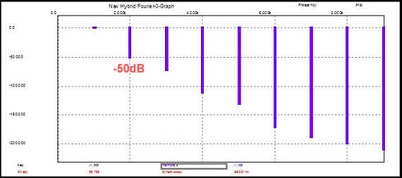
The circuit differs slightly from the one above it, as I was exploring different ways to reduce distortion. Thus, I added resistors in series with the power supplies to simulate the power supply’s DCR and 0.45 resistor at the top MOSFET source. This resistor reduces the N-channel MOSFET’s transconductance so that it might better match the P-channel MOSFET’s naturally lower transconductance. (I’ll admit it: it is so much easier to tweak an amplifier in SPICE than it is on an actual workbench. Of course, once you are happy with the results in SPICE, go the workbench to confirm.) First of all, note the wide bandwidth: flat from DC to 100k. Second, note the beautifully decreasing harmonics. (One advantage to this feedback arrangement is that few people would recognize it as such, which means that it could be touted as being “feedback free” in high-end-audio magazines if one were so inclined.)
All-Tube OTL
//JRB
|
TCJ Push-Pull Calculator TCJ PPC Version 2 Improvements Rebuilt simulation engine
Download or CD ROM For more information, please
visit our Web site : |
|||


| www.tubecad.com Copyright © 1999-2004 GlassWare All Rights Reserved |