| John Broskie's Guide to Tube Circuit Analysis & Design |
| Post 244 22 September 2012
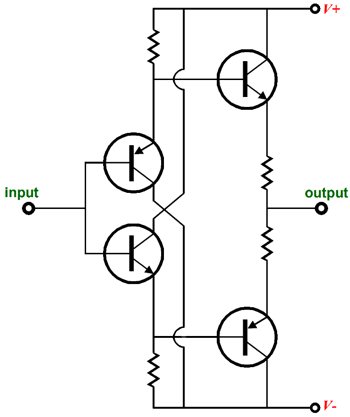
Mighty Diamonds
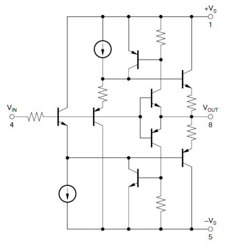
Some harsh critics would add that it does not deliver much either. I have covered the circuit and its modification here before, for example in Blog 232 and Blog 187. But for over a year, I have been meaning to write about a significant modification to the basic circuit that I came up with. In fact, I planned on including it in my last post. Here is the big problem with the naked diamond buffer circuit: it works great as long as you do not ask to work hard, which is a tad bit sad, as that's exactly what we want from a buffer. The makers of OpAmps know about this problem and they have come up with some clever workarounds, such as this circuit found in the OPA633.
As long as the input stage can handle driving the output transistors, the two transistors nested inside do nothing; in fact, they are not even turned on. But once the input stage falters, they begin conducting and take over the task of driving the output transistors. Clever, very clever. The LMH6321 tackles the same problem in a different way: it builds a very robust, dual, push-pull, input stage that can easily drive the output transistors to full output.
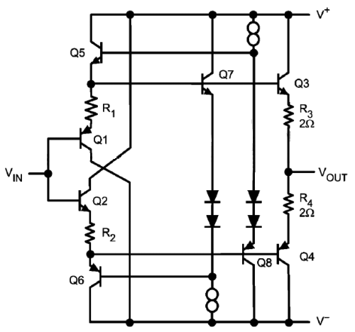
(The actual circuit is more complex, but I erased the protection diodes to make the topology more readily apprehensible.) Each output transistor gets its own three-transistor, push-pull, driver stage. These elaborate topologies are necessary in an OpAmp, as it is impossible to include large-valued capacitors within the OpAmp's small plastic package. On the other hand, if we build up a diamond buffer out of discrete transistors and resistors, we can add as many big electrolytic capacitors as we please. Indeed, just adding one big electrolytic capacitor makes a big improvement in the diamond's performance.
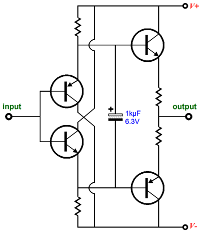
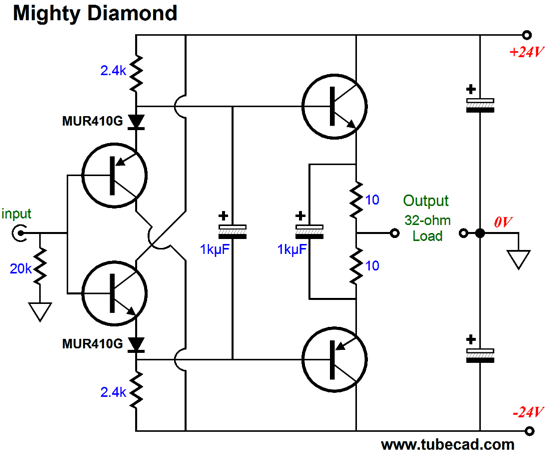
This added capacitor effectively transforms the input stage into a push-pull one, as the 1kµF capacitor effectively ties the two emitters together, so both input transistor work as a team to to drive the output transistors. Still, even after this modification, the diamond does not completely please; it still needs improvement. My reasoning was that the problem lay in the class-AB operation and that when one output transistor cut off, the diamond's output impedance doubled, causing a glitch in the output waveform, which the ear hears as scratchy sounding. I then set about fixing the problem with elaborate topologies. Some of them actually worked. See Blog 177 for more details. After much experimenting, I found a simple solution: one more capacitor.
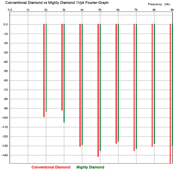
The added capacitor, in AC terms, shorts the two output transistor emitters together, so even when one transistor cuts off, the output impedance remains fairly constant, about 5 ohms. Wait a minute, what about the gm-doubling effect of the output transistors? Well, the effect is still there, but it is so small compared to the 10-ohm emitter resistor resistances that it is swamped out of the equation. In other words, the output transistor emitters present so low an output impedance that halving it when both are conducting, say 0.05 ohms, and switching to 0.1 ohms when only one conducts, makes little difference when added to the 5-ohm resistance. For example, 5.05 ohms versus 5.1 ohms is not as startling to the ear as 5.05 ohms versus 10.1 ohms without the extra capacitor. Okay, it's interesting but does it work? The answer is not an easy one to give. Here is an example, the following graph shows a SPICE simulation Fourier graph of the conventional diamond versus the Mighty Diamond, with all the same parts except for the two added capacitors, which define the Mighty version.
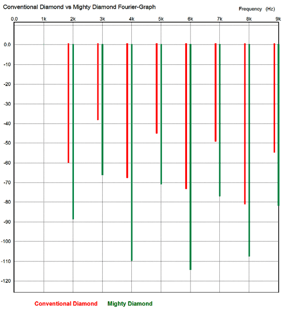
The circuits were required to put out 1Vpk into 32 ohms at 1kHz. Except for the third harmonic, the conventional diamond circuit wins this battle. Well, at least in terms of total harmonic distortion. But if we ignore all the harmonics above the third, the Mighty Diamond presents a much more ear-pleasing ratio of second and third harmonics. Remember the ear quite likes a bit of second harmonic and quite dislikes the third, as it lends a dead, lifeless, compressed quality to the music. In fact, if we look at just the 2nd, 3rd, 4th, and 5th harmonics of the Mighty Diamond, we would conclude that the circuit must be a single-ended one. If we stress these diamond buffers into swinging much bigger voltages, say 8Vpk, we see an altogether different picture.
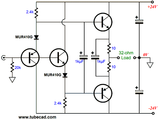
Now the tables turn. The Mighty Diamond produces less than 0.1% THD, whereas the conventional diamond, more than 1% THD. Which do you think will be more ear-pleasing? By the way, I showed this circuit to a friend last year, but in a slightly different form:
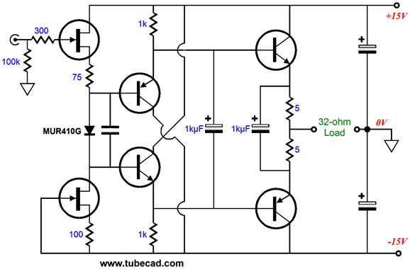
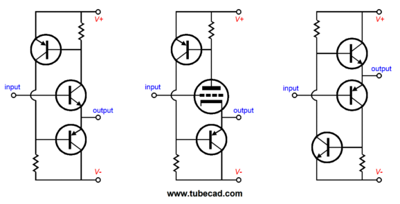
He was stunned by the novelty of the circuit. I didn't get it, as he acted as if he had never seen a diamond circuit before (he is an accomplished electronic designer). It turned out that my drawing it this way prevented him from seeing the diamond topology. Once I redrew the schematic with the two input transistors stacked in vertical line, collector leads crisscrossing, he saw the diamond topology. Interesting. I remember seeing a clever article in Popular Electronics or Radio Electronics magazine back in the 1950s that displayed mad, wild, strangely new topologies that weren't so. Common, basic, simple, well-known tube circuits were drawn in unconventional ways, preventing most readers from seeing the familiar topologies. (I was sure that the fellow who drew the schematics for Audio Research had been inspired by the article.) Okay, back to circuits. The MUR410G rectifiers are only there to function as voltage references, creating a bigger voltage drop across the the two 10-ohm emitter resistors. In other words, they are not essential; they could be removed altogether or replaced by two resistors. I had in mind building a headphone driver, so I included them to up the idle current flow, enriching the class-A envelope of operation. We could use a single rectifier, as the following circuit shows.
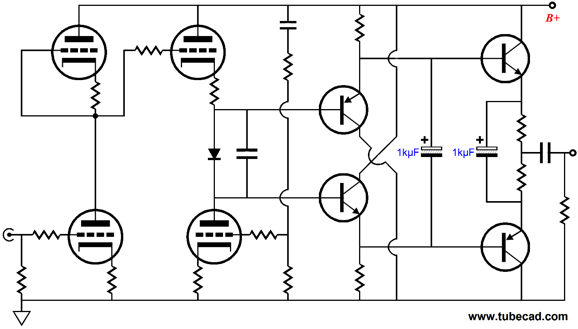
The FET-based input stage offers a nice single-ended touch and a high input impedance. Of course, the FETs could be replaced by two triodes, given a higher-voltage bipolar power supply. But to be honest, it would scare me a bit, as the transistors can easily damage the load if the tube is wiggled in its socket and loses contact. A safer approach would look more like the Moskido amplifier, which uses coupling capacitors to connect tubes to solid-state devices. Or, if the output saw a coupling capacitor, then we could Dc couple a tube stage, such as the Aikido directly to the Mighty Diamond buffer.
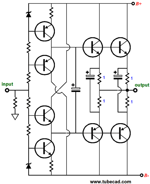
The single MUR410G provides about 0.5V of voltage drop, so we can drop the emitter resistor values to 5 ohms, decreasing the output impedance, for those who worry about such things. If we wish to build a truly powerful Mighty Diamond circuit capable of driving 8-ohm speakers, not 32-ohm headphones, then multiple parallel output transistors will be needed, each set getting 1-ohm emitter resistors and its own extra 1kµF capacitor.
Yes, it's a bit more complex, but the essential operation remains the same. The input stage works into constant-current sources instead of emitter resistors. The output impedance is about 0.25 ohms, in spite of the 1-ohm emitter resistors in the output stage. (Missing are bypass capacitors for the zener voltage references.)
Mighty Triadtron Diamond
The three-transistor Triadtron unity-gain buffer circuit was covered in blogs number 187 and number 188 and number 189.
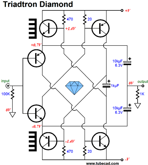
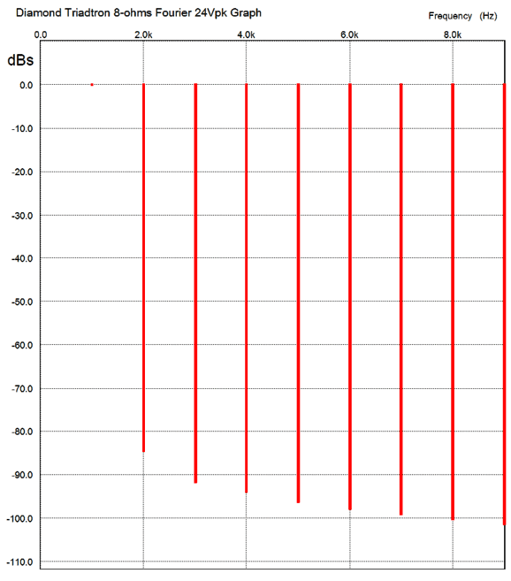
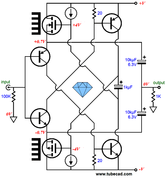
The Triadtron is a primarily single-ended topology, so two Triadtrons must be configured to allow true push-pull operation. The result is the above schematic. How well does it perform. In SPICE, the following graph shows that it works quite well.
The THD is less than 0.01% and the wattage is 36W into the 8-ohm load. Not bad. Be sure to note the transistors with heatsinks. They do the heavy work of driving low-ohm speakers. The rest of the transistors do the job of driving the output transistors and maintaining the desired idle current through these transistors. Also note how the output is actually not DC coupled but capacitor coupled, via the two 10kµF capacitors. Since so little voltage develops across these capacitors, they could be bypassed by 20-ohm resistors or two high-speed rectifiers in series. Of course, the output bipolar transistors can be replaced by power MOSFETs.
Next Time
//JRB |
I know that some readers wish to avoid Patreon, so here is a PayPal button instead. Thanks.
John Broskie
E-mail from GlassWare Customers
High-quality, double-sided, extra thick, 2-oz traces, plated-through holes, dual sets of resistor pads and pads for two coupling capacitors. Stereo and mono, octal and 9-pin printed circuit boards available.  Aikido PCBs for as little as $24 http://glass-ware.stores.yahoo.net/
Support the Tube CAD Journal & get an extremely powerful push-pull tube-amplifier simulator for TCJ Push-Pull Calculator
TCJ PPC Version 2 Improvements Rebuilt simulation engine *User definable
Download or CD ROM For more information, please visit our Web site : To purchase, please visit our Yahoo Store: |
|||


| www.tubecad.com Copyright © 1999-2012 GlassWare All Rights Reserved |