| John Broskie's Guide to Tube Circuit Analysis & Design |
|
Here is how I described the Aikido amplifier topology at its introduction:
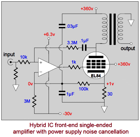
Then in blog number 13, I introduced an array of "Aikido" circuits that, once again, did not look like Aikido amplifier circuit of blog number 11. Thereafter, blog post after blog post displayed more "Aikido" circuits that didn't look alike. In fact, back in 1999, in the first article in first issue of the old-style webzine Tube CAD Journal, I explained how to design a tube-based "Aikido" cascode stage, although I didn't use the Aikido label. In the April/May 2001 issue, I revealed an amazing hybrid amplifier that used an OpAmp frontend and a single-ended tube output stage, standing the hybrid convention on its head, which also offered autobias. I described it thus: "Therefore, we have by injecting noise into the amplifier lowered the noise at the output: not Zen, but Aikido applied to electronics."
And in the last issue, I described an "Aikido" grounded-grid amplifier. And in my post on the Einstein's tube power amplifier back in 2006, I described my own Aikido-inspired amplifier for Einstein, which held three audio Aikido techniques, including a clever Aikido long-tail phase splitter. Moreover, I have explicated two different Aikido cathode followers. Indeed, the whole of my 2001 article, Totem-Pole Output Stage PSRR Enhancement, deals with Audio Aikido techniques applied to OTL circuits. (Unfortunately, I made use an odd schematic symbol, a square with a capital N inside to denote either a triode, a pentode, a N-channel MOSFET, or a NPN transistor, which few understood that it represented either a triode or a pentode or..., which confused many. We alter convention at our peril.) Many different circuits, but only one name: Aikido. How is this possible? Surely there can be only one Aikido circuit? No, not at all. Audio Aikido is a family of many electronic techniques that all share the same characteristic: the power-supply noise is used against itself, rather than relying on brute force techniques, such as using huge, massive inductors and Foster-beer-sized capacitors or complex high voltage regulators to purge power-supply noise at its source—or using tons of negative feedback within the amplifier to reduce the power-supply noise after the fact, i.e. once the noise has already leaked into its output. All of which leads us to the question, Why do I use the "Aikido" label and just what is Aikido?
Aikido History
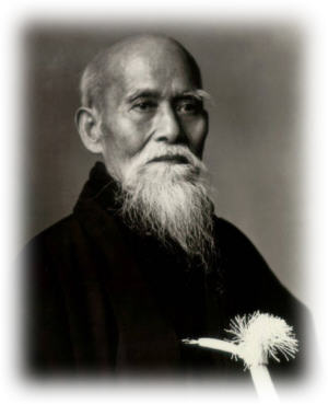
Originally, this martial art was named "Aikijutsu," but in 1942 its name was changed to "Aikido." From Wikipedia, we learn that he word "aikido" is formed of three kanji:
Thus "Aikido" translates to something along the lines of the way of joining with the spirit, the energy. As you can guess from its name, Aikido is more than just a martial art, as it is also a religious philosophy, one that compels an ethical treatment of one's attacker; so, unlike many other martial arts, gratuitous maiming and, indeed, killing one's opponent are forbidden, not on legal grounds, but ethical, spiritual ones. I first encountered Aikido when I was a young teenager. I had found a beautiful Japanese book on Aikido in a used bookstore, which I still own (somewhere in a box in my garage). Its binding was the first thing to catch my eyes, as it was covered in coarsely woven white cloth. I read the book with great interest and with much suspicion, as much of what it said seemed too metaphysical for my tastes. To my surprise, the techniques described in the book actually worked. One demonstration of the importance of the mental (spiritual) aspect of Aikido was giving by having a subject hold his arm out straight, with complete rigidity, locked tightly against being bent. Then, with not that much effort, I would bend his arm. So much for brute force. Next, he was told to loosely hold his arm out straight and to imagine that his arm was a fire hose and that a furious torrent of water rushed through it; now, his arm could not be bent. Not by me, not by anyone else.
(While I was in college, I made this demonstration before a group of friends, which including a thickly muscled Taekwondo student. He was brute force personified and he wasn't about to let me bend his arm. At time I was bulked up enough (and taller) to make the match fair. He was not short of mental energy, as he quickly summoned an instant anger and a fierce stubbornness to his aid, nonetheless I was still able to, after almost a full minute of strenuous effort, bend his arm back. As my hand pulled away from his skin above his elbow, his blood was revealed; the pressure had been so great that some of his blood had transpired through his skin, leaving my fingerprints in red. I have to admire such stubbornness, so stupendously stupid, so perfectly male.) The key aspect of the Aikido martial art is that it uses an opponent's force against him. The key aspect of Audio Aikido electronic techniques is that they use the power-supply noise against itself, obtaining a null at the output. Confusion, I hope, diminishes.
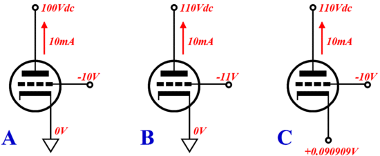
Aikido Single-Ended Output Stage I knew that I had to come up with a way of nulling the power-supply noise from the output stage's output. The key word in the last sentence was "output." Many have terminated a negative feedback loop at the output tube's plate, which indeed will lower the distortion and output impedance, but at the expense of a worse PSRR. Remember, we do not want the loudspeaker to see any of the power-supply noise and that the speaker does not attach to the plate, but the transformer secondary. This means that the output transformer must not see any power-supply-noise induced current variations, which means, in turn, that the output tube's current conduction must remain independent of any perturbations in the power supply's voltage. In other words, at idle, the output stage must draw a steady current, in spite of the noise riding on the B+ voltage. Because of the triode's relatively low plate resistance, how is a constant current draw possible? If the plate voltage increases, then so too must the triode’s current conduction; if this voltage decreases, then so too will its conduction. In other words, the plate resistance acts like a resistor placed across a varying voltage. Thus, the only way we can assure that a triode’s conduction is immune to power-supply voltage fluctuations is by varying either the grid or the cathode voltage in sync with the power-supply noise. But by how much? By definition, a triode’s amplification factor (mu or µ) is a measure of its grid’s effectiveness over its plate in controlling current flow. Thus, for example, if a triode’s mu equals 10, then a positive 10V increase in plate voltage can be countered by decreasing its grid voltage by -1V, as ΔVp/mu = Δ-Vg for a fixed current. (Do not be frightened by the Δ symbol; it stands for the delta, the change in a variable, in this case, for a change in either plate, grid, or cathode voltage, depending on the variable symbol that follows it.) Or, we could restore the same current draw by meeting the 10V increase in plate voltage by increasing the cathode voltage by 1(mu + 1), or by 0.090909, which equals 10V/11, as ΔVp/(mu + 1) = ΔVk for a fixed current.
Why the different formulas for grid and cathode? The answer is that the cathode is slightly more effective than the grid in controlling plate current; with a high-mu triode, such as the 12AX7, this makes little difference, as 101 versus 100 is not a big difference; but with a low-mu, such as a 6AS7, the difference is huge, as its mu equals a paltry 2 and 2 versus 3 is a large difference. The cathode's effective amplification factor is equal to mu + 1. Thus, the power supply noise must be divided by mu + 1, if applied to the output tube’s cathode, which means that some sort of voltage divider will be needed. My suggestion is that an identical triode be used as part of the voltage divider, as a triode’s mu is not nearly as constant as many imagine, varying as it does with changes in plate voltage and current. The additional triode will also come in handy by offering a low-output impedance at its cathode for driving the output tube’s cathode. Moreover, the input triode works in anti-current phase to the output tube. As the input triode draws more current, its cathode pulls up in voltage, which effectively makes the output triode's grid more negative relative to the its cathode, decreasing its conduction. And since no triode is perfectly linear, being easier to turn on than to turn off, the two departures from linearity tend to cancel. The trick to making this magic happen lies in using a constant-current source to load the input triode’s cathode, as the constant-current source will force the input triode do the required voltage division to maintain a fixed idle current for us. A cathode resistor, on the other hand, would not yield the desired 1/(mu + 1) ratio, as it would define a two-resistor voltage divider with the input triode. On the other hand, a cathode resistor could lower the distortion, but at the expense of a worse PSRR.
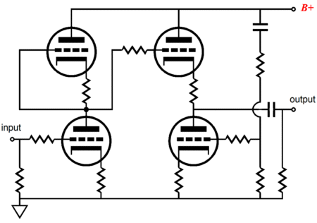
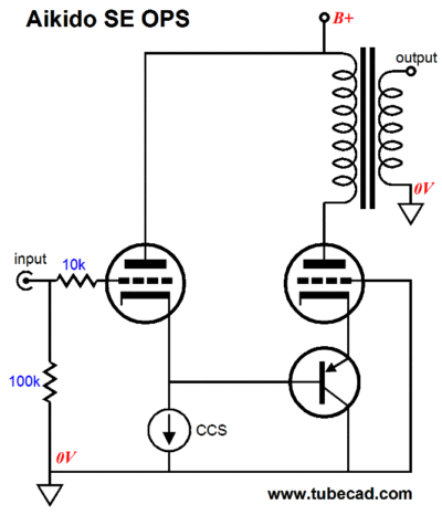
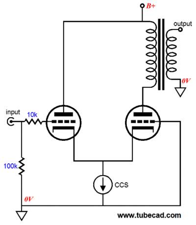
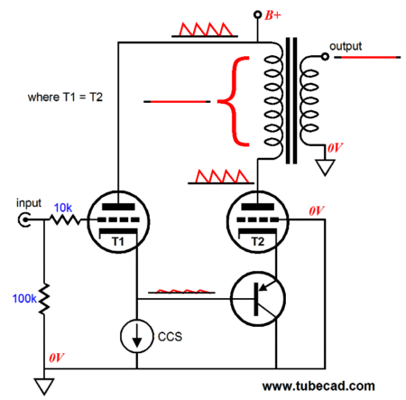
In the above schematic, we see the left triode receiving the input signal and the PNP transistor relaying the signal to the output tube’s cathode. Note that that this is a capacitor-free output stage. Wait a minute, why not just directly tie the two cathodes together and lose the PNP transistor?
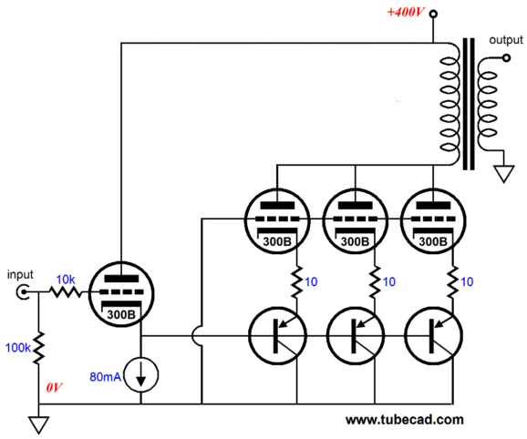
Indeed, such a setup would work perfectly—for just two power tubes, but what happens if two or more output tubes are used in parallel? For example, if three 300B were used in parallel as output tubes, then three 300Bs would be needed as input tubes. Ouch, that's expensive. In contrast, with each 300B getting its own PNP transistor, only one 300B would be needed as the input tube.
I tried to keep the schematic as simple as I dare, but the three 10-ohm resistors were too compelling to leave out. Why are they there? Adding a 10-ohm cathode resistor to each output tube's cathode helps prevent current hogging (an unequal sharing of current between the output devices) and, to a small extent, helps prevent oscillations. (I would also add three 10-ohm plate resistors and three 1K grid-stopper resistors.) But before we get to carried away with actual power amplifier design, let's return to the basic topology and make sure we understand how it works.
If everything works in our favor, the output tube's plate will hold exactly the same amount of power-supply noise as the B+ connection at the top of the output transformer; thus, preventing the output transformer from seeing any signal to transfer to the loudspeaker. Note how the constant-current source directly sets the input tube's idle current and indirectly sets the output tube's idle current. Of course the 0.7V voltage rise from emitter to base on the transistor must be factored in; but then, so too, must be the voltage drop across the output transformer's primary, which can be substantial. A primary's DCR can run from a low of 100 ohms to high of 1kohm, depending on the output transformer. In general, the higher the primary impedance, the higher the DCR, as higher winding ratio is required (assuming an 8-ohm loudspeaker as the intended load impedance). Okay, have we arrived? Is this the perfect single-ended output stage design? What do you think my answer will be? Yes? Not likely. No, we still have more work ahead of us. For example there's the issue of maximum cathode swing and maximum output power. In other words, will the input tube's cathode be able to swing big enough voltage swings to drive the output tube to full potential output power? Assuming that a solid-state constant-current source is used, rather than an inductor with a high DCR or a solid-state constant-current source with a negative power supply rail, we will not be able to deliver the full potential voltage swing that the input tube's cathode voltage seems to imply. I just gave away two possible workarounds: an inductor constant-current source or a solid-state constant-current source with a negative power supply rail.
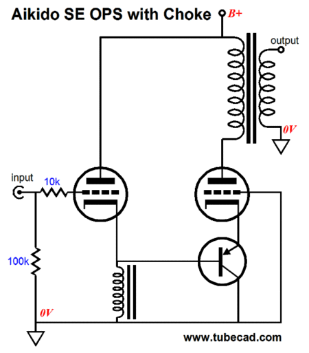
Over a limited frequency band, an inductor acts much like a constant-current source, except that it is set to any fixed current. In other words, if an inductor experiences a DC current of 80mA, it will behave much as a solid-state or tube-based constant-current source would in an audio circuit. A perfect inductor displaces zero DC voltage, but a perfect anything is almost impossible to find. Real inductors (chokes) are made with wire, wire which offers resistance. A choke's DCR is the DC resistance that the wire presents. Take a VOM and measure a few chokes and you will probably find a wide range of resistance values. Thus, with a little effort, we can find a choke whose DCR matches the cathode resistor value we need to bias up the input triode in our Aikido grounded-grid amplifier. If the exact value cannot be found, we can place make-up resistor in series with the choke. For example, say we need 450 ohms, but our closest choke comes in at 350 ohms, then we would place a 100-ohm resistor in series with it.
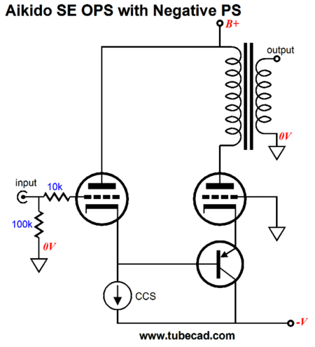
A negative power supply rail buys us more headroom, which would allow the output tube(s) to be fully driven up to twice the idle current and then down to cutoff. As little as -5Vdc may be all that is needed to ensure that the constant-current source's drop-out voltage is not encountered and that the PNP transistor has a big enough voltage window in which to function without cutting off. By the way, do not forget that it is harder to turn off a triode than it is to turn it on, so this topology works quite well with the triode's nonlinearity, as the PNP transistor's emitter can swing much higher up than down in voltage, ensuring that the output tube's cathode can be made sufficiently positive to fully turn off the output tube. And note that the option of running into positive grid voltage is an easy one to opt for in this topology, as the cathode is driven, not the grid; the grid, being grounded, can draw as little or as much current as it needs without tumbling the input tube. The biggest problem with using a negative power supply rail is that many tube fanciers just do not do negative power supplies. Why not? Well, for one they usually preclude using tube rectifiers. Moreover, many power transformer do not include the secondary taps required to create a negative power supply rail; so an additional power transformer will be needed, albeit, a much smaller transformer. Additionally, many just do not feel comfortable with negative voltages. This leads us to the possibility of creating a faux negative voltage by using a coupling capacitor and a resistor-based voltage divider.
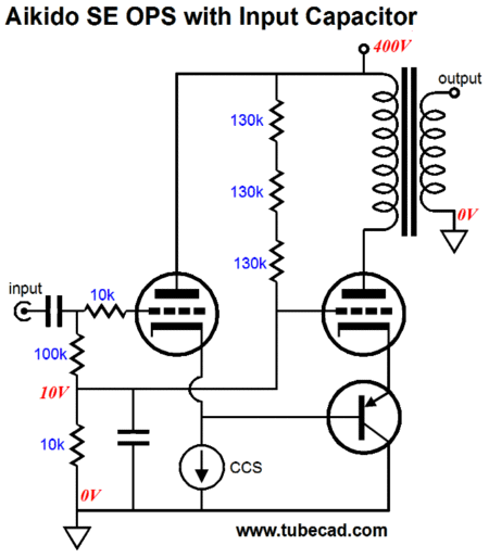
By adding the coupling capacitor at the amplifier's input, we leave the world of capacitor-free amplifiers, but then, few would be willing to own a power amplifier that required up to 80Vpk of input signal, besides a coupling capacitor probably already was in the signal path prior to the power amplifier. For example, I myself would like to build the following amplifier based on two Aikido topologies: an Aikido amplifier as the input stage and an Aikido grounded-grid amplifier as the output stage.
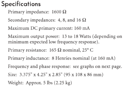
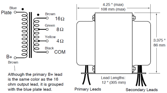
The EL34 output tubes are both fairly inexpensive and ear-pleasing, particularly when triode-connected. The One Electron output transformer, model UBT-1, is a gem. It presents a primary impedance of only 1600 ohms and benefits greatly from this low winding ratio.
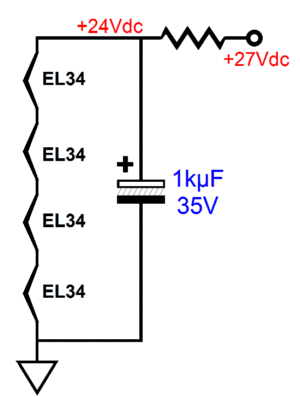
With three EL34 output tubes and an idle current of about 160mA, we can expect about 15W of single-ended glory. (Many tube amplifier companies have reverted to using peak watts in describing their amplifier; I am not so shameless.) Note that the input EL34 tube does not draw as much current as each of the three output EL34 tubes do. Why not? Because this tube sees slightly more cathode-to-plate voltage (no primary DCR voltage drop) and runs slightly leaner, it will create a higher cathode voltage, which buys us more voltage headroom within which to run the constant-current source and the three PNP transistors. The constant-current source could be made from discrete solid-state devices or, if you are lazy, from an LM317-HV and one resistor. The Aikido amplifier input stage holds 12AX7 and 12AU7 tubes, but a hundred other combinations would work as well, say a 6072 and 5687, sticking to industrial tube numbers. The only thing that I don't like about this design is that one could easily imagine the amplifier was a push-pull type, as that is what four EL34 tubes seems to imply. Of course, other gain stages could be used at the input and other output tubes and other output transformers could be used. I haven't mentioned which PNP transistors should be used, mostly because I do not believe they are that big a deal. I would use the MJE15033G. Why? Well, I own a bunch of them for one and their 250V rating cannot hurt. They are 50W TO-220, three pin devices and they cost less than $1 each. In addition, this PNP transistor collector attaches to the TO-220 tab, so it could even be attached directly to the chassis, not that I would recommend doing so. Although rated 50W, without a heatsink @25°C, its maximum dissipation is only 2W, if memory serves me correctly. (Always read the datasheet carefully before using an electronic device.) And do not forget that it gets plenty hot inside the chassis of a tube amplifier, so some form of heatsinking is probably required, even if it is only a length of aluminum bracket. It all depends on the output tubes used, the resulting voltage drop across the transistor and the current flow through it.
Danger, Danger!
Next Time
//JRB |
|
I know that some readers wish to avoid Patreon, so here is a PayPal button instead. Thanks.
John Broskie
E-mail from GlassWare customers:
And
High-quality, double-sided, extra thick, 2-oz traces, plated-through holes, dual sets of resistor pads and pads for two coupling capacitors. Stereo and mono, octal and 9-pin printed circuit boards available.  Aikido PCBs for as little as $20.40 http://glass-ware.stores.yahoo.net/ Only $12.95 TCJ My-Stock DB
Version 2 Improvements *User definable Download or CD ROM www.glass-ware.com |
||


| www.tubecad.com Copyright © 1999-2011 GlassWare All Rights Reserved |