| John Broskie's Guide to Tube Circuit Analysis & Design |
19 March 2016
Balanced Circuits
In the last post, we covered the Other Circlotron topology. It, like all other Circlotron circuits, is a balanced design, which accepts a balanced pair of anti-phase input signals and delivers a balanced output signal into the external load. Since loudspeakers are free-floating loads, they can attach to either balanced or unbalanced outputs.
Most headphones, however, are terminated with the famous three-contacts plug, which means that they must be used with an unbalanced signal source, as both drivers share a common ground connection; alas. Switching the headphones to a four-pin connector often improves the sound, even when used with unbalanced headphone amplifiers. How is that possible? Better grounding practice.
But as most power amplifiers—most of which are unbalanced—can only accept an unbalanced input signal, what can we do to drive them from a balanced signal source? Well, we can convert the balanced pair of signal into a single unlaced signal with a signal transformer.
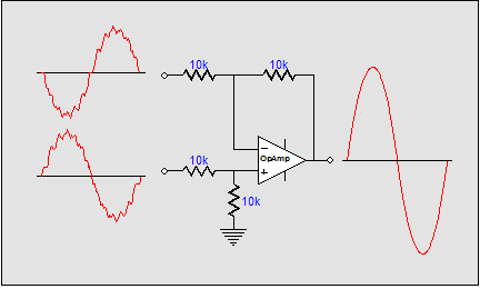
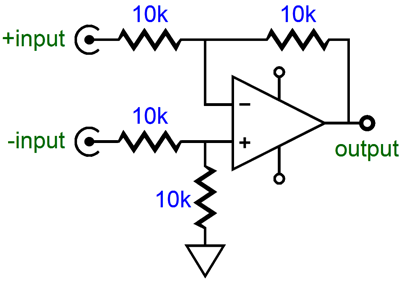
Transformers prevail when it comes to simplicity and breaking ground-loops. Unfortunately, good ones are quite expensive and rare. (If they could be had for under $10, there are scores of circuits that I would build that would exploit the transformer's advantages.) Or, if we are too budget constrained, we could use a simple OpAmp circuit to convert the two balanced signals into one unbalanced signal. (Unfortunately, this circuit often fails to sidestep the ground-loop problem, which is why signal transformers are still made and used. In addition, this circuit requires tightly matched resistors to realize its full potential.)
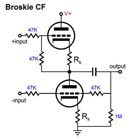
This simple circuit not only strips away AC common-mode noise, it strips away common, i.e. shared, DC voltages. What about a tube solution? Easy enough, we can use a Broskie cathode follower (BCF). See TCJ October 1999 and Blog number 192 and Blog number 239 for more information on this circuit.
No gain, but the two anti-phase signals become one unity-gain unbalanced signal. The Broskie cathode follower offers a low output impedance and true push-pull operation that allows more than the idle current to be delivered into the external load. Long ago, I received an e-mail from a reader who stated that he was using a 6DJ8-based Broskie cathode follower to drive his 300-ohm headphones. I was sure he was making a mistake; but before scolding him, I performed some tests. Dang, he was right: a 6DJ8-based BCF worked amazingly well with my own 300-ohm headphones. But what if we do not desire a low output impedance or big current swings? Well, then we can build the following circuit.
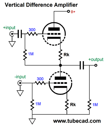
Vertical Difference Amplifier
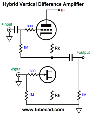
This vertical difference circuit rejects common-mode signals and passes the difference. With high-impedance loads it deliver a tad bit more than unity gain. It can be made with either FETs, MOSFETs, or transistors, the last woo of which will require more elaborate biasing configurations. Nonetheless, the principle of operation is the same: the with common-mode signals the top and bottom active device push and pull equally, resulting in a tie and no output signal. With diphasic, i.e. balanced, signals, the top device pulls while the bottom device releases is grip, thereby allowing the output to swing upwards. Conversely, when the top device releases its grip, the bottom device pulls downward, allowing the output to swing negatively. We could even create a hybrid vertical difference circuit, using a triode and a FET.
This will require some tweaking to get the highest common-mode rejection ratio (CMRR) possible. Nonetheless, it works in same fundamental way as the all-tube version does. In fact, if the B+ voltage is high enough and the triode's mu low enough, we could lose the input coupling capacitor, as the triode's cathode voltage might be high enough to allow the FET some operating voltage space. We could even add a hybrid Aikido cathode follower.
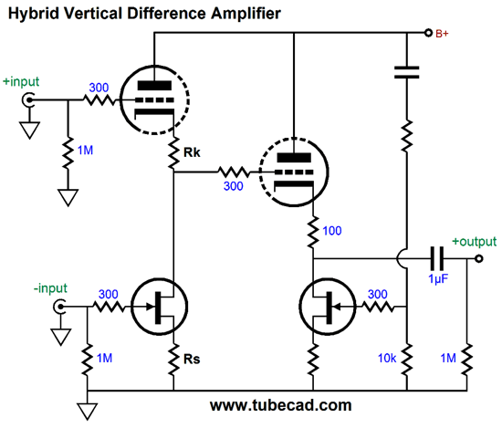
(I better stop right here, as I feel the urge to come up with many more variations on this topology.)
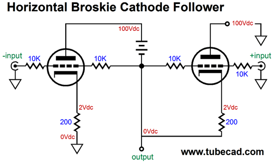
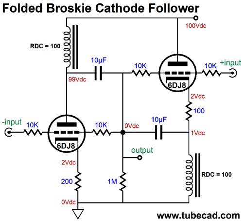
Horizontal Broskie Cathode Follower
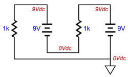
Yes, it does look odd. Where is the output coupling capacitor? Why is there a battery? If you squint your eyes and ignore the ground symbols, it looks something like a Circlotron. The secret to making sense of this circuit is to focus on the floating 100V power supply. Imagine a 100V battery, if you must, which is why I used that symbol, there being no symbol for a floating power supply. Indeed, let's imagine two household batteries and two resistors:
In fact, if you have two 9V batteries and two 1k resistors, assemble in actual deed the circuit shown above and measure the voltages. Once the light bulb turns on in your head, move on to the following circuit, which uses a single fixed power supply and two chokes.
The inductors (chokes) function like constant-current sources that only displace the voltage equal to the current flow through them against their DCR. In other words, the output can swing far beyond their 1V voltage drop. Note that normally these triodes would require a B+ of 200Vdc, but the two inductors allow us to fold the circuit into a 100V space. Now, let's replace one inductor with an output transformer.
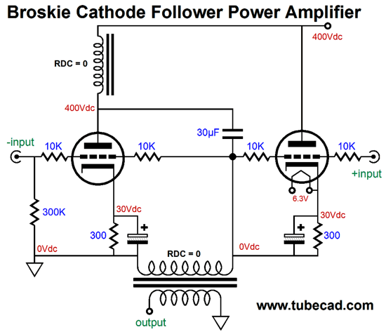
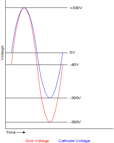
I know it label states "amplifier," but this is more of a power buffer, as the triodes create no voltage gain. I assumed huge voltage swings, which is why I showed the right triode getting its own floating 6.3V heater power supply or winding, as its cathode, unlike the left triode's cathode, will shift up and down in big voltage swings. The output transformer must hold an air-gap, as it will experience a sustained DC current flow. Many readers are thinking: Is this trip really necessary? And they are right to ask, as we could simply build a push-pull, cathode-follower output stage instead.
(Forgive the old schematic.) The huge problem that a cathode-follower output stage presents is the huge input voltage swings required to drive it to full output.
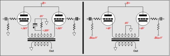
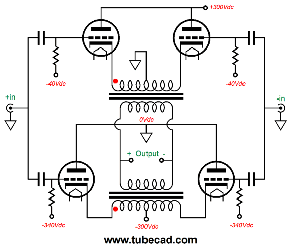
For example, although the output tube only sees a 300V cathode-to-plate voltage at idle, its grid might have to see near to 600Vpk-pk input signal. Is this the end of the world? No. One project that I have wanted to build for the longest time is a power amplifier with a cathode-follower output stage and the ability to drive electrostatic headphones, such as those made by Stax. In other words, when I want to listen to the headphones, I would rotate a knob which would switch off the output tubes and redirect the driver stage's output to the ES headphone jack. Since input and driver stages would require a bipolar power supply, we could double up on output tubes in the following way, although it would require a second output transformer.
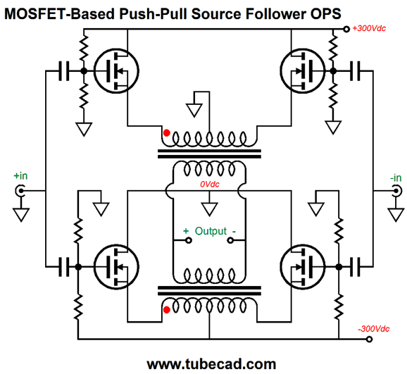
Because the cathodes swing huge voltages, each output tube would require its own heater winding. Yes, that means for per channel and eight for a stereo amplifier. Or, we could forgo the output tubes and use four high-voltage power MOSFETs.
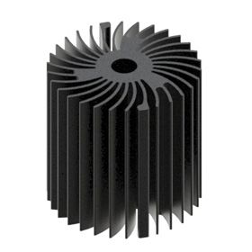
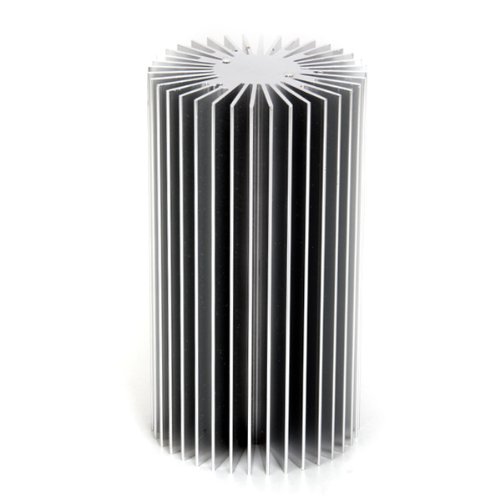
No heaters to worry about and potentially many watts. What is not to like? You can buy some fantastically cool-looking and performing LED heatsinks, which would look quite tube-like protruding from a chassis.
So, why did I show the Broskie-cathode-follower version? I did so to show what is possible; besides, you never know when such a topology might come in handy. Remember: you can never be too tall or too thin or too rich or too mentally flexible.
Next Time
User Guides for GlassWare Software Since I am still getting e-mail asking how to buy these GlassWare software programs:
For those of you who still have old computers running Windows XP (32-bit) or any other Windows 32-bit OS, I have setup the download availability of my old old standards: Tube CAD, SE Amp CAD, and Audio Gadgets. The downloads are at the GlassWare-Yahoo store and the price is only $9.95 for each program. http://glass-ware.stores.yahoo.net/adsoffromgla.html So many have asked that I had to do it. WARNING: THESE THREE PROGRAMS WILL NOT RUN UNDER VISTA 64-Bit or WINDOWS 7 & 8 or any other 64-bit OS. One day, I do plan on remaking all of these programs into 64-bit versions, but it will be a huge ordeal, as programming requires vast chunks of noise-free time, something very rare with children running about. Ideally, I would love to come out with versions that run on iPads and Android-OS tablets.
//JRB |
Kit User Guide PDFs
And
High-quality, double-sided, extra thick, 2-oz traces, plated-through holes, dual sets of resistor pads and pads for two coupling capacitors. Stereo and mono, octal and 9-pin printed circuit boards available.
Designed by John Broskie & Made in USA Aikido PCBs for as little as $24 http://glass-ware.stores.yahoo.net/
The Tube CAD Journal's first companion program, TCJ Filter Design lets you design a filter or crossover (passive, OpAmp or tube) without having to check out thick textbooks from the library and without having to breakout the scientific calculator. This program's goal is to provide a quick and easy display not only of the frequency response, but also of the resistor and capacitor values for a passive and active filters and crossovers. TCJ Filter Design is easy to use, but not lightweight, holding over 60 different filter topologies and up to four filter alignments: While the program's main concern is active filters, solid-state and tube, it also does passive filters. In fact, it can be used to calculate passive crossovers for use with speakers by entering 8 ohms as the terminating resistance. Click on the image below to see the full screen capture.
Tube crossovers are a major part of this program; both buffered and un-buffered tube based filters along with mono-polar and bipolar power supply topologies are covered. Available on a CD-ROM and a downloadable version (4 Megabytes). |
||


| www.tubecad.com Copyright © 1999-2016 GlassWare All Rights Reserved |