| John Broskie's Guide to Tube Circuit Analysis & Design |
21 December 2016 Post Number 365
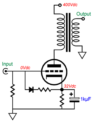
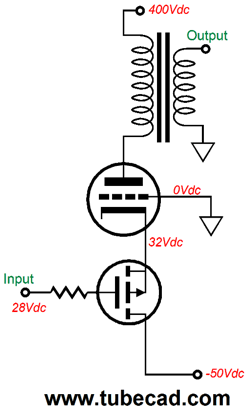
Class-A2 Single-Ended Amplifier Where to start? Imagine if a friend sent you the following schematic and asked for your comments.
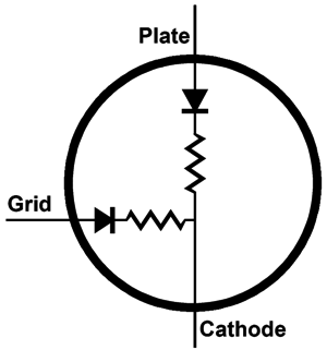
No doubt, your first response would be to query the need for the extra diode and resistor that span between grid and cathode. Indeed, you would worry that these extra parts will result in greatly increased distortion when the grid is driven positive relative to the cathode, as the diode will be forward biased and begin conducting, which will impose a much lower load impedance to the signal source. Well, your worries are well founded. The problem is that all output tubes actually incorporate these extra components inside their glass envelope, as they are intrinsic to the triode's functioning, although the schematics never show them. Indeed, we could have used the following triode symbol rather than the conventional one.
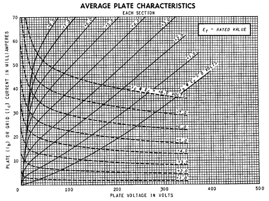
Since we don't use this symbol, you have to remember that the grid and plate define diodes with the cathode. You must also remember that the grid can draw a substantial amount of current, when driven positive relative to the cathode. Here is an example taken from the GE data sheet for the wee tiny 12AT7.
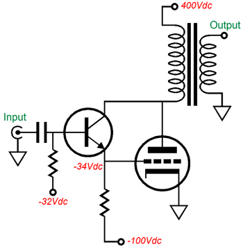
All of the grid lines shown are for zero and positive grid voltages, which explains why they don't look normal. The dashed lines reveal the amount of current drawn by the positive grid voltage. Note that the +8V grid line intersects the +8V grid-current line at 55mA! In other words, with a plate voltage of +35V and a grid voltage of +8V, the cathode will pass 110mA of current, with the plate dissipating 1.9W and the grid dissipating 0.44W of heat. Now, 8V divided by 0.055A equals about 145 ohms, so how well do you think the preceding stage will deal with this load impedance, when the negative-grid impedance was closer to 100M? Imagine a 12AX7-based driver stage. The horror. The workaround is to drive the grid positively with a DC-coupled cathode follower or source or emitter follower or use an inter-stage signal transformer. The cathode follower must be robust enough to pass the required grid current. In other words, a 12AX7-based cathode follower will not be of much use in driving a power output tube's grid positive. The inter-stage signal transformer must be driven by a robust driver stage, as it will relay the drastically lower positive-grid impedance to its primary, which if capacitor coupled, will prove a giant step sideways, as this capacitor will charge up, but cannot create blocking distortion, as the transformer cannot pass DC voltages, but the excessively charged up capacitor can throw off operating points in the driver circuit. In other words, although the inter-stage signal transformer will out perform a coupling capacitor, it is not a slam-dunk or easy-to-implement solution. Radio transmitters that used power triodes and that ran in class-A2 used a small power amplifier to drive the transmitting tube's grid. Note that the current drawn by the positive grid does not end up helping us drive the loudspeaker; it only subtracts from the single-end (or push-pull) amplifier's already low efficiency. One workaround has been offered that uses the grid current by sending it into the output transformer's primary.
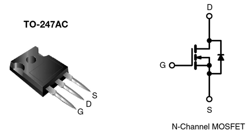
The obvious danger is toasting the NPN transistor. Do let the relatively low 400V B+ voltage fool you. The top of primary sees a fixed 400V, but the bottom end sees voltage swings down to 100V and up to 700V. And this is only under normal operation. Normal operation? Let's say the primary impedance is stated to be 3.2k. What does that mean? It means that if you connect an 8-ohm load to the secondary, the primary will reflect a 3.2k impedance to the output tube's plate. If a 4-ohm speaker is attached instead, the reflected impedance will be only 1.6k ohms. What happens if no speaker is attached? At idle, not much. While playing music, on the other hand, we face potential problems. Say the music is playing loud and someone steps on the speaker cables, momentarily breaking the speaker's connection to the amplifier. In that brief period of time, the primary can erratically swing thousands of volts, as the primary impedance has risen to near infinity. In other words, a 500V NPN transistor will die. MOSFET's, however, do offer a higher drain-to-source voltage. For about $25, you can buy a 3kV MOSFET, the IXTH1N300P3HV. For about twice as much, you can buy a 4.5kV MOSFET. In general, a 500V MOSFET will out survive a 500V transistor. Why? Almost all MOSFETs contain a protection diode that spans from source to drain. For example, the following was taken from the IRFPG40's data sheet.
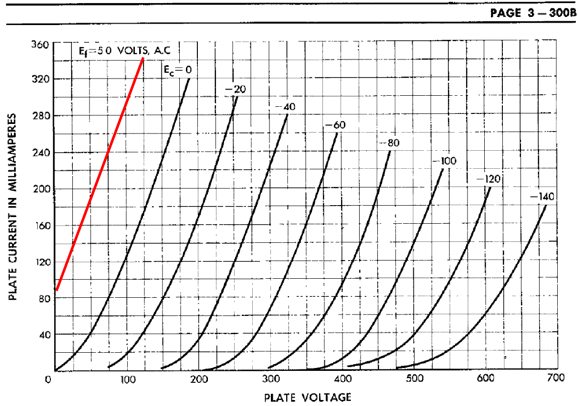
Note the diode in the MOSFET's symbol. Often the safety diode is shown with the zener symbol, which is appropriate, as the diode's breakdown voltage functions as a high-voltage zener. Why not use another tube to drive the grid? It's not a bad idea, but the tube must get its own floating heater power supply and it must be robust enough to pass the grid current. In addition, as the power tube's plate pulls down, its grid must be pulled positive. Thus, the driver tube will see a lower cathode-to-plate voltage than the power tube, which means that we run the risk of the driver tube entering positive grid voltage. In short, class-A2, whether in a single-ended or push-pull amplifier, requires much more thought than most expect. If we acknowledge and anticipate the severe load the grid will present, the rest of the class-A2, single-ended output stage is easy to design. Well, sort of. For example, I have never seen published the positive grid-lines for a 300B triode, which would come in handy in designing a class-A2 output stage. The workaround is to make them ourselves.
I drew a grid-line for +20V by matching the slope of the 0V grid-line and then offsetting it by the same distance that the -20V line is to the 0V line. Obviously, the further left it goes, the less accurate we can expect it to be. But as our concern is at the top of the line, it is accurate enough to use. The next step is to read my How to Design an SE Power Amplifier from post number 122. Here is a quick example, your high-voltage power supply puts out only 300Vdc, which is why you are thinking about using class-A2. You figure that you can idle at the 300B limit of 100mA, which means that with negative grid bias, the triode will only dissipate 30W of its maximum 40W of plate dissipation, or in other numbers 75%. The next step is to find where the +20V grid-line intersects the horizontal 200mA line, which appears to be at about 60V. Now, 300V - 60V is 240V, which divided by 100mA equals 2400 ohms, with 2.5k being close enough. We find the required bias voltage by traveling down the 100mA horizontal line until we hit 300V, which appears to be at about -55Vdc. There we have it. How many watts of output power can we expect? Well, 100mA squared against 2500/2 equals 12.5W. We can expect a tad less due to losses, such as primary and secondary DCR and core losses, so 10W to 11W would be a reasonable guess.
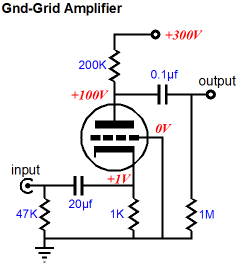
Class-A2 Ground-Grid Output Stage
We can lower the input impedance by replacing the cathode resistor with a constant-current source. Still, the impedance will equal (rp + Rload)/(mu + 1). Alternatively, we can use either PNP transistor or P-channel MOSFET to drive the cathode.
The above circuit prevents positive-grid current, by never letting the cathode become negative relative to the grid. In contrast, the following circuit will allow the grid to become positive relative to the cathode, as the MOSFET's source can fall below 0V.
If the MOSFET pulls the cathode below 0V, the grid can draw its current from its connection to ground. No big deal. The grid current is still wasted. Here is a workaround.
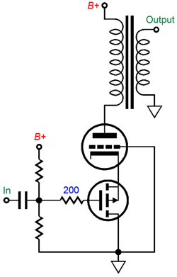
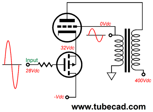
The N-channel MOSFET is configured as a source follower and its drain terminates into the triode's plate. Now, the grid current will flow through the MOSFET into the primary. Interesting, if a bit obvious. How about sending the grid current into the secondary, rather than the primary? Here is an example.
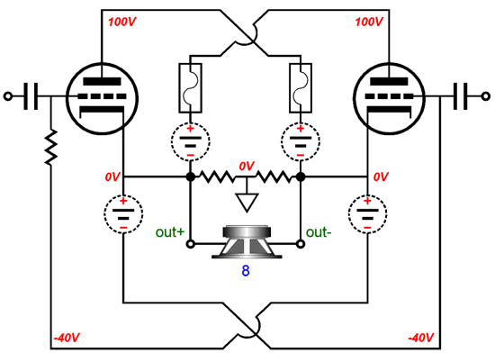
The grid swings in phase with the cathode, so a negative feedback loop is in place, which means that the cathode must see much larger voltage swings to bring the output stage to full power. What happens if the cathode voltage falls below the grid voltage? The grid will begin conducting current and the current will augment the secondary's negative swing. Of course, not by that much, but at least the grid will not be wasted. Even if we terminate the MOSFET's drain into ground, not a negative voltage, this circuit is interesting. For other grounded-grid single-ended design ideas of a class-A1 nature, see post number 220, where you find this circuit.
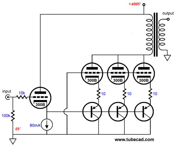
The above single-ended output stage employs my Aikido mojo, as the input cathode follower will inject 1/mu amount of power-supply noise into the three grounded-grid amplifier cathodes, which will result in nulling the power-supply noise at the secondary. There was a time when I would not dare show such an extravagant design, but now that we live in an age of 1W OTL power amplifier that use four 300B output tubes, this design seems almost beer-budget. On the other hand, with the right output transformer, we can expect to get 25W (or more) from the above amplifier, which means that we are only paying about $20 per watt, assuming $125 per 300B; a real bargain compared to the $500 per watt we would pay with the 1W OTL. Bear in mind that the above circuit is only the output stage and that an input stage (and maybe a driver stage), which will be needed, and which post number 220 just happens to show.
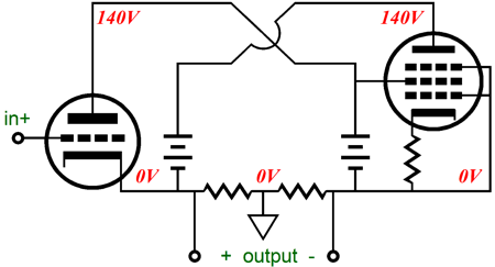
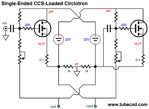
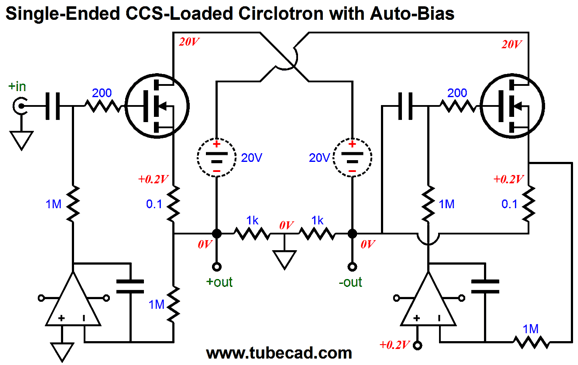
Single-Ended CCS-Loaded Circlotron
The following is a simple, MOSFET-based, single-ended Circlotron that idles at 2A, so 16W into 8-ohm loads is possible, as the peak output current swing equals the idle current in a current-source-loaded single-ended output stage. Dang it, John, why MOSFET? Why not use a 2A3 or 211 or some other DHT tube instead? If an output transformer or autoformer is used, then sure use 45 or 845 tubes. Without the intervening iron, however, these will only provide at best 1/20th of the needed current. For example, a 300B published current limit is 100mA, so 20 would be needed to get to 2A. On the other hand, just two 300B output tubes configured as a cathode follower, working into an output transformer, would deliver the same 16W of single-ended output. MOSFETs, in contrast, are cheap, rugged, and plentiful. In addition, by running so high an idle current we never run into the foggy-sonic perspective that some find so irksome about MOSFET-based amplifiers.
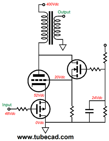
The two floating 20V power supplies should be rated for at least 4A of current flow. No signal gain is provided, so a hot balanced line stage or an internal input and driver stage will be needed. The two potentiometers set both the idle current and the DC offset. They are configured in a garter-belt setup, where a DC offset naturally tends to correct itself. Here is an all-tube version.
A nice feature to add would be an auto-bias and DC offset servo. Class-A operation makes it easy. Here it is.
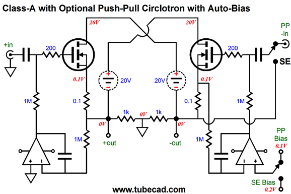
The left OpAmp corrects the DC offset, while the right OpAmp establishes the desired idle current flow. The OpAmps must be powered by a ground-referenced bipolar power supply, say +/-15Vdc. Long ago, a TV commercial sang, "Sometimes you feel like a nut, sometimes you don't." Verily, verily. Truer words have probably been uttered, but I've never heard them. Well, sometimes you feel like single-ended, sometimes you feel like push-pull.
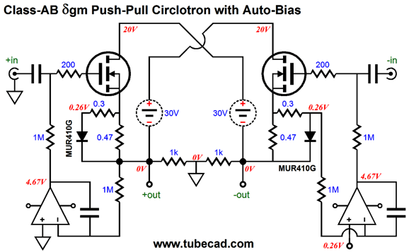
I didn't draw the dashed line between the two switches, but the two work in unison. Now that I look at it, I see that the bottom switch's contact should attach to a small-valued capacitor to ground, say 0.1µF. Although a bit off topic, here is a class-AB Circlotron with a constant-transconductance output stage, the result of including the two 0.43 resistors and two rectifiers. Since these rectifiers effectively clip the DC signal sent to the right OpAmp, we can implement an auto-bias scheme in spite of the class-AB operation.
Why the lowercase Greek delta character in the title? I have seen underscored (or was it an over-scored) symbols used in old electronic textbooks to denote a variable being held constant, but that can mean "the average of."
I remember Richard Feynman using the small-case delta to denote that a variable was being "held constant," thus,
Returning to this circuit, in theory, the 0.3-ohm resistors should match the 0.47 source resistors. They do not, as the rectifier exhibit an internal resistance of about 0.2 ohms. Since the rectifiers begin conducting at 0.52V, we set a 0.26V voltage drop across the 0.47-ohm source resistors at idle, which imposes an idle current of 554mA, which means that each MOSFET must dissipate 16.5W. Although this much heat is nowhere near class-A standards, it's plenty toasty.
//JRB
If you have been reading my posts, you know that my lifetime goal is reaching post number one thousand. I have 635 more to go. My second goal is to gather 1,000 patrons. I have 976 patrons to go. If you enjoyed reading this post from me, then you might consider becoming one of my patrons at Patreon.com.
User Guides for GlassWare Software
For those of you who still have old computers running Windows XP (32-bit) or any other Windows 32-bit OS, I have setup the download availability of my old old standards: Tube CAD, SE Amp CAD, and Audio Gadgets. The downloads are at the GlassWare-Yahoo store and the price is only $9.95 for each program. http://glass-ware.stores.yahoo.net/adsoffromgla.html So many have asked that I had to do it. WARNING: THESE THREE PROGRAMS WILL NOT RUN UNDER VISTA 64-Bit or WINDOWS 7 & 8 or any other 64-bit OS. I do plan on remaking all of these programs into 64-bit versions, but it will be a huge ordeal, as programming requires vast chunks of noise-free time, something very rare with children running about. Ideally, I would love to come out with versions that run on iPads and Android-OS tablets. //JRB |
Kit User Guide PDFs
E-mail from GlassWare Customers
High-quality, double-sided, extra thick, 2-oz traces, plated-through holes, dual sets of resistor pads and pads for two coupling capacitors. Stereo and mono, octal and 9-pin printed circuit boards available.  Aikido PCBs for as little as $24 http://glass-ware.stores.yahoo.net/ Support the Tube CAD Journal & get an extremely powerful push-pull tube-amplifier simulator for TCJ Push-Pull Calculator
TCJ PPC Version 2 Improvements Rebuilt simulation engine *User definable
Download or CD ROM For more information, please visit our Web site : To purchase, please visit our Yahoo Store: |
|||


| www.tubecad.com Copyright © 1999-2016 GlassWare All Rights Reserved |