| John Broskie's Guide to Tube Circuit Analysis & Design |
21 December 2010
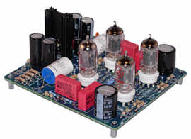
PCBs At Last!
Split-Load Phase Splitter
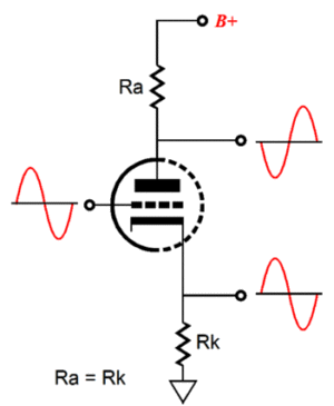
The split-load phase splitter (AKA cathodyne phase splitter) receives an unbalanced input signal and delivers a balanced output signal. It provides a differential gain close to 2 and a single-phase gain close to unity. It is actually just a variation on the grounded-cathode amplifier that stipulates equal values for the cathode and plate resistors. Both resistors are AC grounded at one end, at ground and at the B+ connection, and output is taken from the resistor's other end. Since both resistors are in the same current path, each must experience the same voltages swings as the other, which ensures this phase splitter's fabulous balance. Symmetry is all important here. Each phase output must see the same load impedance, otherwise the balance is lost. Another design issue is getting the idle current right. From blog post number 167 the following summery is worth repeating:
One potential problem we face when using the split-load circuit is its vastly differing PSRR figures at its outputs. The output taken from the plate holds almost all of the power supply noise, while the output taken from the cathode holds almost none.
Of course, if the B+ contributes no power-supply noise, then the dissimilar PSRR figures would not be an important design consideration. In the real world, this discrepancy must be addressed, as the power-supply noise will get amplified further down the signal path. Ideally, a phase splitter would completely reject the power-supply noise. Second best, it would present equal power-supply noise at each phase output, equal in amplitude, equal in phase; thus, the push-pull output stage could apply its CMRR to this common-mode signal and reject much of it from the amplifier's output.
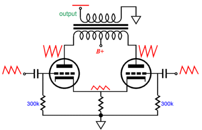
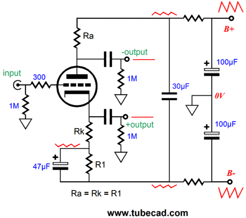
One problem with this approach is that a push-pull output stage's CMRR is not as constant as most imagine. At idle, with both output tubes conducting equally, the output tube and output transformer work to reject what is common to balanced input signal; true enough. But when in use, playing music, when one output cuts off, the remaining on output tube simply treats the common-mode noise signal as signal, as something to amplify. (I am convinced that this a major part of explaining why class-A amplifiers sound so much better than class-AB amplifiers.) Or what if the spilt-load phase splitter's output delivers signal to an unbalanced device, with the phase splitter only providing a choice between phases? In this situation, there is no CMRR, as the input signal is effectively unbalanced? For example, the following spilt-load phase splitter offers two-phase outputs and largely rejects power-supply noise.
The assumption behind this circuit is that the bipolar power supply develops equal but out-of-phase power-supply noise on both rails, which the spilt-load phase splitter exploits to null the noise from its two outputs.
I used a variation on this topology in my "Phase Selection & Zero Gain Line Stage Amplifier" back in 1998 at the GlassWare website.
The goal was a unity-gain line-stage amplifier (buffer, actually) that offered phase reversal. (A friend fell in love with my prototype and he still uses it to this day. I used a large-valued polypropylene power supply capacitor that bridged both power supply rails, which helps make this line-stage amplifier almost ageless. In addition, he runs it without an output coupling capacitor, as the output DC offset is low and his tube power amplifiers are indifferent to the few millivolts of offset voltage.) Here the decision was to add an input coupling capacitor so that the extra cathode resistor and its electrolytic bypass capacitor could be left out of the circuit.
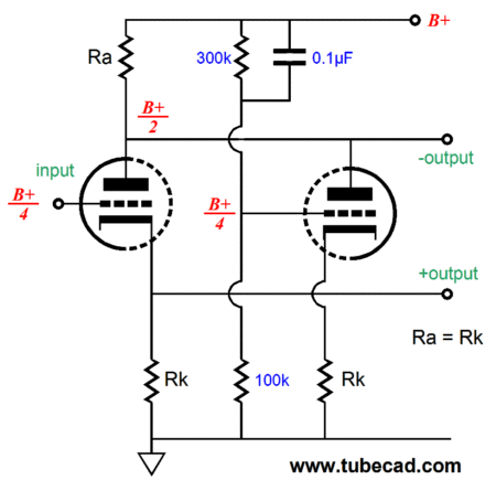
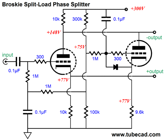
Broskie Spilt-Load Phase Splitter
The left triode functions as a simple spilt-load phase splitter; the right triode, as a noise canceller. When the right triode sees voltage perturbation at its grid, it takes that input signal and inverts at its plate, thereby nulling the perturbation from the phase splitter's inverting output. The phase splitter's non-inverting output also benefits, as the right triode never sees the power-supply noise, so it cannot pass any of it along at its non-inverting output. Clever, don't you think?
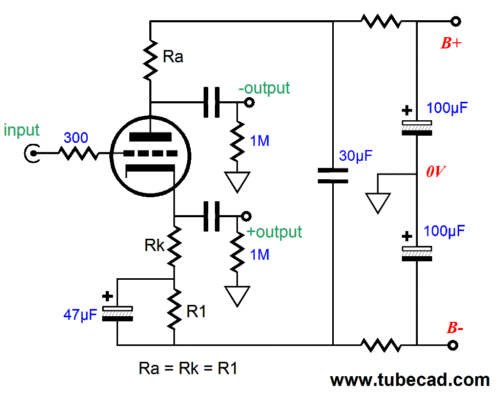
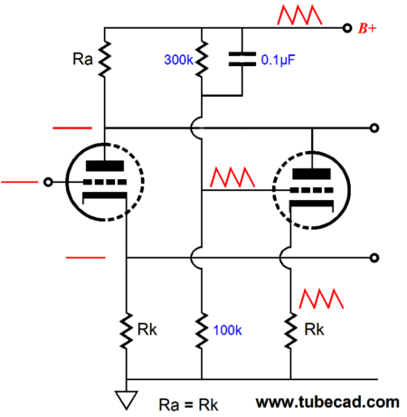
Once you have the concept down pat, you can move on to the actual circuit implementation shown below.
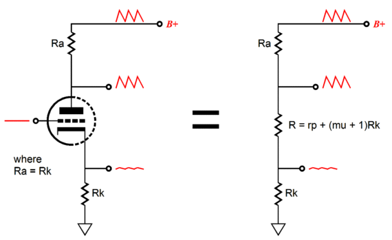
The two-resistor voltage divider (300k & 100k) quarters the B+ voltage nicely and the diode protects the right triode at turn-on, when the tube is cold and not yet conducting; but its grid is at the B+ voltage, while its cathode is at ground potential. Why is a 9.6k cathode resistor used for the right triode and not a 10k resistor? If the right triode provided true unity-gain at its cathode, then 10k would be the right value, but with a 6DJ8/6922 triode, the gain will be only about 0.96; thus, the 9.6k cathode resistor, as cathode follower gain against Ra is the right value. Doesn't this topology unbalance the split-load phase splitter? Not really; certainly a little bit, but not that much. The 10k plate resistor is effectively in parallel with the following impedance: rp + (mu + 1)Rk. We can re-balance phase splitter by the non-inverting output a slightly lower load resistor after the coupling capacitor. For example, with a 6DJ8/6922, the inverting output would get a 100k resistor, while the non-inverting output would get a 76k resistor. The downside to this topology, other than added complexity, is a somwhat limited output swing from the outputs, as now the plate resistor drops twice the voltage that it would normally. One workaround is to use a lower DC grid-bias voltage for both triodes, say 50Vdc.
Next Time
//JRB |
|
Kit User Guide PDFs
E-mail from GlassWare customers:
And
High-quality, double-sided, extra thick, 2-oz traces, plated-through holes, dual sets of resistor pads and pads for two coupling capacitors. Stereo and mono, octal and 9-pin printed circuit boards available.
Aikido PCBs for as little as $24 http://glass-ware.stores.yahoo.net/ Only $12.95
Version 2 Improvements Download or CD ROM www.glass-ware.com To purchase , please visit our Yahoo Store:
|
||


| www.tubecad.com Copyright © 1999-2010 GlassWare All Rights Reserved |