| John Broskie's Guide to Tube Circuit Analysis & Design |
|
10 January 2019 Post 452
Twenty Years! Barring any major disruption to my life, I will hit another milestone this year, as I should be able to produce my 500th post; and I will be half way to my lifetime goal of one thousand posts. I haven't counted, but I am sure that I have already gone over one million words and easily over one thousand schematics. (Here's the math. If my average post only contained 2.2 schematics, I would be at one thousand. But as many posts hold far more than ten schematics, I must be nearer the 4,000 count.) Now is a good time to thank my Patreon patrons. Without your support, this would probably be post number 442, not 452, as I had good cause to skip many weeks, but I refused to relent. Thanks Patrons.
A Balancer Question
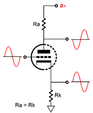
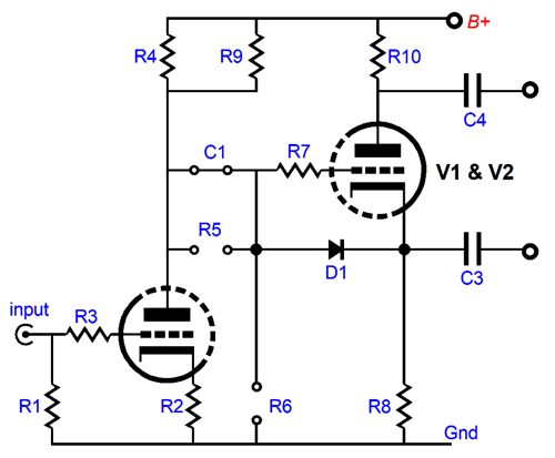
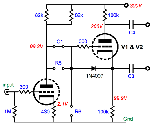
We still use the safety diode to prevent the phase splitter's grid from being exposed to the full B+ voltage while its cathode is a ground potential at start-up. With a B+ voltage of 300Vdc, the grounded-cathode amplifier's plate voltage of 100Vdc allows the phase splitter's triode to see almost 100V from cathode to plate. Note how the phase splitter's cathode and plate resistors and triode all see roughly the same voltage drop. At first sight, this might appear to offer the largest possible output voltage swing from the phase splitter, as it seems to imply two output swings of +/-100Vpk. It doesn't, as triode must see some voltage drop to draw current and we do not want the triode to enter positive grid voltages. In a line-stage amplifier, however, we are not seeking the maximum potential output swings. In a power amplifier, in contrast, we do. How do we get the biggest possible voltage swings from a split-load phase splitter?
The procedure is to find the maximum peak current of which the split-load phase splitter is capable with a given B+ voltage and plate and cathode resistor values and yet remain outside of positive grid voltages. We assume that the triode's grid has hit the same voltage as its cathode, i.e. 0V between the two elements: Ipk = B+/(2R + rp) Where R is the cathode and plate resistor value and rp is the triode's plate resistance. Next, set the idle current to half the peak current’s value: Iq = Ipk/2 = B+/(4R + 2rp) This amount of current flow against the cathode and plate resistor resistance gives us the voltage drop across these resistors. For example, if the B+ voltage is 400V and the plate resistance is 8k and the cathode and plate resistors are 16k in value, then the peak current flow is equal to 300V/(2x16k + 8k), which equals 10mA. And 0.01A/2 is equal to 5mA, which against 16k equals 80V. Thus, in this example, at idle the triode will see a voltage drop of 240V and the cathode and plate resistor will see an 80V drop. The peak output swing will come close to +/-80Vpk from each phase of output from the phase splitter. By the way, we can solve for the cathode and plate resistor value with the following formula: R = B+/4Iq - rp/2 Returning to the Balancer, here is an example setup with no internal coupling capacitor.
Okay, lets populate the circuit with part values and voltages.
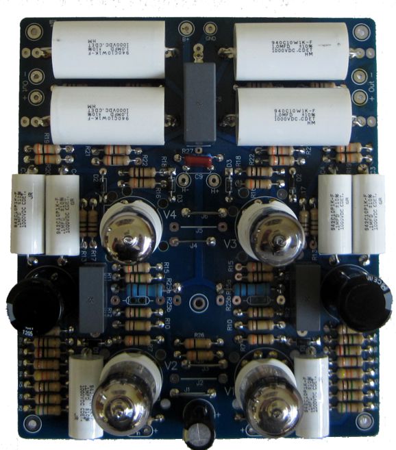
The 12AU7 input tube populates the grounded-cathode amplifier and split-load phase splitter positions. The ECC99 is a robust noval twin-triode tube that is similar to a 6N6 and 12BH7. I have found that the JJ ECC802 (the long-plate version of the 12AU7) and the JJ ECC99 make a fine sonic pairing—surprisingly so. About five years ago, I built a tube Aikido push-pull headphone amplifier based on this pair and optimized for a 300-ohm load. Just for giggles, I decided to try the headphone amplifier as a line-stage amplifier to drive 100k input impedance power amplifiers. Amazingly good, far better than I expected. Well, since then, I have used these two tubes in many projects. (Another good pairing is the 12AT7 and 6DJ8/ECCC88, they blend well together.)
Super Class-A with Unity-Gain Buffers
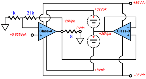
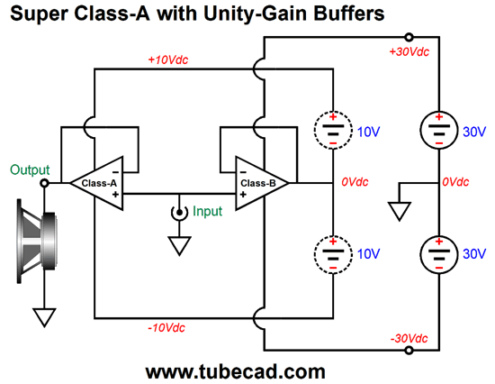
Do not fall into the confusion of thinking that the class-B amplifier is providing any signal gain to the class-A amplifier. It isn't. Instead, the class-B amplifier is only driving the floating power supply. In other words, as far as the class-A amplifier is concerned, the class-B amplifier does not exist. Or put differently, the class-B amplifier is part of the class-A amplifier's power supply. Well, we finally arrive where I wanted to start several post ago. What if we do not use any amplifiers in this arrangement, replacing the two with unity-gain power buffers, so no signal gain would be required? Thus, the class-A amplifier is replaced by a class-A buffer; the class-B amplifier, a class-B buffer. Okay, so where does the signal gain come from? If tubes are famous for anything it is for being able to swing big voltages. In other words, we purposely make a hot line-stage amplifier that can deliver peak voltage swings of 24V, which into an 8-ohm load will result in 36W of power. (Of course, we could include the hot tube gain stage within the Super Class-A amplifier. For example, an Aikido stage based on the 12AT7 would deliver all the gain we need.)
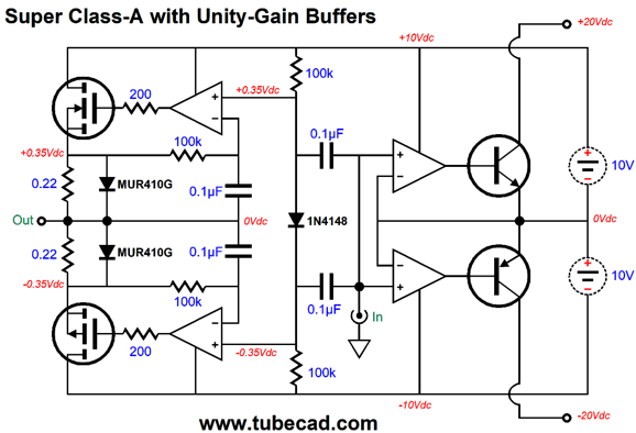
The class-B buffer runs off of the fixed +/-30V power-supply rails, while the class-A buffer runs off of the floating +/-10V rails. Now, in order for the class-A, push-pull buffer to remain in class-A, its idle current must be at least half of the peak output current swing. How do we find that amount? Simple: divide the peak voltage swing by the load impedance. In this example, 24V/8 equals 3A, so an idle current flow of at least 1.5A is needed by the push-pull unity-gain buffer. The class-B buffer, on the other hand, can let its output stage idle as near to zero amperes as we can get. But as we begin to drive the loudspeaker, the class-B buffer will experience all the current flow that the speaker sees. In other words, the peak current flow we expect with the class-B output stage to undergo is 3A. Let's now look at an extreme class-B buffer topology.
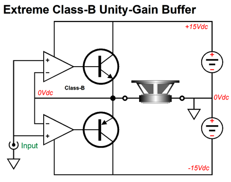
Two OpAmps are used to drive two output transistors. Almost no current flows through the output transistors at idle. As we would expect, the THD is poor, but with 100% negative feedback applied by both OpAmps, it is low enough for this application. (By the way, I have built this circuit before and it worked reasonably well. In contrast, this same circuit often encounters problems in SPICE simulations. The way SPICE works is that it is constantly looking at current flow—the movement of charge—from point to point. In the absence of current flow, the SPICE engine tends to lose its mind, which is why it secretly places a 1G-ohm load resistance between all nodes, so that some current can flow, albeit very little.)
Note how the class-B buffer's two OpAmps are powered by connecting to the floating +/-10V power-supply rails, while its two output transistors are powered by the fixed +/-30V rails. The class-B buffer makes the floating power supply move up and down like an elevator car. To see how this works, imagine the NPN transistor being fully turned on and the PNP transistor fully cut off; the floating power supply would still see the same 20-volt differential, but the top of the power supply would be near +40V, while its bottom would be near +20V. These two voltages will define the class-A buffer's power-supply rail voltages. As the class-A buffer follows the input signal, its power-supply rail voltage follow the same signal; thus, as far as the class-A buffer can tell it sees a constant +/-10V power supply. In fact, as far as it is concerned, its input and output voltages vary little from 0V. Since we used two OpAmps in the making of the class-B buffer, we could use two OpAmp to make the class-A buffer.
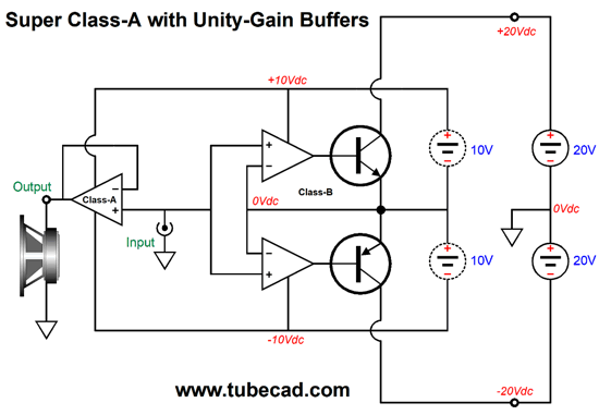
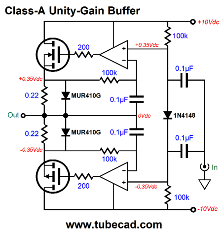
A 1N4148 signal diode is used as a voltage reference and the two 0.1µF coupling capacitors deliver the input signal with a DC offset to the two OpAmps. The OpAmps then use their considerable gain and 100% negative feedback arrangement to establish the two DC offsets across the two source resistors. If we do the math, i.e. 0.35V/0.22 ohms we get an idle current flow of 1.59A, which ensured a class-A window of operation of 3A of peak current output swing. The two MUR410G ultra-fast rectifiers are there to force a hard limit to the potential voltage drop across the 0.22-ohm source resistors. This important to prevent the 0.1µF from ever becoming overcharged, which would prompt the OpAmps to reduce the idle current below what is desired. (This is not a perfect setup, as the buffer will see music signals, not square-waves. Nonetheless, in practice, it works fairly well. One potential workaround is to place an additional diode across each 0.1µF capacitor.) Okay, let's add this class-A power buffer to the the class-B buffer and the two power supplies.
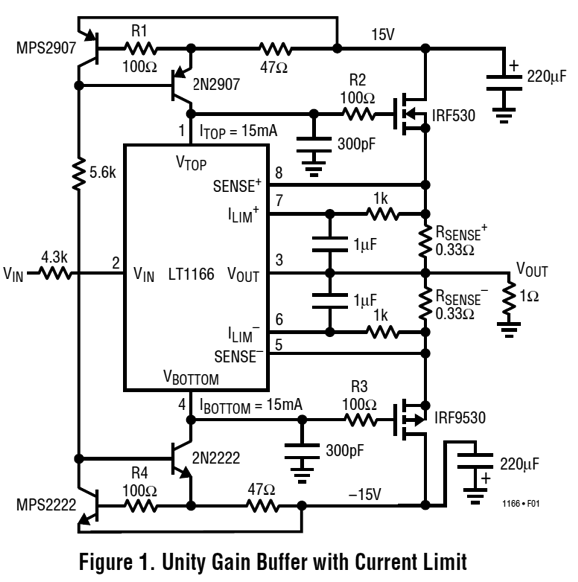
Of course, this is not the only way to go; it is only one possible way to implement Super Class-A power buffers. One possibility would be to use the LT1116 IC, which is an amazingly clever design.
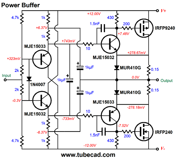
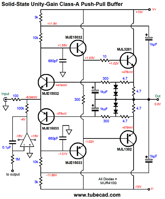
The LT1166 auto-biases the output MOSFETs by controlling the MOSFET's gate-to-source voltage. The IC offers an input pin, which interestingly enough is seldom used, even with the LT1166's data-sheet. Nonetheless, we can use two coupling capacitors to deliver the input signal to the two MOSFET gates. See post 211 for more details. On the other hand, if we want to do more work, we could use something like the following circuit, which is based on the famous diamond topology.
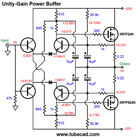
This power buffer idles 1.86A, which means that it can easily deliver 3Apk and still operate in class-A. If this buffer is kicked out of class-A by either encountering too large an input signal or by having to drive a lower than expect load impedance, then the MUR410G ultra-fast rectifiers will engage. Over the years, I have designed gobs of unity-gain power buffers. here is an example from post 352. (Just copy and paste the following "Unity-Gain Power Buffer site:tubecad.com" into your favorite search engine.)
This design idles at only 1A, so the source resistors should be replaced by 0.15-ohm types. In addition, the rail voltages are too high. Still, this is an interesting design, as it was designed to dissipate a constant power at idle, in spite of variations in wall voltage. Well, here is a new design:
Actually the schematic shown above was meant to drive low-impedance headphones, not speakers. But topology is topology. We could easily scale up in idle current and reduce the rail voltages.
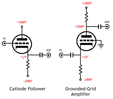
Cathode-Follower & Grounded-Cathode Cascade
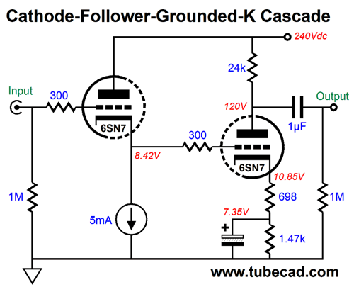
What if replace the grounded-grid amplifier with a grounded-cathode amplifier? Think of it as a cathode-grid coupled amplifier. But I prefer to call it a cathode follower & grounded-cathode cascade.
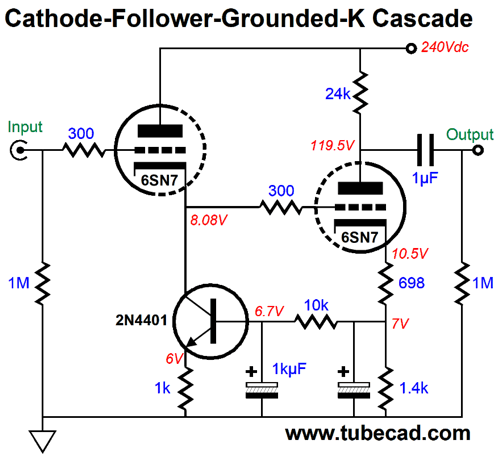
Much like its cousin, the cathode-coupled amplifier, this circuit offers an extremely low input capacitance. Is that important? Yes. Here is why: when we vary the volume control's potentiometer's position, we also vary the high-frequency cut-off frequency of a grounded-cathode amplifier, as the potentiometer presents a varying output impedance, depending on its position. The worst-case scenario is at -6dB, as that is when the output impedance will equal one fourth of the the total potentiometer resistance. For example, with a 100k potentiometer, 25k is the -6dB output impedance, which against the grounded-cathode amplifier's MIller-effect capacitance will prompt a drooping high frequency response. Unlike the cathode-coupled amplifier, this circuit inverts the input signal's phase at its output. In addition, if we carefully choose the part values, this circuit delivers vastly better PSRR than the cathode-coupled amplifier. The secret is to juggle the two cathode resistor values until the deepest power-supply noise null obtains at the output. The constant-current source could be a FET with a source resistor or an LM334 IC, but we could also roll our own CCS, as shown below.
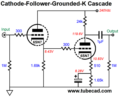
The 2N4401 NPN transistor is used to create a constant-current source (CCS). The 1.4k cathode resistor could be replaced by a 7V zener or voltage reference IC. Of course, many are troubled by any solid-state device in their stereo systems. (How is that entirely tube-based DAC going, by the way?) Thus, we could replace the CCS with a 1.69k resistor (or two 1.4k carbon-film capacitors in parallel.)
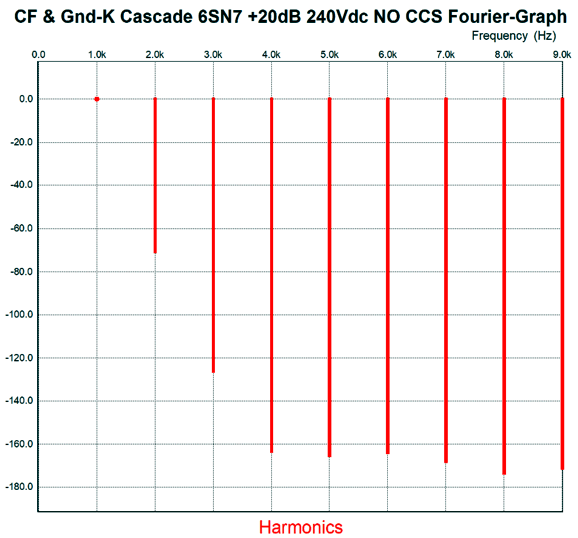
I had to jiggle the part values to get the best PSRR figure. Since this last version is the lowest-tech version, its distortion should prove the worst of the three designs. Here is the SPICE-generated Fourier graph for 1Vpk at 1kHz.
Far below 0.1% THD. Note the wonderful single-end cascade of harmonics. What I love about the circuit shown above is that it could have been created and built 80 years ago. If only I had a time machine. Consider this just part one of a two-part series on this circuit.
Music Recommendation: Katie Melua's Ultimate Collection (When she sang, there are nine million bicycles in Beijing That's a fact; It's a thing we can't deny," my mind immediately wondered if that was true; and if so, how could anyone know? This explains why I cannot watch TV.) Had her family moved to Nashville, rather than Belfast, I imagine that she would be a huge country-western singer today. Her lovely voice suits any genre that deals with storytelling and emotion. On her Ultimate Collection album, many delightful songs are arrayed. Her cover of Bridge Over Troubled Water was particularly interesting. What about her cover of Diamonds Are Forever? She starts out beautifully, but never kicks into overdrive, so while silky sweet the song lacks the needed oomph that Shirley Bassey delivered. //JRB
User Guides for GlassWare Software
For those of you who still have old computers running Windows XP (32-bit) or any other Windows 32-bit OS, I have setup the download availability of my old old standards: Tube CAD, SE Amp CAD, and Audio Gadgets. The downloads are at the GlassWare-Yahoo store and the price is only $9.95 for each program. http://glass-ware.stores.yahoo.net/adsoffromgla.html So many have asked that I had to do it. WARNING: THESE THREE PROGRAMS WILL NOT RUN UNDER VISTA 64-Bit or WINDOWS 7 & 8 or any other 64-bit OS. I do plan on remaking all of these programs into 64-bit versions, but it will be a huge ordeal, as programming requires vast chunks of noise-free time, something very rare with children running about. Ideally, I would love to come out with versions that run on iPads and Android-OS tablets.
//JRB
|
|
John Gives
Special Thanks to the Special 73
I am truly stunned and appreciative of their support. In addition I want to thank
All of your support makes a big difference. I would love to arrive at the point where creating my posts was my top priority of the day, not something that I have to steal time from other obligations to do. The more support I get, the higher up these posts move up in deserving attention. Only those who have produced a technical white paper or written an article on electronics know just how much time and effort is required to produce one of my posts, as novel circuits must be created, SPICE simulations must be run, schematics must be drawn, and thousands of words must be written. If you have been reading my posts, you know that my lifetime goal is reaching post 1,000. I have 548 more to go. My second goal is to gather 1,000 patrons. I have 927 patrons to go. Help me get there.
Only $12.95 TCJ My-Stock DB
Version 2 Improvements *User definable Download for www.glass-ware.com |
||


| www.tubecad.com Copyright © 1999-2019 GlassWare All Rights Reserved |