| John Broskie's Guide to Tube Circuit Analysis & Design |
06 June 2018 Post Number 427
SRPP Background
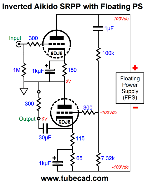
Fully 95% might be explained, however, by its massive simplicity: a few resistors and two triodes and one coupling capacitor. Of course, many of my variations the SRPP topology depart from the straightforward, if not Puritan, simplicity of the plain-Jane SRPP. For example, my inverted Aikido SRPP from post 329.
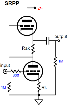
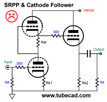
One characteristic that all my SRPP variations share, however, is the acknowledgement that the SRPP is fundamentally a push-pull power amplifier, not a single-ended gain stage. Many do not make this acknowledgement, so we end up with silly circuits, such as the following design.
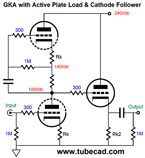
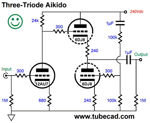
Three triodes are used, but not much results. Other arrangements of three triodes yield better results. For example, the following design realizes more gain and less distortion and improved PSRR.
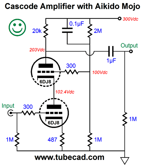
The top triode functions as an active load for the bottom triode and its two cathode resistors magnified by the top triode's mu, making the load impedance effectively much larger. For example, in the example above, the bottom triode might see a plate load greater than 200kohms, in spite of a 5mA idle current, with a resulting gain that approaches the bottom triode's amplification factor. In addition, the PSRR went from the SRPP's weak -6dB to something much healthy. If even more gain and an even better PSRR are desired, but with a tad more distortion, then we can bypass the input triode's cathode resistor with a large-valued capacitor. The cascading into a cathode follower is a good design move as it input impedance is nearly infinite, so input stages isn't dragged down; and the cathode follower's output impedance is low. If even more gain is required, the following cascode (which would then cascade into a cathode follower) is one possible answer.
Note where the 0.1µF capacitor terminates; B+ voltage, not ground. (See post 351 for more details on cascode PSRR enhancement.) The cathode follower, once again, does its job. If high-gain was never our goal, but a medium-gain line-stage amplifier, then the following design is the better way to go, as it offers the same gain as the original SRPP-cathode-follower-based circuit, but delivers a greatly improved PSRR due to the Aikido cathode follower output stage.
The moral here is that, much like the gratuitous sex and violence in a movie, gratuitous inclusion of an SRPP circuit betrays a want of taste and subtly of mind. On the other hand, if we need to deliver some power into a fairly low impedance load, the inclusion of the SRPP is justified.
Super SRPP
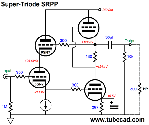
Note that the bottom 6SN7 gets the super treatment from the SRPP output stage, not the other way around. No,what I have in mind now is creating an SRPP circuit that behaves super. Well, the conversion was easier than I thought it would be. In fact, I came up with two variations: one with two NPN transistors and one with both PNP and NPN transistors.
The resistors mark R share the same value and set the idle current limit of the triodes, as these will see a voltage drop equal to transistor's emitter-to-base voltage, between 0.6V to 0.7V. Resistor Rk sets the desired cathode-to-plate voltage for the bottom triode by altering the idle current flow through the companion transistor. The higher in value this resistor is, the higher the resulting plate voltage must be to establish the idle current needed to turn on the bottom NPN transistor and the less the current flow through the bottom transistor. Resistor Rak is the current-sense resistor and it establishes the balance between top and bottom triodes for a specified load impedance. The key word in that sentence was "specified." The SRPP, even a super-triode SRPP, is load dependant and must be optimized for each load impedance. This is the price we must pay for not providing a proper phase splitter and relying on series regulated or reflexive phase splitting on the cheap. The 0.1µF coupling capacitor is required to evenly divide the B+ voltage between the triodes, as resistor Rak may not establish the right grid-bias voltage for the top triode. The output coupling capacitor must be large enough in value to allow low-frequency bandwidth down to 20Hz. The formula is simple: Where the capacitor value is in micro farads. We could use two PNP transistors or we could use two NPN transistors. The following variation uses two NPN types.
The same number of resistors is used, but the resistors are differently arranged. Let's flesh out this design in the following design example.
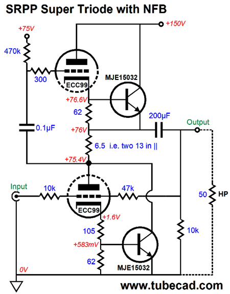
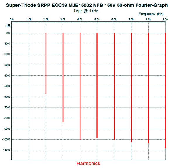
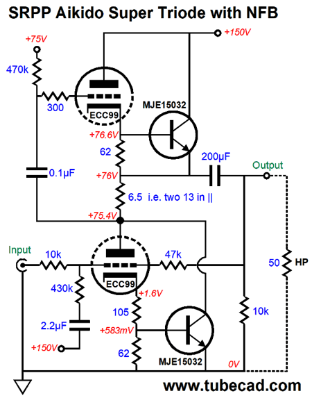
The intended load impedance is 50 ohms and the total idle current flow is just a tad less than 100mA. The current-sense resistor's value is an astonishingly low 6.5 ohms. Yes, I know that they do not make resistors in this value, but they do make 13-ohm resistors, two of which could be placed in parallel, yielding 6.5 ohms. The MJE15032 is 250V NPN transistor in a 40W TO-220 package. This transistor gets a lot of use in the driver stage of solid-state power amplifiers. In this design example, each transistor dissipates 6.75W. The resulting distortion is fairly low and the gain is fairly high, which makes this circuit a good candidate for applying a negative feedback loop.
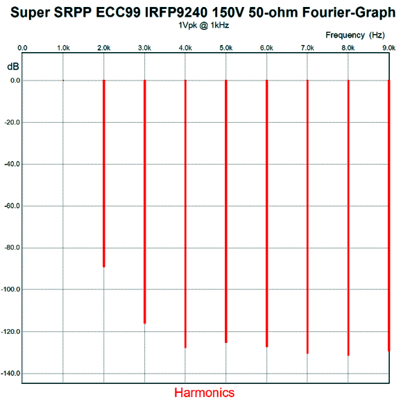
The 10k and 47k resistors limit the gain to about 3 and result in the following SPICE-generated Fourier graph.
With 1Vpk at 1kHz into a 50-ohm load, the THD comes in at a tad over 0.1%. The PSRR is -26dB, which is good for a tube circuit, but not great. Getting to great requires adding to extra parts: a 2.2µF capacitor and a 430k resistor, which terminates into the B+ voltage.
This addition allows a small portion of the power-supply noise to enter the negative feedback loop and provoke a power-supply-noise null at the output. (The value of the added resistor assumes that a low output impedance signal source is used, such as a CD player or DAC or MP3 player or high-quality line-stage amplifier; a 10k volume potentiometer does not count.) I wondered just how close to true Super-Triode operation were the triodes in this circuit, so I used SPICE to reveal the relative current swings. I found that the triode current remained nearly constant, which meets one of the three design requirements for Super-Triode operation. Here is the full list:
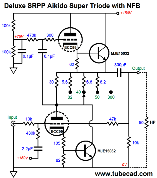
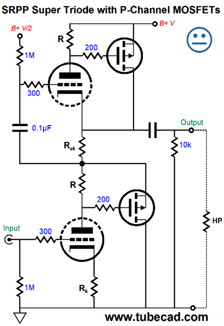
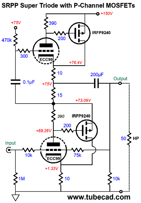
At one extreme, the load impedance is 300 ohms and the value of Rak is 30 ohms; at the other extreme, the intended load impedance is 32 ohms and Rak equals 30 in parallel with 5.6, or 4.72 ohms. We are not limited to transistors, however, as we could use two P-channel MOSFETs and, under some special circumstances, two N-channel MOSFETs. Lateral type N-channel MOSFETs require a much lower turn-on voltage, which works better with typical cathode-bias voltages, say between 1V to 3V. In contrast, the far cheaper and vastly more readily available HEXFET N-channel MOSFETs require a larger source-to-gate turn-on voltage, say between 3V to 5V. We can achieve such a cathode voltage, but usually only by increasing the cathode-to-plate voltage, which we don't want to do. Why not? Heat. Tubes don't mind heat, but solid-state devices do. And since the solid-state device will draw most of the current, it will dissipate most of the heat. Ideally, we should strive to limit the solid-state device's dissipation to no more than 10W, as that amount will allow us to use a 2.5in heatsink with a thermal resistance of 2.6°C/W with each solid-state device. The workaround is to use two P-channel MOSFETs.
We have no problem with developing a 4V voltage drop across the plate resistor. We do, however, encounter a problem with biasing the bottom triode, which is why there is no happy face. In SPICE simulations, I found that varying resistor Rk's value resulted in huge current flow changes. This is not good, as the MOSFETs might either turn off or melt down. The workaround resulted in the following change.
Note where the MOSFET sources terminate. The result is a further linearizing of the MOSFETs, but a diminution of total transconductance, which helps explain why the current-sense resistor, Rak, is now a big 15 ohms in value. More importantly, the cathode resistor value is no longer a hair-trigger mess. In the schematic above the triode draws 10mA, while the MOSFETs draw 120mA. In SPICE simulations, the results were impressive.
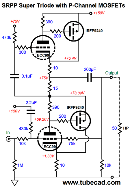
I strove to make this an apples against apples battle, so the gain equals the transistor-based version. The only thing missing is some Aikido mojo to enhance the PSRR.
Interestingly enough, the same 430k resistor to the B+ rail did the trick.
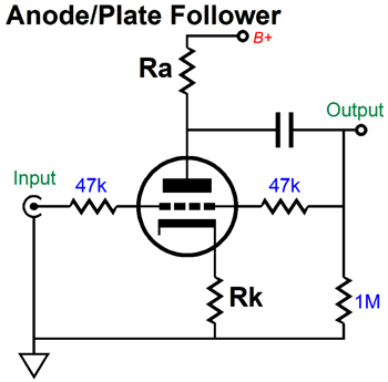
All-Tube, Horizontal SRPP-Based Headphone Amplifier
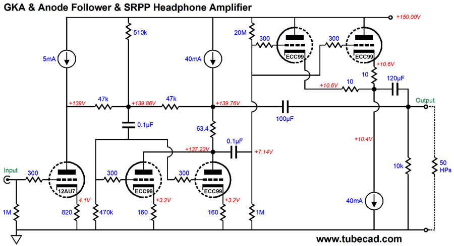
The SRPP portion is laid out in a horizontal fashion. Why? One reason: because I can. A second reason, a far important reason, is that the horizontal arrangement allows us to get away with a much lower B+ voltage. Is that important? In a headphone amplifier, indeed it is, as we will need a huge coupling capacitor to couple to the headphone's low impedance, say 200µF. Polypropylene capacitors can be bought in 100µF values, but that is about the limit; and they are huge. In addition, they are only rated for 250Vdc, which should not be used with a B+ voltage of 300V. On the other hand, with a B+ voltage of only 150Vdc, we have much less to worry about. Moreover, the B+ voltage reservoir capacitor should easily exceed the coupling capacitor's value; the 150Vdc B+ voltage makes this much easier to achieve. Fortunately, high-valued non-polarized electrolytic capacitors are made for loudspeaker use. But the voltage limit for these capacitor seems to end at 100V. In the horizontal arrangement, however, these capacitors could be used in the 100µF and 120F positions.
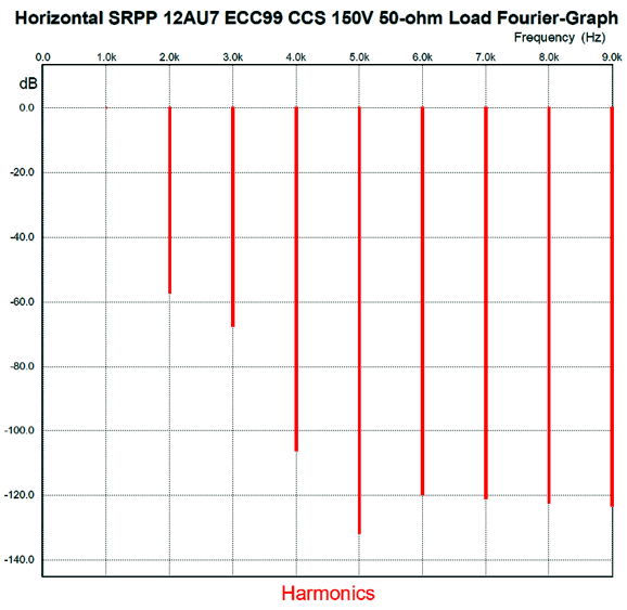
The SRRP stage is configured as an anode follower and uses a negative-feedback loop to lower its output impedance and distortion. The 510k resistor adds some Aikido mojo and greatly improves the PSRR, which is critical in a headphone amplifier. The 5mA constant-current source loads the single 12AU7 triode and the two 40mA constant-current sources allow the horizontal layout of the SRPP output stage. Effectively, they are not in the circuit in AC terms, although they do provide a DC current to both the B+ voltage and to ground. Neither wastes to much power, as each only dissipates about 0.4 watts. (Note the low voltage drop across each.) The 63.4-ohm current-sense resistor optimizes the output stage for 50-ohm loads. The peak class-A output current swing is 80mA, which against the 50-ohm load equals 4Vpk of voltage swing. All in all, this is a fun and interesting headphone amplifier design. In SPICE simulation, the performance actually exceeded my expectations.
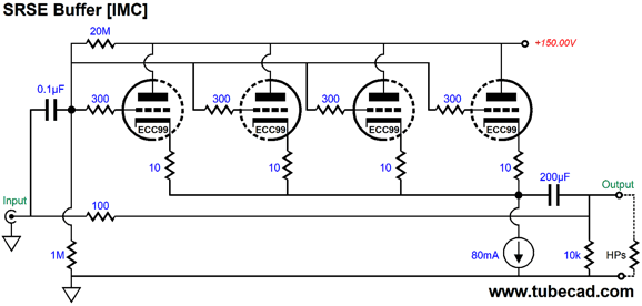
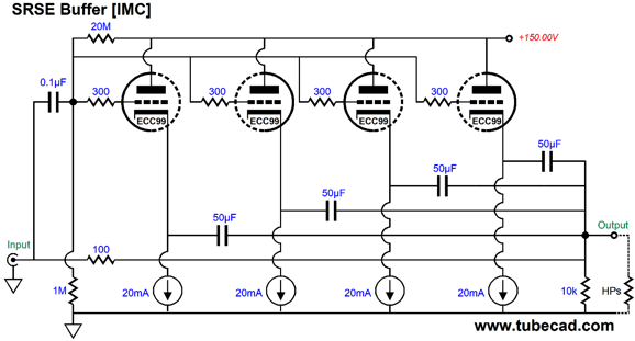
SRSE
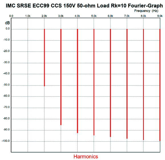
Four ECC99 triode and one 80mA constant-current source are used per channel. THe constant-current source only sees a 10V voltage drop at idle, so it does not get that hot. The ECC99 tubes, however, will get plenty hot. The 100-ohmm series resistor set an impedance multiplier ratio of almost 6:1, so the 50-ohm load appears as a 288-ohm load to the signal source. This circuit offers no gain; in fact, its gain is 0.67, which means that to get 1Vpk of output you must feed the circuit 1.5Vpk of input signal. Due to the 80mA constant-current source, the maximum symmetrical output is a tad over 4Vpk (the signal source will provide its own 13mA of peak current swing.) Here is the SPICE-generated Fourier graph of 1Vpk at 1kHz into 50 ohms.
Once again, not bad. We could give each triode its own constant-current source and coupling capacitor, which could 25V non-polarized electrolytic or a film capacitor.
With this setup, each triode biases to where its cathode needs to be to draw 20mA. The four 50µF capacitors combine to create 200µF.
Music Recommendation: Nadia Birkenstock
Tidal offers three of her albums and all are worth listening to. I would start with her album, The Glow Within, where she is accompanied by Steve Hubback on percussion, whose bells, drums, and gongs will delight your speakers, while her sweet voice (she sings in English) and tasteful harp playing will please your soul. Oh-oh, I find myself falling into a New-Age trance. For hard-core audiophiles, for whom sonics triumph over music, turn up the volume to window rattling level and try track 8, "L'Animal Sorcier," from her The Glow Within album. //JRB
If you enjoyed reading this post from me, then you might consider becoming one of my patrons at Patreon.com
User Guides for GlassWare Software
For those of you who still have old computers running Windows XP (32-bit) or any other Windows 32-bit OS, I have setup the download availability of my old old standards: Tube CAD, SE Amp CAD, and Audio Gadgets. The downloads are at the GlassWare-Yahoo store and the price is only $9.95 for each program. http://glass-ware.stores.yahoo.net/adsoffromgla.html So many have asked that I had to do it. WARNING: THESE THREE PROGRAMS WILL NOT RUN UNDER VISTA 64-Bit or WINDOWS 7 & 8 or any other 64-bit OS. I do plan on remaking all of these programs into 64-bit versions, but it will be a huge ordeal, as programming requires vast chunks of noise-free time, something very rare with children running about. Ideally, I would love to come out with versions that run on iPads and Android-OS tablets. //JRB |
John Gives
Special Thanks to the Special 67
I am truly stunned and appreciative of their support. In addition I want to thank
All of your support makes a big difference. I would love to arrive at the point where creating my posts was my top priority of the day, not something that I have to steal time from other obligations to do. The more support I get, the higher up these posts move up in deserving attention. Only those who have produced a technical white paper or written an article on electronics know just how much time and effort is required to produce one of my posts, as novel circuits must be created, SPICE simulations must be run, schematics must be drawn, and thousands of words must be written.
If you have been reading my posts, you know that my lifetime goal is reaching post number one thousand. I have 576 more to go. My second goal is to gather 1,000 patrons. I have 932 patrons to go. Help me get there.
Support the Tube CAD Journal & get an extremely powerful push-pull tube-amplifier simulator for TCJ Push-Pull Calculator
TCJ PPC Version 2 Improvements Rebuilt simulation engine *User definable
Download or CD ROM For more information, please visit our Web site : To purchase, please visit our Yahoo Store: |
|||


| www.tubecad.com Copyright © 1999-2018 GlassWare All Rights Reserved |