| John Broskie's Guide to Tube Circuit Analysis & Design |
| 13 July 2014
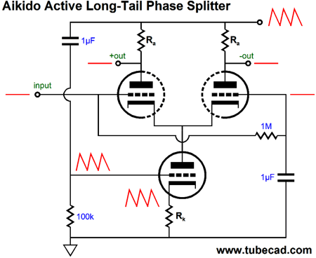
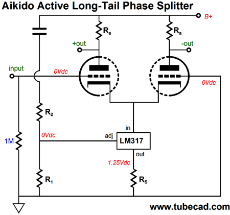
More Aikido Active-Tail Phase Splitters
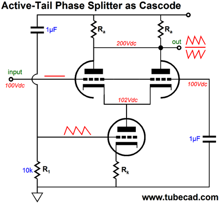
One way to understand how this feat of magic is accomplished is to view the circuit as being a cascode in disguise, with the top two triodes and two plate resistors being effectively in parallel. This cascode's input signal is the power-supply noise, which the cascode stage then amplifies and inverts at its output.
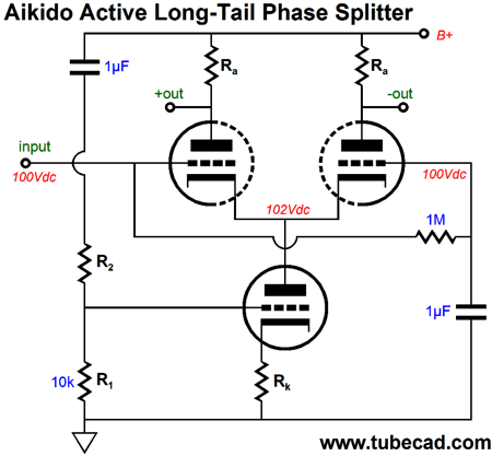
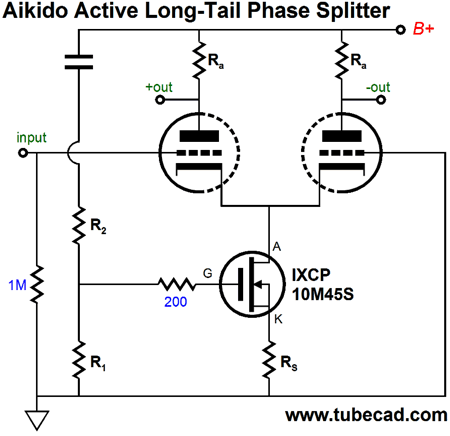
Well, the cascode circuit is known for two desirable attributes: high gain and low input capacitance. The first feature is a bit of a problem, as in reality the cathode resistor, Rk in the above schematic, will prove to be quite small in value, say only 300 ohms, but the plate resistors will be large in value, say 20k, which means gobs of gain obtains, far too much gain. The workaround is to throw away much of the input signal that the bottom triode sees, which the two-resistor AC voltage divider (R1 & R2) accomplishes in the following schematic.
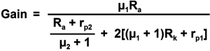
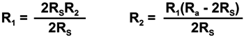
We can expect resistor R2 to be much larger than R1, as very little signal is required due to the high gain. How high is the gain? The formula is long, but not that difficult:
where µ1 and rp1 belong to the bottom triode and µ2 and rp2 belong to the top triodes. Once we know the gain, we can find the right voltage-divider ratio:
We can use other devices in place of the bottom triode, such as a pentode or MOSFET, but the easiest might be the LM317 positive, adjustable, voltage regulator. (The LM317-HV might be needed, as its 57V voltage rating; if an even higher voltage rating is needed, the TL783C is a good choice.)
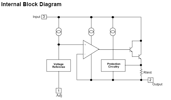
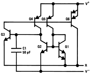
Assuming that resistor R1 is fairly low in value, the LM317 is easy to set up. Its output is 1.25V higher in voltage than its adjustment pin, so Iq = 1.25V/Rs For example, if we want an idle current of 10mA, we would divide 1.25 by 0.01 and get 125 as the answer. (The closest 1% resistor value is 124 ohms.) This setup would mean that each plate resistor sees a 5mA current flow. Internal to the LM317 is the following circuit.
The same PSRR-enhancement principles applies to the the LM317 as to the all-triode design.
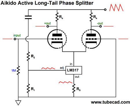
Because the LM317 functions a much closer approximation to a unity-gain amplifier, the math behind this topology is simple.
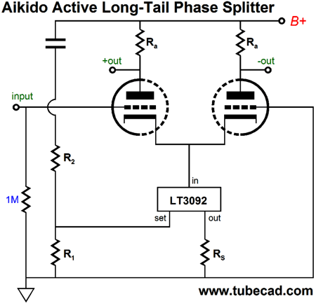
The first step is to find resistor Rs and then either arbitrarily specify a value for resistor R1 or R2, with R1 equal to 1k being best. For example, if R1 is 1k and Rs is 125 ohms in value and the plate resistors (Ra) are 20k in value, then R2 should equal 79k. (The closest 1% resistor is 78.7k, but then the closest 1% resistor to 125 ohms is 124 ohms.) Another device that can take the place of the bottom triode is the relatively new constant-current source (CCS) from Linear Technology, the LT3092. If you haven't heard of it, it is probably due to it's only being available in surface-mount packages. For shame, Linear Technology, for shame.
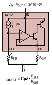
This new comer offers some good features:
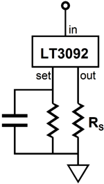
The brilliant design move was to forgo the internal voltage reference, replacing it with a precision constant-current source of only 10µA, which equals 0.00001A. This current flow into an external "set" resistor creates the voltage reference for the LT3092 CCS. This allows us to bypass the set resistor with a capacitor, thereby greatly lowering the noise from the CCS.
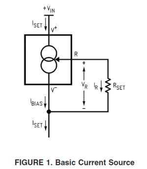
Of course, we are not doing that here; instead, we are using the "set" pin to inject a small portion of the power-supply noise. In contrast, the LM334 CCS cannot pull off this trick, as its internal voltage reference is not exposed. But then, the LM334 only requires one external resistor.
Internally, the LM334 holds the following circuit.
Like the LM317, the LT3092 uses the same formulas to set the correct voltage-divider resistor values.
The first step is to pick a value for the set resistor, R1, say 20k; then, find the right value for resistor Rs by using the following formula: Rs = 0.00001 x R1/Iq For example, with R1 equal to 20k and a desired idle current of 10mA, resistor Rs would equal 20 ohms. Yet another solid-state device that could take the bottom triode's place is the IXYS IXCP 10M45S CCS, which I am sure is just a depletion-mode MOSFET, not an IC constant-current source made up of many active devices.
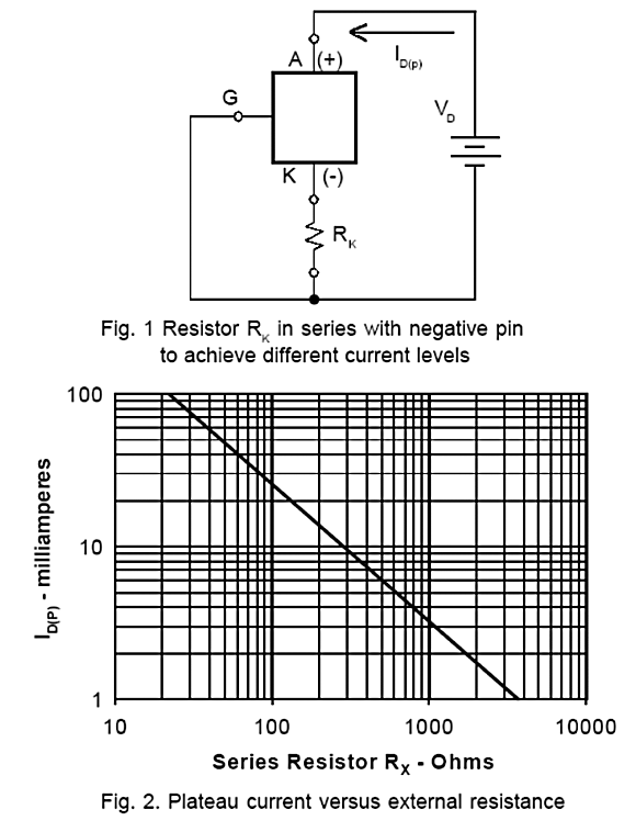
As the 10M45S offers so much more transconductance than any triode, we can probably get away with the preceding formulas for setting the voltage-divider resistor values. But first, we must find the right value for resistor Rs.
From the above graph, we see that a 294 (or 300) ohm Rs resistor is needed for an Iq of 10mA. Who knows, it might just work. My guess is that some Rs value fiddling will be needed, so find the Rs value first through actual experimentation, then apply the formulas.
Next Time
For those of you who still have old computers running Windows XP (32-bit) or any other Windows 32-bit OS, I have setup the download availability of my old old standards: Tube CAD, SE Amp CAD, and Audio Gadgets. The downloads are at the GlassWare-Yahoo store and the price is only $9.95 for each program. http://glass-ware.stores.yahoo.net/adsoffromgla.html So many have asked that I had to do it. WARNING: THESE THREE PROGRAMS WILL NOT RUN UNDER VISTA 64-Bit or WINDOWS 7 & 8 or any other 64-bit OS. I do plan on remaking all of these programs into 64-bit versions, but it will be a huge ordeal, as programming requires vast chunks of noise-free time, something very rare with children running about. Ideally, I would love to come out with versions that run on iPads and Android-OS tablets.
//JRB |
I know that some readers wish to avoid Patreon, so here is a PayPal button instead. Thanks. John Broskie
Kit User Guide PDFs
E-mail from GlassWare Customers
High-quality, double-sided, extra thick, 2-oz traces, plated-through holes, dual sets of resistor pads and pads for two coupling capacitors. Stereo and mono, octal and 9-pin printed circuit boards available.  Aikido PCBs for as little as $24 http://glass-ware.stores.yahoo.net/
Support the Tube CAD Journal & get an extremely powerful push-pull tube-amplifier simulator for TCJ Push-Pull Calculator
TCJ PPC Version 2 Improvements Rebuilt simulation engine *User definable
Download or CD ROM For more information, please visit our Web site : To purchase, please visit our Yahoo Store: |
|||


| www.tubecad.com Copyright © 1999-2014 GlassWare All Rights Reserved |