| John Broskie's Guide to Tube Circuit Analysis & Design |
28 March 2010
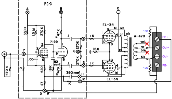
The Ultimate Dynaco ST-70 Mod: Remote-Sensing Feedback Almost twenty years ago, I had picked a fairly nice ST-70 from a garage sale but the amplifier's output terminal blocks were corroded and cheap looking. So, I replaced them with new, beautiful, industrial-grade, black-plastic, four-screw terminal strips, with tall fins between each screw segment to prevent shorts.
While attaching the output transformer's secondary leads to the terminal block, I realized that I had never owned a 16-ohm loudspeaker and that I didn't plan on using 4-ohm speakers. This immediately led to my asking myself what to do with four terminal connections and then to my wanting to implement a remote-sensing negative feedback setup on the Dynaco. The first step was to tape off the 4-ohm and 16-ohm leads. Next, was to add two 100-ohm safety resistors and attach the transformer's ground and 8-ohm leads. Five minutes later, I was listening to remote-sensing negative feedback. The Dynaco ST-70's signal source was of course unbalanced, as was the amplifier's input stage. The amplifier worked with either remote-sensing negative feedback or without it, using only two speaker cables. (If something other than an 8-ohm loudspeaker had been the intended load, then a different tap on the output transformer's secondary could have been soldered to the "Out+" connecter.)
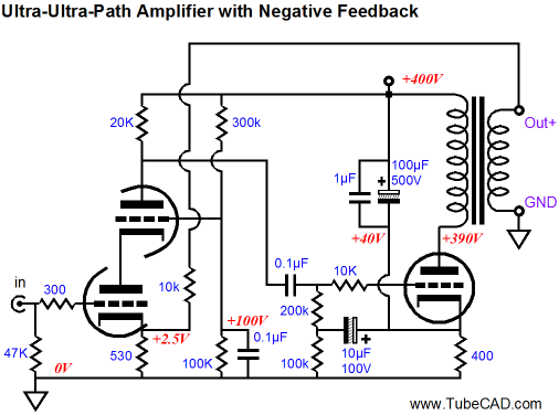
An amazingly simple modification this was. Most importantly, it sounded much better than the stock unit and only required four extra resistors and four-lead speaker cable. Do not think, however, that the amplifier's push-pull output stage is in any way necessary, as a simple regulated series voltage regulator that makes use of remote-sensing feedback is as about single-ended a circuit as can be imagined, being something akin to half of a class-B amplifier. Neither push-pull nor transformer coupling is required. In fact, the technique can be used with single-ended amplifiers, such as the one shown below.
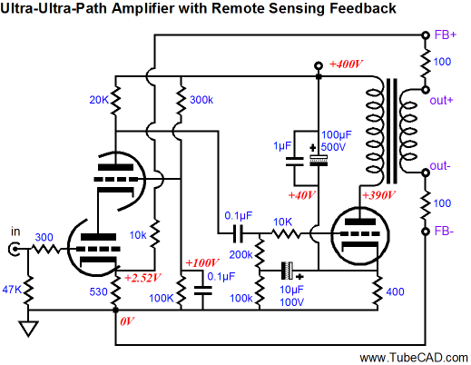
Ultra-Path Amplifier with Remote-Sensing Feedback Such an arrangement would spell trouble with a conventional single-ended amplifier that bypassed its output tube's cathode resistor with a capacitor that terminated into ground. But in this ultra-path output stage, the output tube's cathode is effectively "grounded" at the B+ rail, not ground. Thus, the output tube's grid and cathode and plate all see the same amount of B+ noise, which means that the power-supply noise drops out of the equation. If the cascode stage were decoupled from the B+ rail via an RC filter for example, the power-supply noise would be "seen" by the output stage at the output tube's cathode and, as a result, amplified . Adding the 10k negative feedback resistor introduces some negative feedback to the input stage, which will lower the amplifier's output impedance and distortion, while extending its bandwidth but reducing its gain. Adding remote-sensing negative feedback is only slightly more complicated.
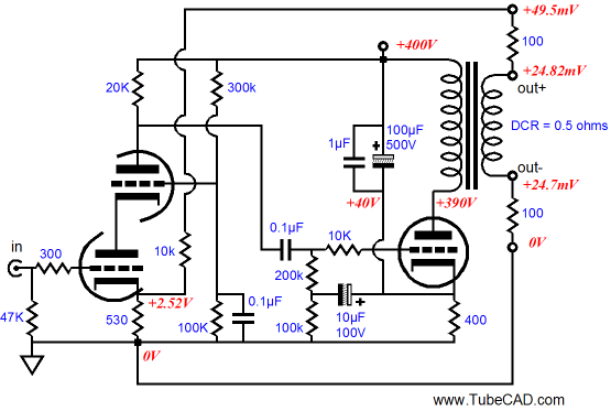
Note how the two safety 100-ohm resistors complete the negative feedback loop, even without the external loudspeaker load and sensing cables. Also note that the output transformer's secondary is not directly grounded. Note it again... and again... and again. Why the stressed emphasis on this point? Many solder slingers love to add ground wire after ground wire, causing huge hum problems along the way. In other words, there might be two or more ground wires connecting to the transformer's secondary and we do want to correct for the ills begot by the negative speaker cable lead as well as the positive lead. In addition, we want the amplifier's output and the loudspeaker load to behave as a balanced configuration as much as possible. I know some readers might be fretting over possible DC offsets saturating the output transformer's core or harming the loudspeakers. Have no fear, very little DC voltage appears at the amplifier's output, as the transformer's secondary's DCR is very low, say 0.5 ohms, which against the 10k feedback resistor results in a very small DC offset. One tenth of 1mV is not likely to harm any speaker or cause core saturation (remember it is the differential voltage across the output that counts).
Now, let's add the loudspeaker and the four-wire speaker cable:
Note how the 100-ohm safety resistors are effectively shorted out by the speaker cable's low DCR—well, we assume it's low, but some audiophiles like to run skinny wire, say 24 gauge, which presents 0.2567 ohms per ten feet. Thus, two 15-foot stretches of wire would represent a sizable amount of series resistance. Now, here is an example of how remote-sensing negative feedback can overcome the voltage loss across short cables, say half an inch of 24 gauge or a few feet of thicker wire.
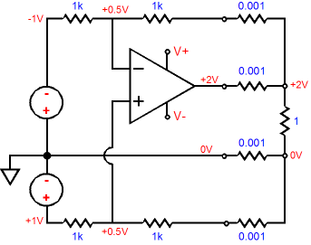
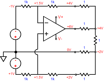
In the circuit above, we see two input signal sources, each of which presents a DC voltage of one volt. The amplifier is configured for unity-gain output, so the load sees 2V across its leads. Of course, with only 0.001 ohms of resistance per cable run, we didn't expect to lose much voltage due to the cabling. Note that power amplifier must deliver 2A of current into the 1-ohm load. Now, let's up the cable resistance to 1 ohm, say placing the load 39 feet away from the amplifier and using 24 gauge copper wire.
Amazingly, the load still sees 2V across its leads. The amplifier's two remote-sensing negative feedback loops undo the voltage loss across the cables, as they relay back to the amplifier what actually appears across the loudspeaker's input terminals. But this miracle came at a stiff cost: the amplifier must put out three times the output voltage to establish the required 2V across the load resistance (but with no increase in current delivery). By the way, do note that all four leads do not share the same current flow, as the remote-sensing negative feedback wires see only a few milliamperes of current flow, while the two primary speaker cables must conduct 2 amperes of current into the 1-ohm load; thus, the vastly dissimilar voltage drops across the wires. Of course, we are not likely to run speaker cables so thin and so long as to impose additional 16-ohms of series resistance with the 8-ohm loudspeaker. And to be honest, my goal never was to preserve a fixed power delivery into the loudspeaker; instead, my goal was to undo whatever squirreliness the speaker cable might add to the mix by including the speaker cables within the feedback loop.
Added Zo Trick
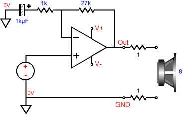
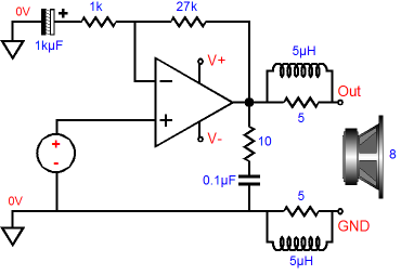
It troubled me that his resistor fix worked as well as it did, as I was not convinced that his explanation was adequate. Most multi-driver speakers include resistor L-pads for the midrange and tweeter; these impose an increased source Zo as well as attenuation and I never thought that they improved the sound quality; indeed, just the contrary. My guess was that his added resistors were doing something more, that they not only added series resistance, they decoupled the speaker cable and loudspeaker crossover from the amplifier's feedback loop. In other words, my guess was that the amplifier was simply much happier not having to deal directly with naked inductance and capacitance. This line of thinking led me to try making a subtle change to the typical solid-state power amplifier output stage. First, let's look at the way it is usually done. Below, we see a solid-state power amplifier with a Zobel network consisting of a 10-ohm resistor and 0.1µF capacitor shorting the amplifier output to ground.
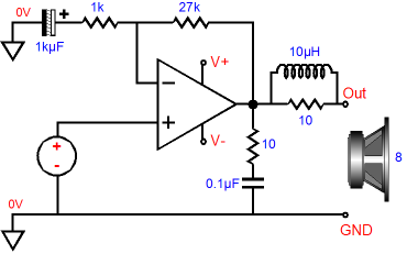
What is a Zobel network? A Zobel network, also known as a "Boucherot cell" and an "RC snubber," is essential to most solid-state power amplifier's stability, not so much because of crazy external reactive loads, but due to internal phase shifts within the amplifier. For example, if the Zobel circuit is removed, many solid-state amplifiers will oscillate with no external load. At the same time, a solid-state amplifier that might prove stable without both the Zobel and the external reactive load, can break into oscillation with a loudspeaker attached to its output. The second addition to the amplifier's output is the 2W 10-ohm resistor with several turns of magnet wire around its body. These damped inductors decouple the amplifier from RFI picked up by the speaker cable and crossover. Only one set is used—normally. This has always bothered me, as I feared that the ground connection to the speaker cable would become contaminated. After hearing my EE friend's resistor experiment, I made the following change to a solid-state power amplifier I owned.
The single 10-ohm resistor has been replaced with two 5-ohm resistors, each with half the wire coiling that the single resistor had received. So, how did it sound? I thought it sounded a tad better, but then, every mother's child (or amplifier hot-rodding technique) sounds glorious to her. Moreover, the planer loudspeakers I was driving at the time were fairly flat in terms of impedance, so maybe they didn't need much help to begin with. And this change certainly didn't come close to offering that "you have got to be kidding me; that's amazing quality" that the remote sensing feedback arrangement yielded. Now, here's a question: should each of the connections to remote-sensing feedback terminals on the back of the amplifier also hold damped inductors?
Probably, yes. More physical experimentation is required—at the very least, a thorough array of SPICE simulations is needed. Doing the latter, however, will require creating realistic SPICE models for the loudspeaker cable and a typical loudspeaker that holds a complex crossover; not easy. Before moving on to the next topic, I should mention that the Zobel network often needs to be duplicated at the loudspeaker terminals, as many loudspeakers exhibit a rising impedance at high frequencies due to driver's inductance. The typical Zobel set of 10-ohm resistor and 0.1µF capacitor, however, defines a high-pass RC filter that transitions at 159 kHz, which may prove far too high. (Something like 8 ohms and 0.68µF night be more appropriate.) By the way, these typical solid-state power amplifier Zobel values are not set in stone, but rather result of tradition and laziness. For example, the famous gain-clone power OpAmp, the LM3886, has a resistor value of 2.7 ohms specified in its data sheet from National Semiconductor; interestingly enough, the same value is specified in the TDA7294's data sheet. And the lowly LM675's data sheet specifies 1-ohm and 0.22µF for its Zobel.
Remote-Sensing Feedback on the Cheap:
I know readers will be troubled by the four connections required by remote-sensing feedback, as they will not see in value in adding the second remote-sensing connection to the loudspeaker's negative input terminal. In other words, why can't we just use three wires, two for delivering the power into the loudspeaker and one for remote negative feedback sampling?
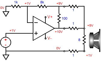
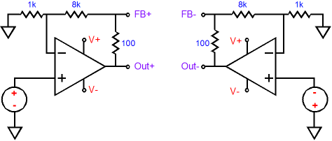
That such a question could even be contemplated is a powerful testament to unshakeable faith many have in the metaphysical category of Ground, Ground with a capital "G" and set in the same typeface as the "S" that adorns Superman's chest; an all-strong, all-forceful, all-compelling, almighty, all-potent, all-powerful Ground that is the electrical equivalent to gravitational black hole and from which no electrical signal can escape. Thus, the faulty logic goes like this, since the loudspeaker's negative input terminal attaches to the amplifier's ground, nothing can ever go wrong at this point. How could it? It's ground after all! If only that were true, life would be so much easier. Here is an example of how three wires are not enough.
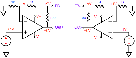
The above amplifier is configured as a DC amplifier with a gain equal to (1k + 8k)/1k (in other words, 9). One volt is presented to its input and, amazingly enough, 9V appears at the loudspeaker positive terminal, in spite of loudspeaker cable 1-ohm resistance per length. So, a single wire remote-sensing negative feedback setup can work, right? Wrong. The +9V at the speaker's positive terminal is certainly welcome, but the +1V at its negative terminal is not. The total differential voltage across the speaker's terminals is only 8V, not the desired 9V. We can be generous and say that the single-wire approach is 89 percent as good as the two-wire remote sensing approach, as 8/9 equals 89%; or, looking at it from the negative terminal, should we say that 1V/0V equals infinitely stinky?
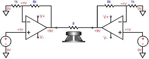
Balanced Remote-Sensing Negative Feedback
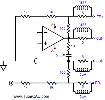
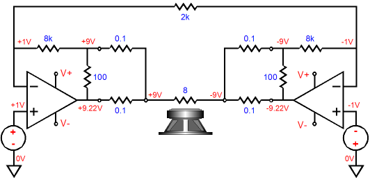
Each power amplifier shares a common power supply with the other and the two swing a differential output voltage equal to 18 times the peak input signal voltage. Such amplifier can develop huge power outputs with seemingly low-voltage power supply rails, as a doubling of voltage across the load equals a quadrupling of power into the load. Do not look for any free lunch here; there isn't any. The wattage is increased fourfold because the voltage and the current are both doubled. In other words, as far as each individual power amplifier is concerned, it is driving a 4-ohm load, so it delivers twice the current. If a true 4-ohm loudspeaker is attached, each individual power amplifier will effectively see a brutal 2-ohm load, which can easily trip its output-stage-protection circuitry. Okay, do not get me wrong here; I do like this topology—a great deal in fact. I like the way it eliminates connecting the loudspeaker to any magical grounds; I like the way it effectively doubles each individual power amplifier's slew rate; and I like the relatively low power supply rail voltages. I just do not want to create any false hopes—that being the job of slick ads in high-end-audio magazines. Here is a trick question, How many wires would be needed to convert the balanced power amplifier into a remote-sensing negative feedback amplifier? Eight? Eight seems to make sense, as twice the output stages should imply twice the wires. Amazingly enough, just four wires are needed, the same number as the plain unbalanced power amplifier.
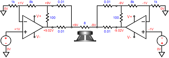
And with load and cables:
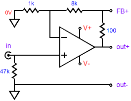
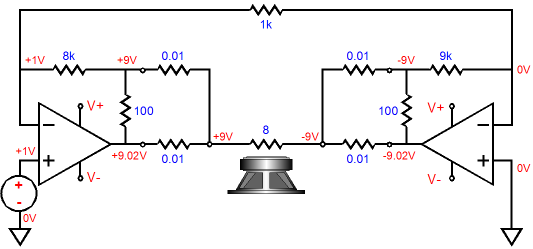
Wait a minute; doesn't this look a lot like the single-wire approach that we dismissed earlier? Similar, but not the same, as we never rely on magical ground connections. Each loudspeaker terminal gets its own feedback path back to the power amplifier. (In fact, we could use a mono-polar power supply and reference each individual power amplifier's output to half the B+ voltage, so both output stage outputs would not even be at ground potential.) So, what's not to like about this arrangement? Well, for many, the need for a balanced input signal source is a huge liability. But need it be? An input transformer could easily split the phase of an unbalanced input signal; and in the process, break a possible ground-loop. In addition, the following similar circuit accepts an unbalanced input signal.
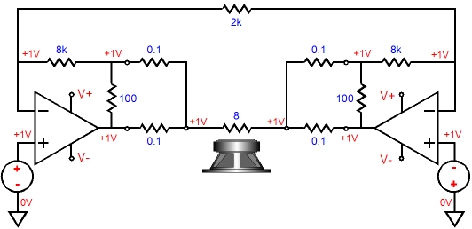
Before you start scratching your head, compare the values of the negative feedback resistors used by each individual power amplifier, 8k and 9k. These dissimilar resistors yield a gain of 9 for the amplifier on the left and 9 for the amplifier on the right. How is that possible? The amplifier on the left is a non-inverting amplifier, while the amplifier on the right is an inverting amplifier. The gain for the amplifier on the left is set by (1k + 8k)/1k, while on the right, by 9k/1k. We can even use this topology with a balanced input signal, as shown below.
Note the higher-resistance speaker cable from the previous example. And note the symmetry in part values between both individual power amplifiers. (Also note the 2k resistor that serves the as the common gain-setting for both amplifier; it is effectively two 1k resistors in series.) Since we have already covered a balanced-input version, does this version offer any advantages over the first topology? I believe that it does. Both versions offer a wonderful CCMR, but this last version is more tolerant of common-mode signals in one important way. Here is an example. Let's say that both balanced input signals carry an unfortunate 1V DC offset. The following amplifier will amplify the 1Vdc common-mode signal to 9Vdc at each output. The loudspeaker sees no net differential voltage, so it ignores common 9Vdc at each output; no difference, no effect. But the output stage will no longer be centered, which will lead to asymmetrical clipping, as positive-going signals will sooner run into the positive rail voltage.
In contrast, the following circuit only offers unity gain to common-mode signals, so the two output stages do not travel too far from ground potential. No doubt, there might be situations wherein the common-mode noise—either AC or DC noise—greatly exceeds the desired balanced input signal; and in these situations, the last version, as shown below, would shine.
Overtime
//JRB |
E-mail from GlassWare Customers
High-quality, double-sided, extra thick, 2-oz traces, plated-through holes, dual sets of resistor pads and pads for two coupling capacitors. Stereo and mono, octal and 9-pin printed circuit boards available.  Aikido PCBs for as little as $24 http://glass-ware.stores.yahoo.net/
Only $19.95
Download or CD ROM
To purchase , please visit our Yahoo Store:
|
|||


| www.tubecad.com Copyright © 1999-2010 GlassWare All Rights Reserved |