| John Broskie's Guide to Tube Circuit Analysis & Design |
| Post 198 23 January 2011
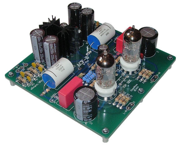
Aikido Cathode Follower Version 2 [ACF-2] Once again, after building and testing the ACF-2, I was surprised by how an active buffer could improve upon a passive line stage. I expected the slight loss of gain and the added circuitry to get in the way; instead, the imaging improved: instruments sharpened in focus and seperated from each other. Strange. Nor is this the first time I have encountered passive losing to active. Sometimes, more is more.
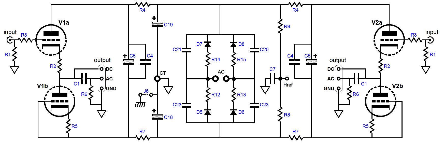
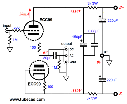
Both channels and the bipolar high-voltage power supply are shown in the above schematic. The ACF-2 uses a bipolar power supply and two triodes per channel to greatly improve the cathode follower's PSRR figure. In addition, the bipolar power supply allows us to DC couple the ACF's input and, possibly, to eliminate the need for an output coupling capacitor. If the power amplifier holds a coupling capacitor at its input or if the amplifier uses a tube at its input, then the ACF-2's output capacitor may not be needed. With DC-coupled, solid-state power amplifiers, on the other hand, any DC offset, even a few millivolts is too much and an output coupling capacitor is required. (I know that many like to tune their systems with coupling capacitors and the ACF-2 will serve that application quite well.)
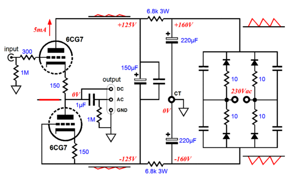
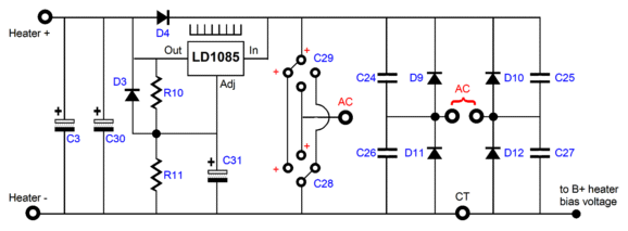
The ACF-2 circuit is quite simple. The top triode defines a cathode follower with a DC input and an active cathode load, which is made up from the bottom triode and its cathode resistor. These two triodes and their matching cathode resistors balance each other almost perfectly, nulling the power-supply noise from the ACF's output. To better help you understand why this should be so, imagine two identical resistors wired in series and spanning a bipolar power supply two voltage rails. Because both resistors are equal in value, the voltage division is one half. Thus if the two rail voltages differ only in polarity, the voltage at the resistors' common connection will be 0 volts. One half of +125V and -125V is 0V; in other words, the midpoint between +125Vdc and -125Vdc is 0V. The same math holds up to the presence of noise on the bipolar power supply rails, which means that as long as the rail noise is in anti-phase and their amplitudes match, the output noise from these rails will also equal zero at the voltage divider's midpoint. In other words, the ACF-2 greatly improves on the cathode follower's already fine PSRR. In addition, the ACF-2 produces a tad bit less distortion than comparable cathode follower by using the triode’s own nonlinearity against itself. The obvious tube choices are the 6CG7, 6DJ8, 12AU7, 12BH7, and ECC99. But many other tubes could be used. The only stipulations are that the two triodes within the envelope be the same and that the tube conform to the 9A or 9AJ base pin-out. The higher the mu, the closer to unity gain. The higher the transconductance, the lower the output impedance. Other possible choices are 6H30, which would deliver a low output impedance and high idle current that could drive long high-capacitance-laden cables; and the little-known 5963 & 5965, which were design for long life in computers. In other words, the list of possible tubes is a long one: 6AQ8, 6BC8, 6BK7, 6BQ7, 6BS8, 6DJ8, 6FQ7, 6GC7, 6H30, 6KN8, 6N1P, 12AT7, 12AU7, 12AV7, 12AX7, 12BH7, 12DJ8, 12FQ7, 5751, 5963, 5965, 6072, 6922, E188CC, ECC88, ECC99… Note, however, the 12B4 and 5687 cannot be used with this PCB. The ACF-2 PCB also holds the heater raw power supply and voltage regulator, the LD1085 low-dropout adjustable voltage regulator. The regulator can be set to an output voltage between 6V to 25V, but the assumption is that a 12Vdc output voltage will be used for the heaters, so that either 6.3V heater tubes (like the 6FQ7 and 6DJ8) or 12.6V tubes (like the 12AU7 or 12AX7) can be used. Both voltage types must be used exclusively; for example a 6GC7 in one channel and a 12BH7 in the other channel cannot be used at the same time. The ACF-2 holds three jumpers that can place the two heater elements in series or in parallel.
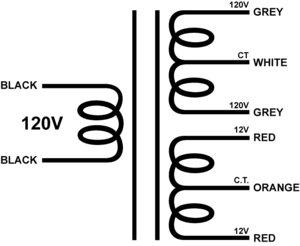
As can be seen, the power supply can accept a configuration as either a full-wave bridge rectifier circuit or a full-wave voltage doubler rectifier. Configured as a voltage doubler, which is a good choice when the secondary voltage is only 6.3Vac, capacitors C28 & C29 must be placed in series by being rotated 90 degrees clockwise, so the positive leads point to the center-tap pad at the bottom of the PCB; the secondary then attaches to single AC pad in between capacitors C28 and C29 and AC pad that feeds rectifier D9 and D11; and D10, D12, C25, C27 are left off the PCB. I always run 12Vdc, rather than 12.6Vdc, as the slightly lower voltage will extend the tube life and, somewhat paradoxically, increase the tube's linearity. Before anyone is tempted to write me asking which transformer to use with the ACF-2 (I just cannot take anymore e-mail), I would check out the following transformer from Edcor.
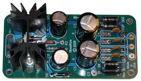
And yes indeed, the ACF-2 PCB can handle the 24Vac CT winding in the heater section. (The ACF-2 heater rectifiers can be configured in a full-wave center-tapped topology, so the 24Vac CT becomes effectively a 12Vac winding.) The Hammond P-T269AX is another possibility; its 6.3Vac winding can be used with the voltage doubler rectifier configuration and then regulated down to 12Vdc. The transformer's secondary maximum voltage limit is about 280Vac CT (140V-0V-140V), as the RC filter capacitor C5 presents a strict 400Vdc voltage limit. (Remember, when a tube is cold, it doesn't conduct, so the RC filter will not diminish the full bipolar power supply differential voltage.) The ACF-2 PCBs and kits are available now at the GlassWare-Yahoo store for an embarrassingly low price. Be sure to download the user guide PDF by clicking on the user guide image on the right.
Logitech Squeezebox™ Duet & Touch
I plan on building up a chassis that uses an ACF-2 with all its parts soldered to the bottom of the PCB, except the tube sockets, which will mount on the top of the PCB (the PCB holds bottom-side pads for the LD1085 regulator) and the tubes will protrude through two holes on the top of a long, but narrow chassis, say 7 by 13 by 3 inches. The Logitech Duet will sit on top behind the tubes and receive its power from a regulated 9Vdc power supply within the chassis. I plan on taking advantage of the 5Vac tube rectifier winding on many intended-for-tube-use, high-voltage power transformers to power the 9V regulator. How do you get 9Vdc out of a 5Vac winding?
I will use one of my H-PS-1 power supply boards in the voltage-doubler configuration, which will turn the 5Vac into about 12.8Vdc, which will supply the adjustable LDO regulator, which in turn will reduce the voltage to 9Vdc.
The chassis will present three short cables to the Logitech Duet, one power supply cord and two RCA jack-terminated cables for obtaining the audio signal from the Duet. The only controls on the chassis's front panel will be an on/off switch (the exposed tubes themselves will function as the indicator light). I might even glue the remote control stand tot he top of the chassis and feed its cable into the chassis, where it would terminate into a constantly powered 5Vdc power supply.
ACF-2 Headphone Driver?
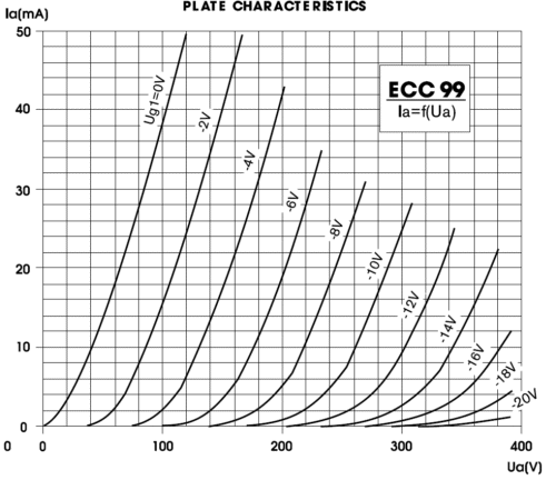
I would use the ECC99 from JJ, as it is an amazing little tube. From the plate curves, we see that with a cathode-to-plate voltage of 110V and -2V on its grid, the ECC99 draws 20mA, which implies a cathode resistor of 100 ohms. Now, 20mA against 300 ohms equals 6Vpk of voltage swing. Plenty loud. My only concern is the 200-ohm output impedance might prove too high, although I am sure that many would enjoy the fatter, more tube-like sound that the relatively high output impedance (Zo) would impart.
Although if you plan on driving the ACF-2 from an iPod or Zune, do not expect very loud playback, as these devices do not put out that much signal voltage.
Impedance Multiplier Circuits and the PS-6
Where to start and, more importantly, where to end? I have come up with dozens of suitable hybrid designs over the last two decades. One topology that immediately came to mind, however, wasn't one of my designs. A.J. van Doorn's article in May 2008 issue of audioXpress, "Build a Hybrid SE OTL Amp," presented a clever hybrid amplifier topology that directly coupled a high-power vacuum tube to a solid-state power amplifier's output. (I commented on Mr. van Doorn's design back in blog number 140.)
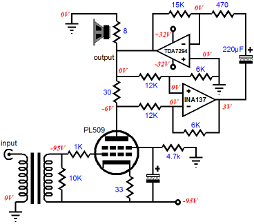
What I liked about his design was that the single tube added voltage amplification to the mix, whereas all the other hybrid designs I considered all belonged to the unity-gain hybrid buffer category. (Although building a high-gain tube-based line stage is easy enough, it's nice to have a portable power amplifier that you take over to friends houses; in other words, voltage gain is often essential.) Moreover, in his design, the tube's idle current, which flows into the solid-state amplifier's output stage, forced the solid-state amplifier to shut off its bottom output devices (PNP transistors or P-channel MOSFETs) at idle, displacing the crossover notch as a result. In other words, when the input signal swings far enough negatively, the solid-state power amplifier will have to switch on its bottom output devices and turn off its top output devices at some negative output voltage swing—we hope well outside the zero-crossing, where the ear is quite sensitive. (See blog entries 88 and 89 for more information on crossover displacement.) Mr. van Doorn's design requires a high-voltage negative power supply rail, which I certainly could establish with the PS-6 by inverting both the high-voltage rectifiers and capacitors, but ultimately I would prefer to deal with positive high-voltage rail and forgo the input transformer and the INA137 differential amplifier. But as I stared at his design, I saw that it could be viewed as being something of an impedance-multiplier circuit with a near-infinite impedance multiplication, a load impedance magnification roughly equal to the 30-ohm plate resistor divided by the solid-state amplifier's output impedance. Converting the circuit into a more recognizable impedance-multiplier circuit, on the other hand, would allow us to better use the tube's meager current swings and to eliminate the INA137 differential amplifier.
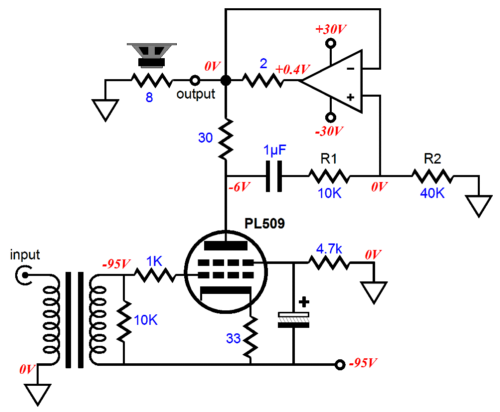
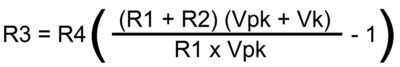
By adding the 2-ohm series resistor to the solid-state power amplifier's output (and enclosing it with the amplifier's feedback loop), we have created an impedance-multiplier circuit with an impedance multiplication of 16, as (30 + 2)/2 equals 16. The power amplifier has been reconfigured as a unity-gain power buffer to make the circuit's functioning easier to see, but this circuit will provide gain nonetheless. Assuming a peak positive voltage swing of 24Vpk into the load impedance (which we could not actually achieve in reality, as the power supply rail voltages would sag and the power amplifier's output stage incurs a few volts of loss that will prevent the amplifier from swinging up to +30Vpk at its output), the 2-ohm series resistor would see a 6-volt voltage drop, as 3A against 2 ohms equals 6V. In other words, at full power, the series resistor will dissipate 9W and the 8-ohm load, 36W. The 10k and 40 based two-resistor voltage divider at the power amplifier's non-inverting input, sets the appropriate amount of tracking by the solid-state power amplifier to ensure that the tube's entire current swing, from 0mA to 400mA overlaps the entire solid-state power amplifier current swing into the load. How were these two resistor values found? The formula is a simple one: R1 = R2[(Vpk + Va) / Vpk - 1] where Vpk is the peak voltage developed across the load and Va is the DC voltage across the tube's plate resistor at idle. For example, with a Vpk of 24Vpk and Va of 6Vdc and R2 equal to 40k, then R3 = 40k[(24V + 6V) / 24V -1] or 10k. Thus, when the tube is conducting at twice its idle current, 400mA, and the plate has swung -30Vpk downward, the voltage divider will capture -24Vpk of the peak voltage swing and relay to the unity-gain power buffer, which in turn will force its output before the series resistor down to -29.2Vpk, so that the load sees a -24Vpk voltage swing. Conversely, when the tube ceases to conduct, the voltage divider will see a +30V voltage swing and deliver 80% of that swing, +24Vpk, to the power buffer's input, which will force its output to +30Vpk, so that he load (and feedback loop) sees +24Vpk.
Isn't it amazing how easy it was to surgically remove the INA137 differential amplifier? True, we still have the input transformer and the issue of unity-gain stability to deal with, but the last issue is an easy one to overcome with some carefully applied math.
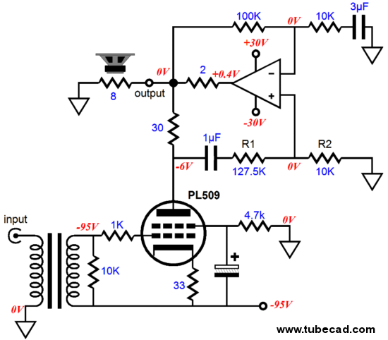
The solid-state power amplifier now has an AC gain of 11, as (100k + 10K) / 10k equals 11. The voltage divider resistor values have been changed to compensate for the newly added gain. Have we arrived? Well, we are close to something that I would actually like to assemble, but not quite there yet. Still, this side trip got me thinking about some of the hybrid impedance-multiplier circuits in general and, in particular, the impedance-multiplier circuits that I covered back in blog 171. Returning to unity-gain power IMC buffers, the following circuit is a hybrid 30:1 impedance-multiplier circuit that makes the 8-ohm loudspeaker appear as a 240-ohm load to the vacuum tube.
I wasn't alone in considering this sort of topology, as one TCJer wrote asking me if a similar circuit could be modified to use a popular gainclone chip power amplifier, such as the LM1875 or LM3886, which was not unity-gain safe. After a few e-mail exchanges, I realized that if this extremely capable fellow was having a difficult time figuring out design issues with this design, just about every other reader would also have a hard time with it.
IMC Baby Steps
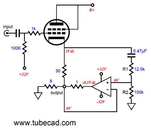
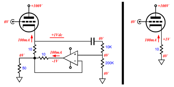
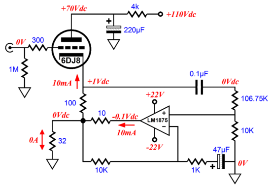
Since the tube's cathode resistor (Rk) and the series resistor (Rs) at the solid-state power amplifier output both equal the same value, 10 ohms, the impedance-multiplier circuit's impedance magnification is 2, as (Rk + Rs) / Rs equals so the multiplier ratio. Thhus, the 50-ohm load appears as a 100-ohm load to the tube. And since we wish to deliver all of the tube current swing, from 0mA to 200mA , the output voltage swing must equal 200mA against 100 ohms, or 20Vpk. This means that when the tube is pulling up 200mA, the solid-state amplifier must also be pulling up 200mA, resulting in 400mA into the 50-ohm load, which in turn develops a 20Vpk upward voltage swing. When the tube ceases to conduct, the solid-state amplifier must pull down by 400mA, ensuring a symmetrical negative voltage swing of -20Vpk. We can derive a formula to give us the peak voltage swing, if we feed it the load impedance and the Rk and Rs values. Vpk = 2Iq(Rk + Rs)Rload / Rs Once we know the peak voltage swing, we can divide this result by the actual load impedance to find the peak current swing, which we will need to determine the optimal impedance multiplying ratio to use. But I fear these steps may already prove too big, so let's review what the tube sees as the load is driven.
At idle, the tube only sees a 10-ohm cathode resistor, as no current flows into the load. Note how the power amplifier must also conduct 100mA to keep the output at 0V, which means that its DC offset at idle is -1Vdc.
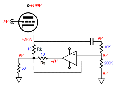
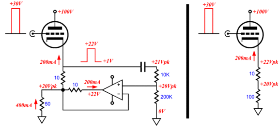
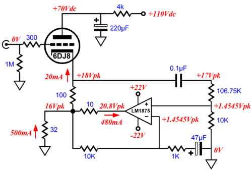
At +20Vpk of output, the tube effectively sees a load at its cathode of 110 ohms, 10 ohms from its cathode resistor and 100 ohms from the doubled load impedance. Note how the cathode voltage climbed from +1V to 22Vpk, a voltage swing of 21Vpk. Also note how the solid-state amplifier delivers the same 200mA of current into the load.
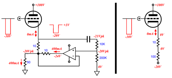
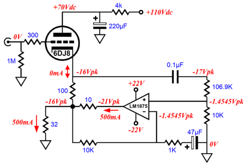
At -20Vpk of output, the tube still effectively sees a load at its cathode of 110 ohms, but the tube has ceased to conduct. Note how the solid-state amplifier now must deliver the full 400mA of current into the load. As can readily be gleaned from these three examples is that the tube and solid-state power amplifier are equal partners in driving the load, as we set the impedance-multiplier circuit ratio to 2. The higher the ratio, the more power the solid-state power amplifier contributes.
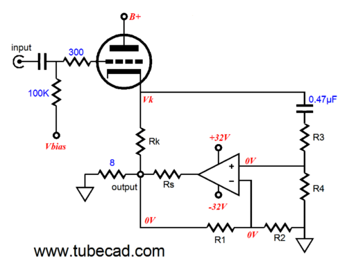
What is a bit more confusing is how the two-resistor voltage divider (that samples the voltage swings at the tube's cathode) works. The first thing to consider is the baseline DC voltage at the cathode, as it is from this reference that the cathode's voltage swings start from and which must be subtracted from the peak voltage swings. Also note how the capacitor in series with the voltage divider ignores the DC voltage at the cathode. The formula for finding the right voltage divider values is much like the previously given one, but expanded to include those cases wherein we get voltage gain from the solid-state power amplifier: If the solid-state power amplifier offers no voltage gain, then we just ignore R1 and R2 in the above equation.
IMC Headphone Amplifier Example
The peak voltage swing is 16Vpk and the peak current swing is 500mA. The 6DJ8 idles at 10mA and the impedance-multiplier circuit magnifies the 32-ohm load into a 352-ohm load, as far as the triode is concerned. (The 100-ohm cathode resistor must be added to the 352 ohms when laying out a loadline on the plate curves.) The LM1875 is the gainclone 5-pin, TO-220-packaged chip amplifier from National Semi. Here is the overview from its datasheet:
As you can see, using this power amplifier in a headphone amplifier is a bit of overkill. But then, isn't that what our hobby is all about? (I have never played with this power OpAmp, but my friends tell me that it sounds surprisingly good.) Now, let's look at the voltage relationships within the circuit when it output swings fully positive.
Looking at the voltage relationships when it output swings fully negative, reveals how the tube has completely turned off.
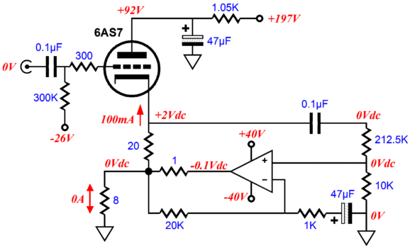
Where many readers are going to stumble is seeing where the -17Vpk voltage swing at the top of the voltage divider comes from, as the load only sees a -16Vpk swing. Remember that the tube's cathode started at +1Vdc, so when it swings down to -16V, the cathode has covered 17 volts of voltage potential. Do not forget that this is a unity-gain buffer, although the LM1875 is configured for a gain of 11. The other half of a 6DJ8 could be used to provide voltage gain. In addtion, the LM1875 will require its Zobel network at its output (1 ohm and 0.22µF). What about loudspeakers? (I myself would assemble a speaker that held four fullrange 8-ohm drivers in series, with a 32-ohm impedance.) As this circuit stands, it could not deliver much wattage into an 8- or 4-ohm load, as the 10-ohm series resistor consumes too much voltage. On the other hand, if the series resistor is reduced to 1 ohm, then, at the least, an 8-ohm load could certainly be driven. But, then, a larger, beefier tube should be used, such as a 6AS7 or 6C33, as 10mA is a pitiful amount of current. Here is such a design example:
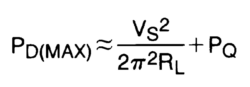
Of course, this is where a much more robust tube and a beefier gainclone chip should be used, such as the LM3886. By the way, while rereading a bunch of National Semi datasheets, I kept encountering the following formula:
Where Pq is the power dissipation at idle and Vs is the entire pin-to-pin power supply voltage, so an amplifier runs on +/-40Vdc rails, the Vs equals 8oV. Well, at first I didn't think it is right. (Trying to figure out what the amplifier will actually dissipate in the worst case is not easy, as we listen to music, not sine or square waves.) The formula I remember is as follows: Pd(max) = Pq + (0.707 x 0.64 x Vrail)² / Rload where Vrail is positive rail voltage. Well, both formulas yield the same results.
Next Time
//JRB |
I know that some readers wish to avoid Patreon, so here is a PayPal button instead. Thanks.
John Broskie
E-mail from GlassWare Customers
High-quality, double-sided, extra thick, 2-oz traces, plated-through holes, dual sets of resistor pads and pads for two coupling capacitors. Stereo and mono, octal and 9-pin printed circuit boards available.  Aikido PCBs for as little as $24 http://glass-ware.stores.yahoo.net/
Support the Tube CAD Journal & get an extremely powerful push-pull tube-amplifier simulator for TCJ Push-Pull Calculator
TCJ PPC Version 2 Improvements Rebuilt simulation engine *User definable
Download or CD ROM For more information, please visit our Web site : To purchase, please visit our Yahoo Store: |
|||


| www.tubecad.com Copyright © 1999-2011 GlassWare All Rights Reserved |