| John Broskie's Guide to Tube Circuit Analysis & Design |
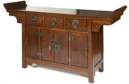
18 February 2007 Happy Chinese New Year! Speaking of things Chinese, I greatly admire the Chinese aesthetic—well, the ancient aesthetic at least. I revel in all the wavy lines, red and black lacquer, brass metalwork, and flying dragons. Yet, I have to agree with the popular disdain for contemporary Chinese design, particularly modern Chinese audio gear. Yes, I know some are thinking, “Is there any contemporary audio gear not made in China?” And, of course, I acknowledge that many, if not most, American, European, and Japanese audio gear is made in China today; but I am talking about the homegrown Chinese audio efforts. What I do not get is why the indigenous Chinese audio companies do not fall back on their magnificent history of high civilization and artistic accomplishment. In other words, I would love to see a preamp or power amplifier built as intricately and beautifully as an antique Chinese jewelry box, whose construction presents few parallel lines and many graceful embellishments. Of course, such a masterpiece would be filled with tubes and the best that solid-state has to offer, but it would still be absolutely authentic to China, the real China, the China of centuries past. Imagine if the Chinese had invented the triode 500 years ago. Imagine what their 300B would have looked like. Imagine the beautiful audio gear. Instead, what we get today is cheesy Chinese copies of the worst the West has offered, the razor-sharp faceplates, and rectilinear metal boxes.
Current-output tube amplifiers
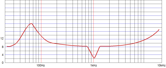
Let’s consider the average loudspeaker’s impedance curve. Upward spikes accompany the bass resonance; downward spikes, poorly designed crossovers. The voltage amplifier finds the woofer's rising impedance at resonance an irritation, as the amplifier’s fixed output voltage can only deliver a fraction of the current into the high-impedance load; and thus, just a fraction of its power. At the same time, the voltage amplifier (if sturdily built) can easily ride over impedance dips, as it can deliver the necessary current into the low impedance. On the other hand, the current amplifier easily tackles the speaker’s impedance spike at resonance, as it delivers a fixed current into the high impedance by raising its output voltage; the impedance dip, however, causes problems, as the current amplifier will deliver its fixed current into the low impedance, which will result in little power being imparted to the loudspeaker. Poorly designed crossover-induced impedance dips can be eliminated by careful crossover design; but the impedance peak at resonance is much tougher to cure. Transmission-line loading, if designed properly, will flatten the curve substantially. Another strategy might be to use multiple woofers. For example, place four woofers in series parallel, so the resulting total impedance remains unchanged. Then give each woofer its own sealed chamber. If each chamber were the same volume, the sum of the four impedances would equal the same as one driver’s impedance. But if each driver worked into a different-sized volume, the resulting impedance would be flatter, as each woofer would resonate at a different frequency and each woofer’s flat portion of impedance would shunt the another woofer’s impedance spike.
Of course, if you are bi-ampping and the subwoofers are taken care of by a huge solid-state amplifier, then the resonance-induced impedance spike is not a problem that our current-output amplifier will have to face.
Current-output amplifier design issues Now current gain is similar to voltage gain, but not identical. For example, a transformer-coupled tube amplifier may develop 30V of peak output (56W) because of a 1V peak input signal, which would seem to imply a voltage ratio of 1:30, but this final ratio ignores the output transformer’s voltage-dividing function. In other words, although the ratio of output voltage over input voltage is 30, the internal voltage ratio must be much higher for the tube circuit, as the output transformer greatly divides the voltage across the primary before coupling it to the secondary. For example, a winding ratio of 20:1 results in an impedance ratio of 400:1, which means that an 8-ohm load is reflected back to the primary as a 3,200-ohm load. This same 20:1 winding ratio divides the primary voltage swings by 20, but multiplies current swings by 20. So, in order to get a 1:30 voltage-gain ratio, the tubes have to develop a voltage gain of 1:600 (imagine a transmitting-tube-based single-ended amplifier). Conversely, in a transformer-coupled current-output amplifier, in order to get a 1:1,000 current-gain ratio the tubes have to develop an internal current gain of only 1:50, as the output transformer will increase the current by twentyfold. Nonetheless, tubes are voltage-driven devices, so at some point the input current will have to be converted to voltage. For example, 1mA against a 47k resistor equals 47V, which divided into 600V results in only 13x of voltage gain. Last time, I mentioned that pentodes would hold several advantages over the triode in a current-output amplifier, as the pentode would yield a higher PSRR and a higher output impedance. An additional advantage that should be stressed is a big increase in power output. Just as a pentode-based voltage amplifier can put out twice the wattage as a triode-connected-pentode-based voltage amplifier, a pentode-based current amplifier could easily double the wattage over a similar triode-based current amplifier, and for the same reason: bigger voltage swings before hitting the positive-grid-voltage limit.
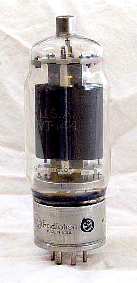
Everyone knows how expensive NOS 211s and 845s have become, but for under $60 you can pick up NOS 813s, which look just as cool and could yield a great gob of power into your loudspeakers.
Living in a voltage-centric world By varying the resistance that a light bulb presents to that fixed voltage, we vary both the amount of light and the amount of power consumed (power converted into heat). The higher the wattage of the light bulb, the lower the resistance of its filament, as the lower resistance increases the current draw against a fixed voltage, which when multiplied against the fixed voltage, yields greater power consumption. Power = V² ÷ R Because the wall voltage is fixed, the worst thing that can happen to the electrical wiring in your house is to have a direct short across the wall socket, as it would require the wall current to climb to infinity. Fortunately, a fuse will blow before the transformer that feeds your block blows.
Now, on the other hand, if most of us thought primarily in terms of current, rather than voltage, we might have differently setup our electrical power stations and houses and electrical appliances. Power stations would put out a fixed current, not a fixed voltage: 10 amperes, let’s say. All the wall sockets in your house would be wired in series, so that all of your appliances would see that same fixed current flow. If a socket were not in use, a shorting plug would have be inserted lest (like poorly designed Christmas tree light strings) none of the appliances in your house would work. In the same way, the off switch would just short the power cord’s two wires.
Each appliance in use would see the same fixed current draw and a differing voltage. For example, by varying the conductance that a light bulb presents to that fixed voltage, we would vary both the amount of light and the amount of power consumed. The higher the wattage of the light bulb, the higher the resistance of its filament, as a higher resistance would compel a higher voltage drop across the light bulb, which multiplied against the fixed current would yield a higher power dissipation. Power = I² • R Because the current is fixed, the worst thing that could happen in your house would be to have an open connection across the wall socket, as it would require the wall voltage to climb to infinity. Why wasn't this constant-current approach—the current-centric viewpoint— adopted? In a world of all-too-imperfect conductors, the near perfect infinite impedance presented by the off switch wins hands down. Besides, the voltage leaving the power station would have to be dizzyingly high, say several tens of million volts to power a city, as each power consumption--each toaster and night light--would entail a voltage drop, which would contribute to the sum of all the series voltage drops. (Actually, each house would probably allotted a fixed 117A feed, and the power meter would read just the same as it does today.) Imagine, however, that we did adopt the fixed-current approach to wiring a city. In this alternative universe, transistors—with their ridiculously low breakdown voltages—most likely wouldn’t have toppled vacuum tubes as the best commercial choice for amplifiers. Of course, in this same universe, some nutters would argue for using voltage amplifiers instead of current amplifiers; they would point out what a great output device the transistor would make in such an amplifier, as it could deliver gobs of current at low voltages. //JRB
|
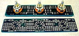
The TCJ Stepped Attenuator The center knob controls both channels, and offers six large decrements; the flanking knobs offer six fine decrements for each channel, creating a volume control and balance control in one easy-to-use stepped attenuator. This clever attenuator uses fewer resistors (only 32) than would be expected from a conventional 32-position stepped attenuator, as two series attenuators would need a total of 72 resistors; and two ladder attenuators would require 140 resistors. In addition, the PCB holds dual sets of resistor pads, one wide and one narrow, so that axial (composition, wire-wound, and film) and radial (thick-film and bulk-foil) resistors can be used without extra lead bending. Although designed to go with the Aikido amplifier, it can be used anywhere a high-quality attenuator is needed, whether passive or active. For example, it would make a first-rate foundation to an excellent passive line box. Visit our Yahoo Store for more details: http://glass-ware.stores.yahoo.net/
High-quality, double-sided, extra thick, 2-oz traces, plated-through holes, dual sets of resistor pads and pads for two coupling capacitors. Stereo and mono, octal and 9-pin printed circuit boards available.
Designed by John Broskie & Made in USA Aikido PCBs for as little as $24 http://glass-ware.stores.yahoo.net/
The Tube CAD Journal's first companion program, TCJ Filter Design lets you design a filter or crossover (passive, solid-state or tube) without having to check out thick textbooks from the library and without having to breakout the scientific calculator. This program's goal is to provide a quick and easy display not only of the frequency response, but also of the resistor and capacitor values for a passive and active filters and crossovers. TCJ Filter Design is easy to use, but not lightweight, holding over 60 different filter topologies and up to four filter alignments: While the program’s main concern is active filters, solid-state and tube, it also does passive filters. In fact, it can be used to calculate passive crossovers for use with speakers by entering 8 ohms as the terminating resistance. Click on the image below to see the full screen capture.
Tube crossovers are a major part of this program; both buffered and un-buffered tube based filters along with mono-polar and bipolar power supply topologies are covered. Available on a CD-ROM and a downloadable version (4 Megabytes). Download or CD ROM
|
|||

.png)


| www.tubecad.com Copyright © 1999-2007 GlassWare All Rights Reserved |