| John Broskie's Guide to Tube Circuit Analysis & Design |
02 January 2018 Post 407
Happy New Year!
Special Thanks to the Special 61 Only those who have produced a technical white paper or written an article on electronics know just how much time and effort is required to produce one of my posts, as novel circuits must be created, SPICE simulations must be run, schematics must be drawn, and thousands of words must be written.
If you have been reading my posts, you know that my lifetime goal is reaching post number one thousand. I have 593 more to go. My second goal is to gather 1,000 patrons. I have 939 patrons to go. If you enjoyed reading this post from me for the last 18 years, then you might consider becoming one of my patrons at Patreon.com. It would make a big difference to me. Thanks.
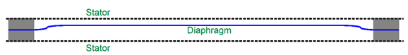
Digital Electrostatic Loudspeaker My first thought was that 16 long strips of electrostatic diaphragm could each be driven by either a high-voltage positive or negative voltage, with no analog tracing of an input signal, but the binary flipping between three states: negative, neutral, or positive. Each strip would get its own bit to translate into motion. At full positive, all the 16 strips would push forward; at full negative , all would push backward. In other words, this speaker would itself be a DAC, a Digital to Analog Converter, a DAC that converted the digital code into analog sound at our ears. Of course, at least 16 high-voltage switching devices would be needed and would have to be internal to each loudspeaker. How would the volume be controlled? Digital volume controls are common and they use software to boost or attenuate the digital code before it reaches the DAC. The problem with this approach is that with a 16-bit signal and a 16-bit DAC, the attenuation is not always lossless. (On the other hand, a 16-bit signal fed to a 24-bit DAC can undergo a lossless digital attenuation down to -48dB, before we must throw away musical data.) Is there any other approach? Yes. The bias voltage sets the efficiency in an electrostatic loudspeaker, so by raising and lower this voltage we could control the volume. Here is a graph from Ronald Wagner's book, Electrostatic Loudspeaker Design and Construction, which shows the relationship between an electrostatic loudspeaker's SPL and its bias voltage.
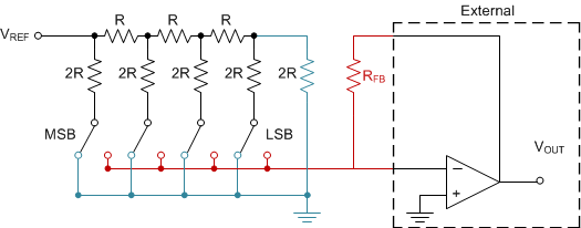
In a way, this arrangement would mimic an MDAC. What is an MDAC? MDACs are fanatically interesting DACs. The "M" stands for multiplying. The way the MDAC works is that it puts out current and is filled with resistor networks and switches. Just how much current it puts out is dependent upon two things: the digital signal and the external reference voltage applied to the MDAC. Internally, the MDAC presents a fixed resistance between its reference input voltage pin and the DAC's output pin.
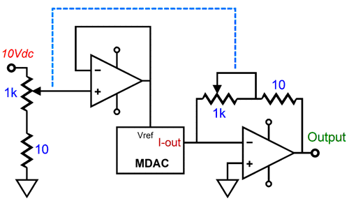
Click on schematic to see Texas Instruments article on MDACs Assuming an internal resistance of 1k, the math becomes easy. For example, if the reference voltage is 10Vdc, the peak output current from the DAC will be equal to 10V/1000 ohms or 0.01A or 10mA. If we lower the reference voltage to 1V, however, the peak output current will equal 1mA; lower the voltage to 0.1V, 0.1mA. At all times we retain the full 16 bits of resolution, but we can attenuate the analog output signal by -20dB and -40dB by shifting the reference voltage down by a factor of ten and then by a factor of one hundred. In fact, you can use a negative reference voltage and even an AC signal. One thought that I have long entertained was that a dual-section linear potentiometer could be used for a volume control. The first linear potentiometer would feed a varying DC voltage to the voltage regulator that fed the MDAC's reference input, while the second potentiometer would serve as the I-to-V resistor for the OpAmp that converts the current output into voltage output. Thus, at 50% of rotation, we would get -12dB of attenuation, not the -6dB that one linear potentiometer would deliver. At 25%, we get -24dB of attenuation; at 12.5%, -36dB; and at 6.25%, -48dB.
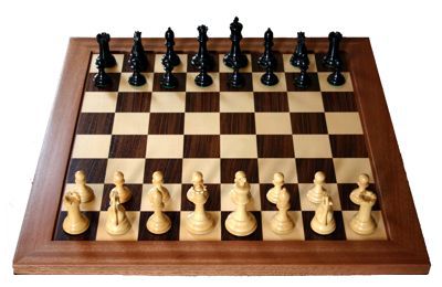
Returning to the digital electrostatic loudspeaker, each successive strip would have to put out twice the output as the preceding strip. Oops! I quickly realized that I had run into the rice on the chessboard problem. It's an old story of uncertain origin, but probably originating in India and then traveling to Arabia.
The story, as I first heard it, dealt with the invention of chess. An Indian king was so delighted by the new board game that he offered its creator a reward of his choosing. The fellow made what seemed like a modest request: he only wanted the king to place one grain of rice on the first square and then two on the second square and four on the third square and so on until all 64 squares were covered with rice. The king eagerly agrees and is happy to have to pay just a cup of rice for so fine a game. But soon enough the king discovers that there is not enough rice in his kingdom or even in the world to pay the man, so the king has the smart aleck executed. How much rice would be needed? The answer is equal to 2 to the 64 power minus 1 or 18,44,674,407,3709,551,615, which is a bunch of rice. One pound of long-grain rice holds about 29,000 grains, so this would mean that 6,360,946,232,313,638.5 lbs would be needed or 3,180,473,116,156 US tons. Today, India is the second biggest producer of rice, but its yearly 116,845,000 US tons of rice yield is over 27,000 times too small to cover the chess board according to the king's agreement. Another way to think of it is that this amount of rice would equal giving every man, woman, and child on Earth, all seven billion of us, 90,870 lbs of rice each. If you are ever offered either $1,000,000 or one penny that doubles each day for a month, take the pennies, as even February yields far more money.
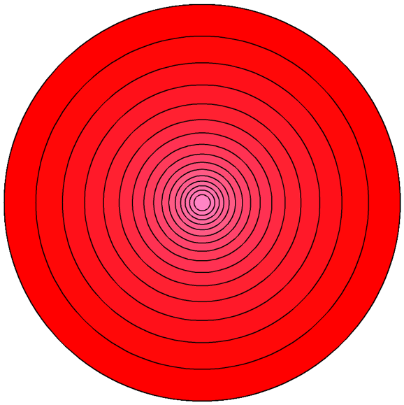
With the 16 long strips of diaphragm, the second strip must put out twice the pressure as the first, and the third strip must put out four times the pressure... and by time we get to the 16th strip, it would have to put out 32,768 times the pressure. Good luck. Well, what if we made the each successive strip twice as wide as the previous one? Once again, good luck, as the 16th strip would have to be 32,768 times wider than the first strip. Even if the first strip was only 1mm wide, the last strip would be 32.77 meters wide. Okay, what if we do not make all the strips equal in length, say using squares rather than long strips? This would certainly help, but we still end up with a big 16th square. How big? If the first square was 1in by 1in, the last square would have to be 15ft square. Then it came to me: why not increase the area not by two but by the square-root of two, while increasing the applied signal voltage by the square root of two? This way each successive segment would effectively put out twice the pressure as the preceding one. The shape that came to my mind was of 16 concentric rings.
The outer most ring would get the applied voltage and it would hold the greatest area. Here is the results from an Excel spreadsheet I made.
The area and diameter can be in millimeters or centimeters or inches or feet, as long as the ratios are observed. A 28 centimeter digital electrostatic speaker would make a fine computer speaker, while a 28 inch version might play loud enough for a small room. And the 1810V peak voltage requirement is high, but not crazy high. Indeed, we might be able to scale down, so the first cell received +/-1V pulses, while the last received +/-181V pulses. These voltages move us down into the range of optoisolators-triac devices.
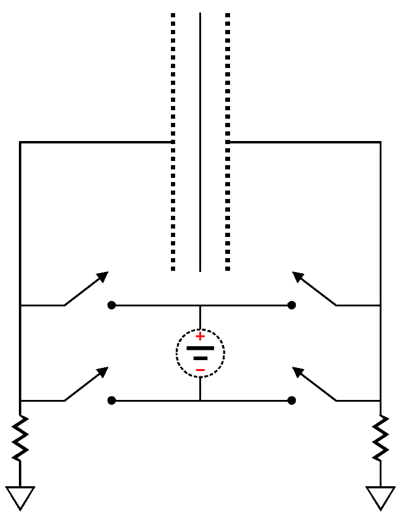
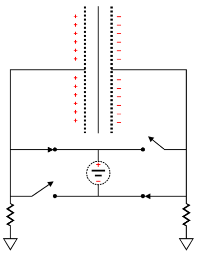
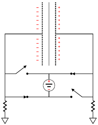
By flipping the switches we can achieve three voltage states on each stator: positive, ground, negative. The floating power supply is not grounded; and the resistors bleed away the charge developed on the stators, restoring them to a neutral or ground potential.
The stators could be made from perforated PCB material, as the 16 rings would be easy to etch or to router into the copper side.
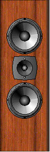
Assuming a 28 inch in diameter digital speaker, how comparable would that be to typical dynamic speaker? Well, the average 12 in woofer offers almost 80 square inches or 500 square centimeters of surface area. Now, 615 square inches seems to be eight times bigger, but effectively it is not. Why Not? The outermost ring produces slightly more pressure as all the other 15 rings combined, so a truer evaluation of surface area would be twice the 16th ring's area of 181 square inches or 362 square inches, which is four and a half times greater than the 12-inch woofer's area. In other words, the rings do not need to move very far to make some decent SPLs.
At the same time, we must be careful not to think of this digital speaker being too analogous to a regular analog speaker. For example, all the rings must produce the lowest frequencies and the highest frequencies—no woofer, no midrange, and no tweeter action here, as all must follow square-wave movements at 44,100 times a second. What about low-pass filtering that most DACs require? The electrostatic diaphragm itself will impose a high-frequency limit due to the panel capacitance and the diaphragm's own mass. If further filtering is needed, a thicker grill cloth might do the job. What would such a digital speaker sound like? I do not know, but I would love to hear one. But, John, what about all my 96kHz, 24-bit recordings? I hate to open this can of worms, but your 24-bit files will sound pretty much the same as they do now, if not better played through a 16-bit speaker. If you stop and think about it for a second, you realize that all those 32-bit DACs out there are never R-2R DACs, but delta sigma designs. A good R-2R DAC costs far, far more than a delta sigma DAC and it is intrinsically far, far quieter; moreover, it is fundamentally simpler as well. Very few audio companies sell true R-2R DACs, with Schiit multi-bit DACs making the audio world go justifiably gaga. The ultimate DAC is the thermometer-coded DAC. This DAC does not exist in audio, as a 16-bit thermometer DAC would require 65,535 different-valued resistors, one for each possible 16-bit level. Instead, we get delta sigma DACs. Is that a problem? Sadly, yes. None of the 32-bit delta sigma DACs come close to the predicted signal-to-noise ratio of -162dB. Nor should you expect it to actually resolve down to 0.00000000023V increments. Why then is everyone making 32-bit DACs? The same reason anyone makes anything to sell: because you will buy one, believing it must be far better than the old 24-bit DACs. If you have the time, check out the specs for the Bur-Brown (TI) PCM1792 24-bit DAC and the five-year newer and 32-bit DAC, the PCM1795, which was a technical step backwards, delivering worse SNR and more distortion and less output current, but no doubt a marketing triumph. (The newer 32-bit also cost 1/5th as much as the older, better 24-bit DAC. Sadly, the marketing logic is compelling.) But, John, my 24-bit music files sound better. I don't doubt that they do, as I also prefer them over 16-bit files, but I am sure the better sound is the result of the higher sampling rate and the less steep low-pass filtering applied. (If I had to bet on the best compromise between file size and audio excellence, it would be 18-bits at 60kHz, assuming a true 18-bit R-2R DAC was used.)
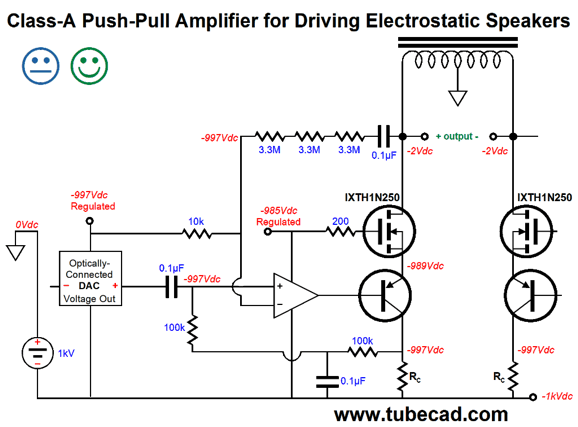
More Direct Drive Here is an example of an electrostatic power amplifier similar to one that appeared in post 404 and it that shows us a path we could follow.
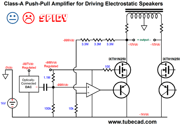
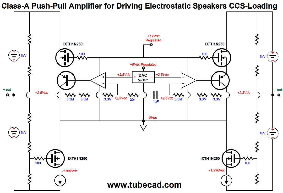
The amplifier makes use of a center-tapped inductor to load the two N-channel MOSFETs, which effectively doubles the power-supply rail voltage, but the inductive loading does limit us to strict class-A, push-pull operation. Note how the MOSFET is driven through its source, not its gate. In other words, this arrangement is much like a grounded-grid amplifier, except that a MOSFET is used in place of a triode. All the same benefits accrue, such as no Miller-effect capacitance, no phase inversion, and wide bandwidth. Of course, the same liabilities present themselves, such as low input impedance and dang-low input impedance. Did I just repeat myself? Indeed, I did, but I thought this liability important enough to repeat it for added emphasis. Because the MOSFET's source presents so low an input impedance, the we use the PNP transistor to drive it, rather than the OpAmp's output. Also note how the idle current is set by the negative feedback loop monitoring the voltage drop across both the center-tapped inductor's DCR and the series drain resistor. Thus, no happy face, as this setup might work just fine in SPICE, but reality is sure to disappoint, for the 1kV power-supply rail voltage will vary with the wall voltage variations and getting the two sides to balance each other in current draw is unlikely. A workaround is shown below.
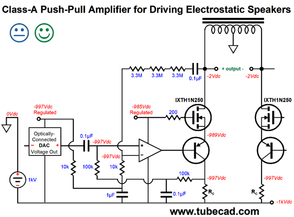
Now, the current flow through the MOSFET is measured by the voltage drop across the collector resistor. The OpAmp compares this voltage to the reference voltage, i.e. the regulated 3V that feeds the analog portion of the DAC. If you were truly bold, you might this configuration instead.
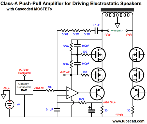
"Look Ma, no coupling cap." That's right: the 10k gain-setting feedback resistor terminates right into the regulated power supply voltage. SInce this amplifier's output is a balanced-differential one, any common-mode signal, such as noise leaking from the DAC's voltage regulator, should cancel at the stators. Maybe. Returning to the schematic shown in post 404, we see the OpAmp configured as an inverting amplifier.
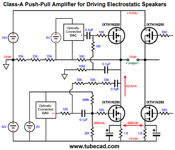
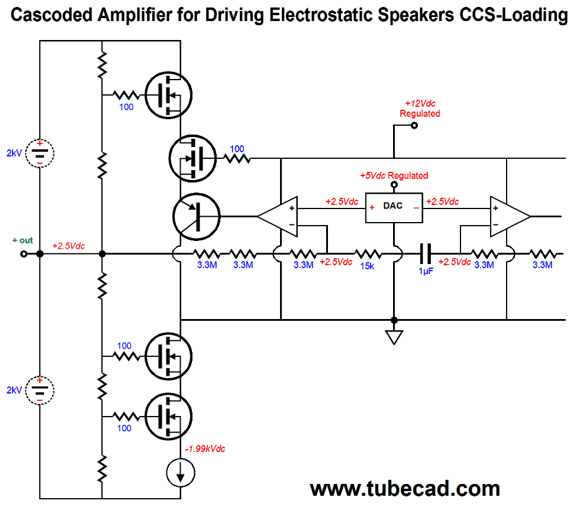
The MOSFETs were cascoded to allow us to both use a greater negative power supply voltage and to spread the heat generated across the two MOSFETs in series; this approach also allows us to use cheaper, lower-voltage MOSFETs. The coupling capacitor at the end of the feedback resistor string prevents the DAC's output DC offset from being diminished. Note that the DAC's output DC couples to the 10k gain-setting resistor, so the OpAmp can use this voltage as its voltage reference for setting the idle current through the MOSFETs. The two 100pF capacitors are actually essential, but I left then out of most of the schematics to aid conceptual clarity; they allow us to overcome the MOSFET's high input capacitance when trying to swing big voltages at high frequencies. How do we let the amplifier break out of the super-nice gated community of class-A operation and move it into the plainer, more vibrant but troubled class-B suburbs? Why, for God's sake, why? For the same reason we do not all live in gated communities: the expense. Class-A operation is expensive, in heat and weight and money. In contrast, class-B and class-AB are cheap, which is why almost all amplifiers—that are not class-D types—are class-B types. The first thing that must go is the center-tapped inductor. What must be added is an extra set of power MOSFETs and a bipolar power supply. The following design still runs in class-A, which allows for easy auto-bias of the idle current, but more importantly shows how the two extra MOSFETs can be used that will allow for push-pull operation.
The rail voltages are doubled and two N-channel MOSFETs are online. Note that at least three voltage-out DACs are needed per channel: two floating DACs and one balanced-output DAC at the bottom. It may not look like it, but two negative-feedback loops are employed per side. This arrangement tends to blow some reader's minds, as happened when in 2015, in post number 328, I showed the following circuit.
The above circuit is a grounded-cathode amplifier that does not invert the input signal phase and which uses resistors, Rk and R as feedback resistors. And as recently as post 384 I showed this head-scratcher:
The 100-ohm and 2k ohm resistors define a negative feedback loop, which set the single-ended amplifier's gain. In contrast, the bottom negative feedback loop is simple enough in the push-pull MOSFET amplifier shown earlier, as the bottommost MOSFETs are configured as a common-source amplifiers that inverts the gate signal at its drain, which makes the bottom MOSFETs function as simple inverting amplifiers. Both the top and bottom MOSFETs get their mojo from their transconductance against the voltage-out DAC's output signal. Sadly, because we desire such huge voltage swings from an electrostatic power amplifier, not much feedback actually can be applied. The workaround is throw some more into the mix, but lets get there in baby steps.
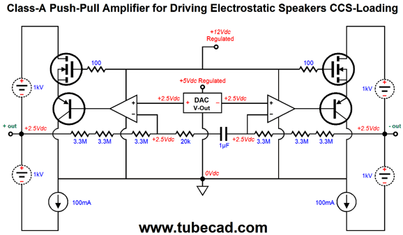
The above balanced-output amplifier uses two floating power supplies and two constant-current sources (CCS). As one MOSFET increases its current conduction, it pulls sown it side's output voltage; as it decreases its current conduction, it lets the CCS pull output voltage up. Yes, we are back to class-A, as we are taking baby steps. Where you buy a 2kV CCS? You don't, you build one. Here is how it's done.
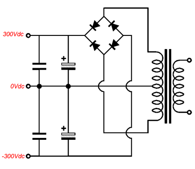
The bottom MOSFETs cascode with the constant-current sources, leaving a 10V window of voltage to work within. The two OpAmps provide the needed extra gain to drive the two negative feedback loops. The 1µF capacitor DC isolates both sides, so each OpAmp can center its side's DC offset. As shown, the DAC's DC offset voltage is relayed to the two balanced outputs, which would be a problem with dynamic speakers, but makes little difference with an electrostatic load. Each channel requires four floating power supplies. Of course we could use two of the following topologies, so only two floating secondaries per channel would be required.
The key point here is that the power supplies cannot be grounded, as they must be free to swing up and down hundreds of volts. The bottom MOSFETs are configured as high-voltage constant-current sources. Yes, we are creating a push-pull amplifier out of two single-ended stages. As it stands, the MOSFETs will get plenty hot. The workaround is to add more MOSFETs in cascode.
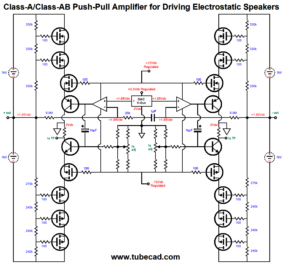
Now, four MOSFETs divide up the 2kV of power-supply voltage. Finally, we can move on to a design that can be run in either class-A or class-B or class-AB. The first step will be to replace the bottom N-channel MOSFETs with P-channel MOSFETs.
The first thing that stands out is that we have added two NPN transistors, which drive the P-channel MOSFET sources. The second thing we notice is that these NPN transistors are driven indirectly by the OpAmps through the 1kµF capacitors. The two potentiometers set the idle current through each side. Two test points are provided, so that the voltage drop across the two collector resistors can be measured. It may seem elaborate, but I do fear the potentiometer losing contact during adjustment and the added resistors maintain a DC voltage path in that event. The final standout feature is that eight P-channel MOSFETs are used, while only six N-channel MOSFETs are used. Why the discrepancy? P-channel MOSFEts rarely exceed a -500V voltage limit, with -600V being the current maximum available, such as the IXYS IXTH10P60, a 300W MOSFET. The eight P-channel MOSFETs buys us up to 2400 volts to work within. Of course, now that the DAC is located at ground potential, not sitting at -1,000Vdc, we can forgo the DAC and use balanced line-level inputs. I believe that I have finally emptied my sketchbook of ideas for electrostatic-drive amplifiers. So, next time, I plan on returning to tube-based single-ended amplifiers.
//JRB
User Guides for GlassWare Software Since I am still getting e-mail asking how to buy these GlassWare software programs:
For those of you who still have old computers running Windows XP (32-bit) or any other Windows 32-bit OS, I have setup the download availability of my old old standards: Tube CAD, SE Amp CAD, and Audio Gadgets. The downloads are at the GlassWare-Yahoo store and the price is only $9.95 for each program. http://glass-ware.stores.yahoo.net/adsoffromgla.html So many have asked that I had to do it. WARNING: THESE THREE PROGRAMS WILL NOT RUN UNDER VISTA 64-Bit or WINDOWS 7 & 8 or any other 64-bit OS. One day, I do plan on remaking all of these programs into 64-bit versions, but it will be a huge ordeal, as programming requires vast chunks of noise-free time, something very rare with children running about. Ideally, I would love to come out with versions that run on iPads and Android-OS tablets.
//JRB |
Kit User Guide PDFs
And
High-quality, double-sided, extra thick, 2-oz traces, plated-through holes, dual sets of resistor pads and pads for two coupling capacitors. Stereo and mono, octal and 9-pin printed circuit boards available.
Designed by John Broskie & Made in USA Aikido PCBs for as little as $24 http://glass-ware.stores.yahoo.net/
The Tube CAD Journal's first companion program, TCJ Filter Design lets you design a filter or crossover (passive, OpAmp or tube) without having to check out thick textbooks from the library and without having to breakout the scientific calculator. This program's goal is to provide a quick and easy display not only of the frequency response, but also of the resistor and capacitor values for a passive and active filters and crossovers. TCJ Filter Design is easy to use, but not lightweight, holding over 60 different filter topologies and up to four filter alignments: While the program's main concern is active filters, solid-state and tube, it also does passive filters. In fact, it can be used to calculate passive crossovers for use with speakers by entering 8 ohms as the terminating resistance. Click on the image below to see the full screen capture.
Tube crossovers are a major part of this program; both buffered and un-buffered tube based filters along with mono-polar and bipolar power supply topologies are covered. Available on a CD-ROM and a downloadable version (4 Megabytes). |
||||||||||||||||||||||||||||||||||||||||||||||||||||||||||||||||||||||||||||||||||||||||||||||||||||||||


| www.tubecad.com Copyright © 1999-2018 GlassWare All Rights Reserved |