| John Broskie's Guide to Tube Circuit Analysis & Design |
| 22 December 2013 Updated December 26 2013I have to thank Zygmunt Jerzyński of hiend-audio.com for spotting an error in my original post on the hybrid single-ended power amplifier shown at the bottom of the page. Thanks Ziggy. The power amplifier does not require a negative power-supply rail (I went temporally crazy.) I made the corrections and I have added an auto-bias circuit that uses a TL431 shunt regulator. Merry Christmas
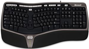
Yes, it's been a crazy long time, since my last post. And it's been crazy for me. One damn thing after another. For example, a few weeks ago, I suffered some water damage in my basement, but only over a very small area; unfortunately, it was the area where my computer sits. One of my LCD monitors and my keyboard were soaked; the monitor I was able to save. The keyboard died and could not be resurrected, well at least not by me. Thus, I was forced to use one of those cheesy little keyboards that come with new computers. You know the ones I am talking about; they are less than 18in wide and about 6in tall—so tiny that they would only work well for a female under five feet tall, with delicate fingers. Either my hands are too big or my shoulders too wide or both, however, as I could not type with two hands on the tiny keyboard; in fact, I could barely type at all on it. (If this was the only keyboard size available, I doubt that I would even own a computer. It just wouldn't be worth the hassle.)
Well, my new and dry Microsoft Natural Ergonomic Keyboard 4000 has arrived (after days and days of waiting) and I am ready to go. (Not that the Microsoft keyboard is perfect, as it could be six to nine inches wider. It does, however, hold several wonderful buttons, such as one for bringing up the MS calculator and two for moving back and forward on web pages and in directories.)
Cute ACF-2 Project
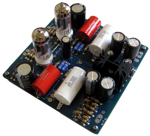
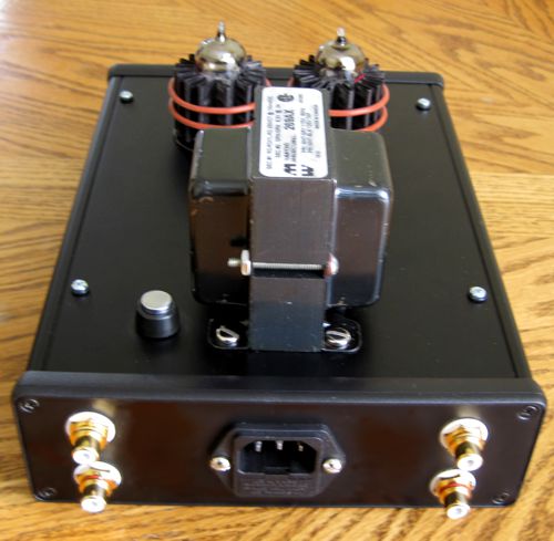
Do not be deceived, the unit is small, as the total width of the enclosure is just over 6 inches and it is a tad over 2 inches tall. The tubes are 6DJ8 types and the transformer is tiny.
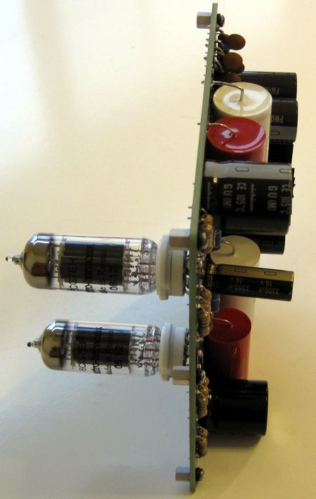
Other than the tubes and their sockets, all the parts are soldered on the bottom side of the PCB.
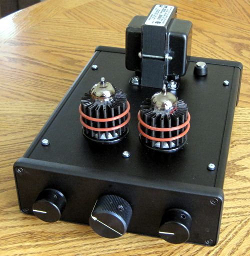
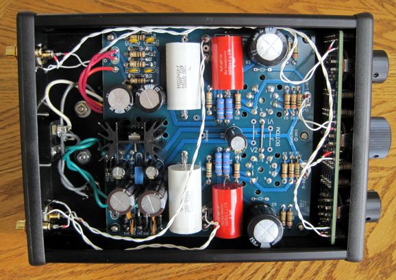
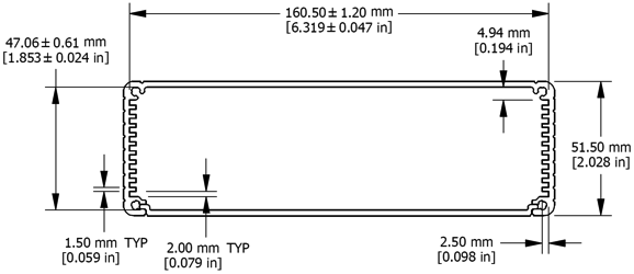
Note the 1/4in hex standoffs. The fit inside the Hammond 1455T2201BK enclosure is tight, so the 1/2in stands could never be used. (If the enclosure were just an extra inch in length and half an inch taller, life would be much easier.) Note how Hammond box is being used upside down as well, as the cover now appears at the bottom.
OK, I take that last sentence back, as I have just looked up the Hammond PDF for the enclosure and it shows the removable sheet as being the bottom panel, not the top cover. So, it seems that I have always been using these enclosures upside down; maybe in a past life I was an Australian. I should have taken a photo of the bottom panel, as it would show all the ventilation holes I drilled into it. In any case, the PCB and its standoffs can only fit as shown, as the side with the removable panel is a tad too narrow.
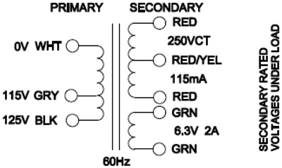
You can see that everything did fit, but it wasn't easy. Since taking this photo, I have tidied up the wiring, so do not worry. I wish that I had placed the power transformer, a Hammond P-T269AX, a little further back.
Speaking of the power transformer, I used the white and gray primary wires, which was a mistake, as my wall voltage runs over 122Vac. Why not go back switch to the white and black wires? I clipped the black wire, alas. Measure twice, cut once. I also used the 6.3Vac heater winding in a voltage doubler rectifier configuration, so that I could run the heater regulator with 12Vdc output, which halves the current flow and gives the regulator more voltage breathing room. I tried attaching the circuit's ground to the house ground, but this induced hum problems. My power amplifiers are grounded to the house ground, so if a tragic fault condition occurred and one of the ACF-2 bipolar power-supply rails shorted to the chassis, the interconnects to the power amplifiers would provide a shorting path through their ground wire or shield. No, it isn't optimal, but it is better than nothing. By the way, I tried using just a small capacitor to connect circuit ground to house ground and the hum problem reappeared. If I had the room, I would like to have tried a large-valued inductor.
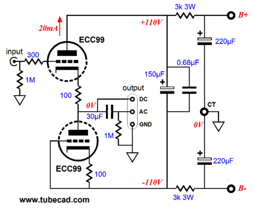
I used two JJ 6DJ8/E88CC tubes (not the JJ ECC99 shown above) and Pearl Audio tube coolers, MCF-9 types, which were not desperately needed to cool the tubes, as the tubes do not run all that hot. Still, cooler tubes does mean a longer life span. But the big reason I used them was that the Pearl Audio coolers always seem to improve the sound of the tubes. How is that possible? No doubt, by damping vibrations in the glass envelope or, perhaps, by shielding the triodes from RFI, which really does not make sense, as the tube coolers are not grounded. (Grounding them might prove an interesting experiment.) The three-knobbed stepped attenuator is one of my 5.8in wide A3-Mini designs. I used 1W carbon-film resistors throughout, for both the ACF-2 PCB and the attenuator. The center knob has since been replaced by one that more closely matching the smaller two flanking knobs. Note the positions of the two flanking knobs, which are the fine steps of attenuation for each channel. This is the way to the use a three-knobbed stepped attenuator. Start with the flanking knobs set to their mid position, then, adjust the coarse stereo volume knob in the center. Then move the two flanking knobs up or down as needed to set the correct volume or balance. I used -6dB and -1dB decrements. The coupling capacitors are Cornell Dubilier's 940C series 1µF/1kV capacitors, fit nicely and sound neutral. Now, the crazy thing is that I don't need this cute little buffer stage, as I own plenty of line stage amplifiers. I built it to see if it was possible to fit everything into such a small box and in the interest of cuteness for cuteness's sake. And cute it is. I was tempted to place two black rack-mount handles on the top to create a guarded area for the tubes, but I feared the unit becoming too busy looking. How does it perform? Really well. It may look like a toy, but it is a sonic powerhouse, reminding me of one of those derringer pistols that shoot two 45-caliber bullets. My DAC puts out plenty of gain, so a buffer-based line stage works well, easily driving my power amplifiers to full output. The troubling thing, troubling for me at least, is how much the ACF-2 improves the sound leaving the DAC. Just how it does this baffling. I don't run super long lengths of interconnect; thus, the DAC was never asked to drive high-capacitance loads, and the input impedance of my power amplifiers is higher than the load presented by the A3-Mini. Moreover, the ACF-2 introduces very little distortion, so I don't see how it can be providing much harmonic restoration. Yet, it does improve the sound, making the imaging go wider and deeper—and just sound more natural and substantial. As I say, quite troubling, but quite fun to listen to as well.
A Hybrid Single-Ended Amplifier
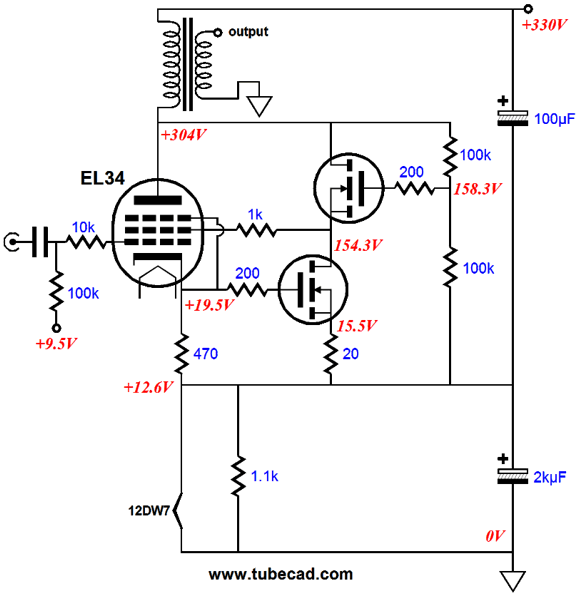
The first is that the EL34 output tube gets some help from the two cascoded N-channel MOSFETs, with the EL34 drawing just 15mA and the MOSFETs drawing 145mA (a total of 160mA). The second is that the EL34 is being run in ultra-linear mode; note the G2 connection to the the top MOSFET's source via the 1k resistor. The third is that the driver tube, a 12DW7, which is not shown in the schematic, derives its heater voltage and current from the idle current of the output stage, which equals 160mA (the 1.1k bleeds off 10mA of excess current). Fourth is that the EL34 uses both fixed and cathode bias to set its idle current. Fifth is that this output stage has received the Aikido treatment by the addition of the 100µF capacitor that attaches to the B+ connection, thereby injecting a small portion of B+ noise into the EL34's cathode, which creates an improved PSRR figure. There might be a sixth feature that I am presently blind to, which is likely, as my lunch awaits me. The 12DW7 is one just possible choice, as a 12AU7 or 12AT7 could work just as well, depending the the input and driver circuit used. (A peak voltage swing of about 11Vpk is needed to drive the EL34.) Adding an auto-bias feature is a worth goal and fairly easy, as the following schematic shows. 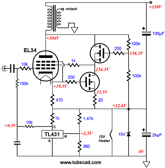
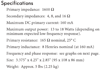
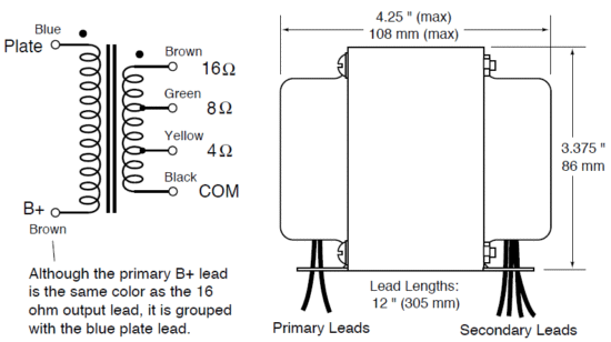
The TL431 voltage-reference/shunt-regulator varies its current conduction in an attempt to see exactly 2.5Vdc at its reference input. If more that 2.5V is present, its cathode is pulled down as it increases its current conduction, thereby decreasing the the EL34's grid voltage. If less than 2.5V is seen at the TL431's ref pin, then it decreases its conduction, causing the EL34's grid voltage to rise. The zener is a safety feature and normally does nothing. But if the input tube is missing from its socket or its heater element has suffered an open, then the zener will save the day, preventing an over voltage for both the 2kµF capacitor and the TL431. The TL431 and its voltage-divider resistors draw about 10mA of current, which added to the 12V heater element's 150mA current draw, brings the total current draw up to 160mA. The output transformer is not marked, as I don't want to give the impression that is the only one that could be used. Nonetheless, in my SPICE simulations, I used a UBT-1 transformer from One Electron. The UBT-1 is a great output transformer, which is why I own six of them. In this circuit design, it works well because of its unusually low winding ratio, which allows the unusually low B+ voltage to be used. (My assumption was that a 240Vac secondary would be rectified, which would develop about 330Vdc.) The higher the output transformer's primary impedance, the bigger the plate-voltage swings must be, so the higher the B+ voltage must be.
Next Time
//JRB |
I know that some readers wish to avoid Patreon, so here is a PayPal button instead. Thanks.
John Broskie
E-mail from GlassWare Customers
High-quality, double-sided, extra thick, 2-oz traces, plated-through holes, dual sets of resistor pads and pads for two coupling capacitors. Stereo and mono, octal and 9-pin printed circuit boards available.  Aikido PCBs for as little as $24 http://glass-ware.stores.yahoo.net/
Support the Tube CAD Journal & get an extremely powerful push-pull tube-amplifier simulator for TCJ Push-Pull Calculator
TCJ PPC Version 2 Improvements Rebuilt simulation engine *User definable
Download or CD ROM For more information, please visit our Web site : To purchase, please visit our Yahoo Store: |
|||


| www.tubecad.com Copyright © 1999-2013 GlassWare All Rights Reserved |