| John Broskie's Guide to Tube Circuit Analysis & Design |
06 May 2018 Post 423 New Aikido Stereo Octal PCB
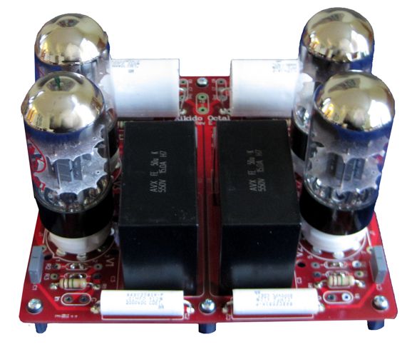
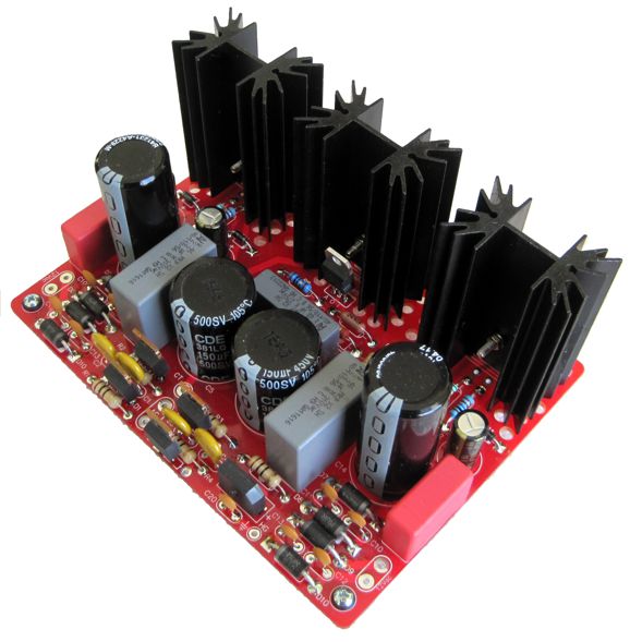
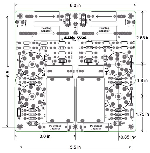
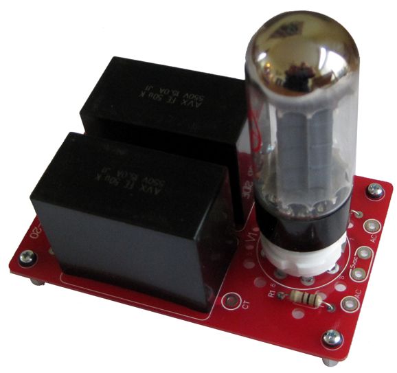
Aikido Octal Stereo Rev. E After bringing the Aikido noval stereo PCB into its E revision, where the high-voltage power supply capacitors are pure polypropylene, with no electrolytic capacitors, I was eager do the same to the Aikido octal stereo PCB; moreover, I set the PCB up just like noval PCB, where each channel gets its own separate heater power supply. I stuck to the same red solder mask and the PCBs are still 6in by 6in in size. The octal tubes are both close to each other and the large 50µF RC capacitors, so 6AS7 tubes cannot be used. I doubt that this failing will make much of a difference, as 99% will want to use 6SN7 tubes. On the other hand, 12SN7 and 12SX7 and 5692 tubes could be used, along with the 6H30pi in the octal envelope.
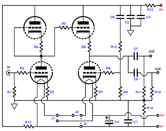
The two big black boxes each hold 50µF of polypropylene capacitor that is rated for up to 550V and 15A; each capacitor has for PCB-mount leads on its bottom. Obviously, they were not created with audio in mind, but some industrial application. Here is the schematic of one of the two Aikido line-stage amplifiers on the PCB.
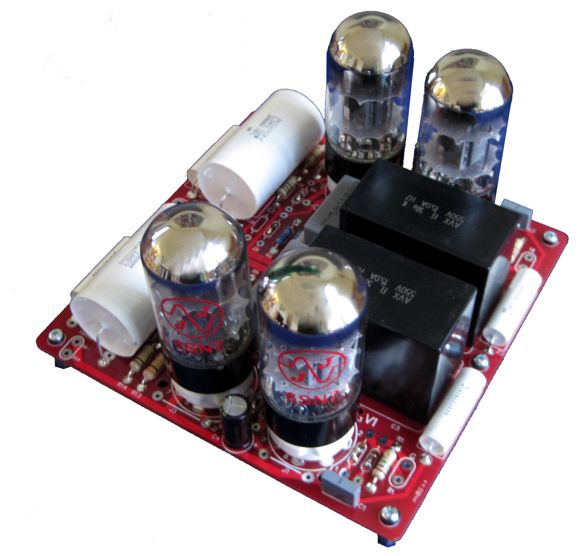
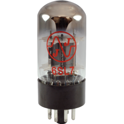
The old octal stereo PCB held over 150µF of RC capacitance per channel. This allowed us to get away with making an Aikido push-pull output stage, so that high-impedance headphones could be driven. But with only 50µF of RC capacitance per channel, this option no longer makes sense. The best workaround would be to use a low-winding ratio output transformer. For example, the primary could present a load impedance of 1,200 ohms, which would imply a winding ratio of 2:1 to a 300-ohm secondary; In addition, a low-impedance secondary tap could be added, which would allow the use of 32- to 50-ohm headphones, which implies a winding ratio of 6:1. With such an output transformer, a 10µF coupling capacitor would prove large enough to allow bandwidth below 20Hz. Wait a minute, John, many vintage tube power amplifiers only hold 40µF of power supply capacitance. True enough, but they also work into 5k primary impedances, not 32 ohms. In the photo above, we see four of the new JJ 6SN7 tubes. I had bought two of these tubes last year and I was pleased with their performance, so I order a second pair. How do they sound? Problems. One tube lit up bright, as if air had invaded the vacuum, and made horrific crackling sounds. I replaced it with an NOS Sylvania 6SN7 and all was well. This episode got me thinking about those poor individuals who do not own a huge stash of tubes. In other words, would such an audiophile not realize that the tube was bad and assume that the circuitry was at fault, thereby possibly making things worse or at least wasting his time? Probably. (The first rule is to swap tubes between channels. If the problem follows the swap, then the problem lies with the tubes. If the problem remained in the same channel, the problem will be found in the circuitry. I would first inspect both sides of the PCB, looking for bad solder joints and breaks in the symmetry.) Well, what do I think about the three JJ 6SN7 tubes? So far, they sound more like the NOS 6SN7 than anyone would want to admit in public. (What's the point of paying up to $100 for an NOS tube if the $15 current production tube sounds close enough? Well, one answer might be that the NOS tube will probably far out last the new tube.) Until I get a replacement for the bad JJ tube, a true shootout cannot be held. By the way, JJ has also come out with a 6SL7 and I bought a pair, but I haven't had a chance to give it a listen yet.
A friend once explained to me that whenever a fast-food restaurant, such as McDonald's, comes out with a new sandwich, be sure try it in the first few weeks of its introduction, as they make a big effort to do it right, as that first bite will leave a lasting imprint on your taste-buds, which will linger long past the sandwiches inevitable decline into mediocrity. With tubes, however, the opposite is probably closer to the typical experience, with the first shipment of tubes being the worst, as not all the bugs will be known yet and workarounds have yet to be implemented.
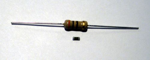
I used the PS-21 to power the new Rev E octal PCB. I suppose that I could have used a PS-15 instead, but I was keen to do a small and fair shootout between the Aikido noval Rev. E PCB, which held 12AU7 and ECC99 tubes. So which version won? I preferred the sound of the octal Rev E, but then I might have wanted to prefer the sound of the octals. In addition, the fight was not entirely fair, as I used a new type of resistor on the octal build, MELF resistors. MELF stands for Metal Electrode Leadless Face. (If you thought that the "M" stood for mother, you have a dirty mind.)
Basically, the MELF is a resistor with no leads that was designed with surface-mount applications in mind. I could not locate any large MELF resistors in the values I needed, so I settled for tiny, extremely tiny ones, which were vastly smaller than a grain of rice. I am an old pro when It comes to soldering, as I am sure that I have passed my 1,000,000 solder joint. Well, they were dang hard to solder in place. The secret I found was to use toothpicks and popsicle sticks to hold them in place. I have read that these are the definitive resistor and that audiophiles should rejoice that they finally have got a break from high-tech. As I put it 17 years ago:
We will see how well the MELF fairs in audio land. From a conceptual standpoint, I cannot see why losing leads would make such a big difference. The end-caps are still made from steel; the resistive material is still spiral-cut metal-film. In contrast, a bulk-foil resistor uses a radically different construction. I only used the tiny MELF as grid-stopper and cathode resistors. So far, however, I am pleased with them. What is needed is an intelligent test. Now some would argue that anyone dares to use the word "intelligent" in anything but a knowing, winking, ironic way betrays a want of intelligence.* Be that as it may, I wish we held more experiments in audio. Here is how most would test a new resistor type: solder two, one per channel, in some portion of a circuit, say the cartridge loading resistor or the current-to-voltage resistor in a DAC or the negative feedback resistor in a power amplifier, and then listen to the results. Well, what's wrong with that? Here is one possibility: one resistor skews the sound in a euphonic fashion, which we all find pleasing, but replacing all 100 resistors with this type results in blurred mess. Here is an analogy: when making wine, having one ladybug fall into a few gallons of wine makes for an interesting a green bell pepper flavor; three ladybugs and you might as well pour the wine down the drain. Here is another analogy: you step out into an overly bright and glare-filled day, so you put on your sunglasses and everything looks so much better. Now, would placing ten pairs of sunglasses atop each other provide a tenfold improvement?
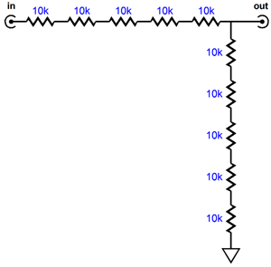
What I have done in the past, was make a fixed, stereo attenuator with say 20 resistors per channel. I then compare the sound coming out to another type of 20 resistors in the same attenuator configuration. See post 304 for more details. With some resistors costing over $25 each, such a test can get expensive, which is why I recommend that an audio club perform the test, so the cost can be spread out across 30 members. One secret is to have everyone silently and secretly and anonymously make his evaluations, as a few dominating personalities can sway the group. The worst thing that you can do is to ask for a show of hands. Another important test requirement is that at least two test music tracks be used. One should showcase a cleanly recorded single acoustic instrument, such as guitar or saxophone or cello; the other test track should contain a complex array of instruments or massed voices. Why? I have found that overly ripe-sounding electronic parts provide for a lovely reproduction of the solo voice or instrument, but take away from the reproduction of many voices and instruments.
The new Aikido octal Rev. E PCB and kit are available now at the GlassWare-Yahoo store.
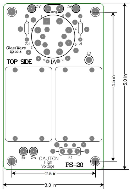
PS-20 Tube Rectifier Power supply If you plan on building a tube-based power amplifier or robust line-stage amplifier, and if you desire tube rectification, this is the the power supply kit to get.
The new PS-20 tube-rectified power supply kits are available now at the GlassWare-Yahoo store.
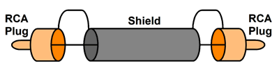
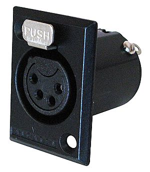
Fancy Interconnects Normally, an interconnect's shield is simply grounded at both ends and it is the ground wire.
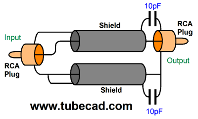
We can get fancy by using two wires inside the shield and only ground one end of the shield, usually at the input side.
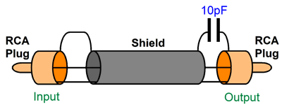
The 10pF capacitor is used to AC terminate the shield at ultra-high frequencies, lest the screen act as an antenna. We can get even fancier by using two shields, one for the hot wire and one for the ground wire.
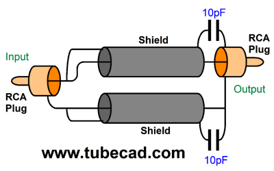
Thirty years ago, in Silicon Valley, we referred to this arrangement shown above as shotgun cable, as in double-barrel shotguns. From this setup, it is a small step to arrive at a actively driven shield for the hot wire.
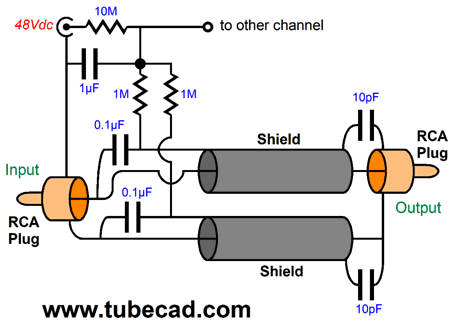
The shield sees 100% of the signal that the hot wire does, so the capacitance between the hot wire and the shield is effectively neutralized, as the two never see a voltage difference. The ground wire is also shielded and its shield is simply grounded. We can get even fancier still by applying a polarizing voltage to both shields, as shown below. Now, a DC voltage differential exists between shield and inner wire, but in AC terms, no AC voltage exists.
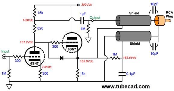
An external voltage source is used, which could be four A27 batteries or a switcher wallart power supply. Switcher power supplies put out a lot of ripple, high-frequency ripple at that, usually about 0.1Vac to 0.5Vac, which we do not want. The RC filter formed by the 10M resistor and 1µF will greatly attenuate the ripple, as will the intrinsic RC filter formed by the 1M and 0.1µF coupling capacitors. In fact, if high-quality film capacitors are used throughout, we could disconnect the external voltage source and let the established charge slowly fade away. (To fully charge up the 1µF capacitor will take about one minute; to have fully self discharge might take a few hours—if not a day. I just performed a test on the 1µF CDE coupling capacitors that I like so much; it held its charge for over 12 hours. Nice!) So far, the hot-wire shield has been actively driven by the connection to the hot wire. Well, what if we designed an active circuit to drive the shield separately? Here is one possibility.
The input 6SN7 drives the coupling capacitor and the hot wire, but the cathode follower drives the hot-wire's shield. Note how the cathode follower's input sees a slightly higher input signal than the hot wire does. What is going on here? No cathode follower can deliver 100% unity-gain, so we must give it an inversely higher input signal, so that its output can match that seen by the hot wire. For example, if the cathode follower realizes a gain of 0.95, then its grid must see 1.053Vac of signal to deliver 1Vac at its cathode. By the way, the assumption behind the above circuit is that the power amplifier's input impedance is 47k. If it is a low 20k, then 820-ohm resistor should be replaced by a 620-ohm resistor. (Yes, a rotary switch could be used that would allow fine tuning for different load impedances.) Shouldn't the hot wire get the cathode follower's low output impedance connection instead? I am inclined to think not. As I mentioned in my last post, the charging and discharging of capacitance requires current. In this setup, the hot wire only "sees" the input capacitance of the power amplifier's input stage, as the shield is driven with the same amplitude of output signal. Both the grounded-cathode amplifier and cathode follower draw the same idle current, so both can deliver the same amount of output current swing. But by giving the shield the lower output impedance connection, we allow the shield to better perform its task of shielding the hot wire from external interference. Since the hot-wire's shield come pre-polarized, we can tap off some of its high-voltage to polarize the ground wire's shield, which we do through the 1M resistor, while the 0.1µF capacitor to ground shunts away the AC signal. (If you want, you can use a larger-valued capacitor.) Of course, we cannot use RCA plugs at each end of this interconnect. One workaround is to just hardwire the input side of the interconnect. (While a college student, I got rid off all the RCA jacks and plugs by hard-wiring all my audio gear together, phono stage to line-stage amplifier to power amplifier to speakers, with the only non-soldered signal contacts existing between the phono cartridge and the tonearm. I even soldered the speaker cable right on to the output transistors. How did it sound? Fabulous. But moving any of it was a nightmare. Let no audiophile accuse me of being anything less than hardcore, for I have paid my dues.) Another workaround would be to use a four-pin XLR connector on the line-stage amplifier side and an RCA plug on the other end of the interconnect. I like this second workaround best, as it would allow for much experimentation.
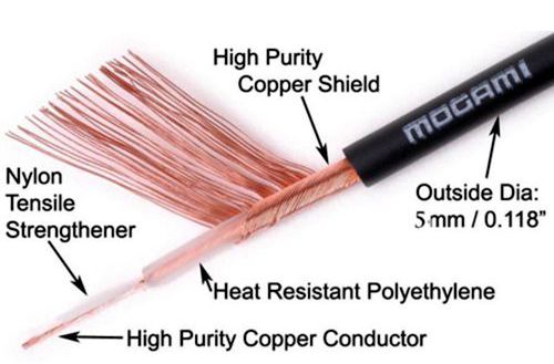
An added feature to this arrangement would be the constant-current-draw aspect of the design, wherein the grounded-cathode amplifier and cathode follower draw the same idle current and experience the same anti-phase AC current swings, resulting in a constant-current-draw from the power supply. Which greatly unloads the power supply and prevents signal-induced perturbations in the power-supply voltage. What cable should be used? Any high-quality coaxial cable with a pure-copper hot wire and good shield should work well. Just make sure that copper-plated steel wire is not used for the hot wire.
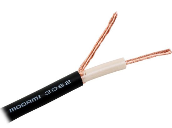
I remember being pleased with Mogami W2524 instrument cable, which costs less than $2 a foot and is easy to work with, as it is so supple. Another possibility is the Mogami W3082 shielded speaker cable. What if you do not want a new line-stage amplifier, just fancy interconnects? Well, we can use an external tube circuit to drive the hot-wire's shield. Here is one possibility.
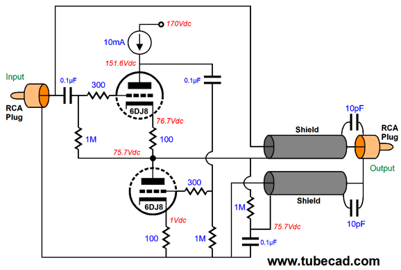
A White cathode follower is used with a constant-current source plate load, which will allow the White cathode follower develop a closer approximation to unity gain and shield the triodes from the power-supply noise. In this configuration, the top triode effectively draws a constant current, while the bottom triode undergoes all the AC signal current variations. In other words, this circuit function much closer to being a single-ended design than a push-pull one. The 0.1µF coupling capacitor is effectively much larger in value, as the 1M grid resistor is effectively bootstrapped by the output signal. Once again, the ground wire's shield is polarized and it steals its DC voltage from the White cathode follower's output. The 6DJ8 runs under the relatively low B+ voltage of 170Vdc, with a cathode-to-plate voltage of less than 75V. The constant-current source can be made from an LM334, with a shunting 35V zener protection diode. Or we could use something fancier. Hell, we can even use the following circuit, which forgoes the use of a constant-current source altogether.
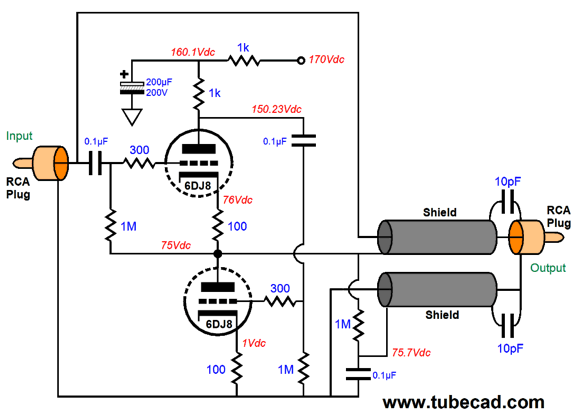
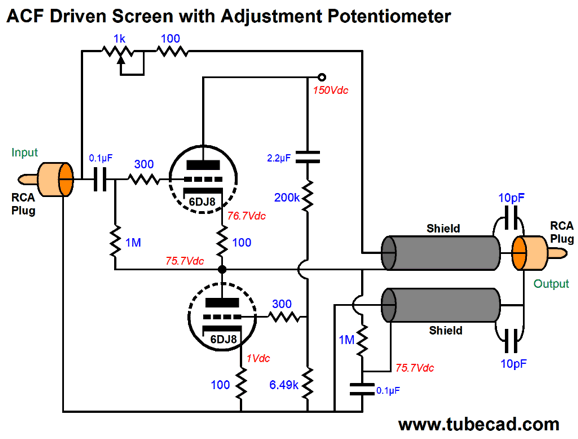
The 1k resistor and 200µF capacitor forms a low-pass filter that exhibits a -3dB frequency of less than one Hertz. The 1k plate resistor is far from being mistaken for a constant-current source, but it is nonetheless quite high in this application. Another possibility is to use an ACF circuit instead.
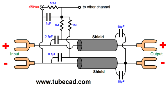
The power-supply noise is nulled through the bottom triode. The 100-ohm resistor and 1k potentiometer are used to provoke an attenuation of the signal travelling through the hot wire so that it matches the output of the ACF. If we do not want to deal with vacuum tubes and high-voltages, we could opt for a solid-state solution, which could be left on all day and night.
Once again, a 48Vdc switcher wallwart is used. The high-voltage OpAmp's output is not centered at 24Vdc, but at 42V, which will lend some polarized wire mojo to the effort. I would use an OPA551, as it is unity-gain stable and can withstand 60V across its power-supply pins. In addition, it can deliver up to 200mA of output current. Two OpAmps and a few resistors and capacitors could easily fit in a small metal box, which would sport two RCA-plug terminated cables for receiving the input signal and two RCA-plug terminated output cables for connecting to the power amplifier. Note that the OpAmp only drives the hot-wire's shield, not the hot wire.
If done up in a fancy enough of box, I could readily see some high-end cable company selling this arrangement with an easy $1,000 to $3,000 price-tag. Could we apply this same arrangement to speaker cables? Yes. Since Mogami W3082 shielded speaker cable is readily available, I would give it a try.
The big difference, however, is that where an interconnect only sees a few volts of signal, a speaker cable can see many tens of volts. For example, a 200W amplifier swings 56Vpk, so the screen would have to see the same voltage swing. This brings us back to the realm of tubes. One possibility, however, is the high-voltage OpAmp, the LTC6090, that can withstand a power supply voltage differential of 140V. I would first try the following:
This setup lets the power amplifier drive the shield on the hot wire. I would first listen with no polarizing voltage; then after a few albums, I would plug the 48V wallwart in in and listen again. The terminating 10pF capacitors are probably far to small in this application, so 100pF should be tried instead. Another possible arrangement would be to terminate these capacitors into the house ground. Quite a few audiophiles have told me that thier speakers sound much better with the driver's metal basket grounded to the house ground. So many ideas, so little time.
Music Recommendation: La Segunda, Será Una Noche
Although English is probably not his native language (I cleaned it up a bit), he does get his point across. The M & A that the reviewer mentions is the recording label. Do check out their web page devoted to this album. The sound is amazing on this CD, which explains why used copies go for $71.08 each. But the music is also amazing. I was so taken by some of the songs that I had to look up the lyrics in Spanish. The music is Tango, which started out as purely instrumental, but singing was soon added. In fact, Tango lyrics are closer to good poetry than to just pop song banalities. One example is the song, Nunca Tuvo Novio:
And in the original Spanish:
Fortunately, Será Una Noche is available at Tidal. Do not wait, just listen to it, from beginning to end—then repeat. This album is also available as a 24bit/176.4 kHz Hi-Rez DVD-ROM and as a two-LP set.
//JRB
*"Intelligent" "But he doesn't have a high IQ. He told me that his IQ was only a little over 120, which puts him squarely in the average at this university," I explained. My friend cried out, "What! Just 120? No wonder he believes in IQ. If had only an IQ of 120, I, too, would believe in IQ."
User Guides for GlassWare Software Since I am still getting e-mail asking how to buy these GlassWare software programs:
For those of you who still have old computers running Windows XP (32-bit) or any other Windows 32-bit OS, I have setup the download availability of my old old standards: Tube CAD, SE Amp CAD, and Audio Gadgets. The downloads are at the GlassWare-Yahoo store and the price is only $9.95 for each program. http://glass-ware.stores.yahoo.net/adsoffromgla.html So many have asked that I had to do it. WARNING: THESE THREE PROGRAMS WILL NOT RUN UNDER VISTA 64-Bit or WINDOWS 7 & 8 or any other 64-bit OS. One day, I do plan on remaking all of these programs into 64-bit versions, but it will be a huge ordeal, as programming requires vast chunks of noise-free time, something very rare with children running about. Ideally, I would love to come out with versions that run on iPads and Android-OS tablets.
//JRB |
John Says Thanks the Special 68 Only those who have produced a technical white paper or written an article on electronics know just how much time and effort is required to produce one of my posts, as novel circuits must be created, SPICE simulations must be run, schematics must be drawn, and thousands of words must be written.
If you have been reading my posts, you know that my lifetime goal is reaching post number one thousand. I have 577 more to go. My second goal is to gather 1,000 patrons. I have 932 patrons to go.
The Tube CAD Journal's first companion program, TCJ Filter Design lets you design a filter or crossover (passive, OpAmp or tube) without having to check out thick textbooks from the library and without having to breakout the scientific calculator. This program's goal is to provide a quick and easy display not only of the frequency response, but also of the resistor and capacitor values for a passive and active filters and crossovers. TCJ Filter Design is easy to use, but not lightweight, holding over 60 different filter topologies and up to four filter alignments: While the program's main concern is active filters, solid-state and tube, it also does passive filters. In fact, it can be used to calculate passive crossovers for use with speakers by entering 8 ohms as the terminating resistance. Click on the image below to see the full screen capture.
Tube crossovers are a major part of this program; both buffered and un-buffered tube based filters along with mono-polar and bipolar power supply topologies are covered. Available on a CD-ROM and a downloadable version (4 Megabytes). |
||


| www.tubecad.com Copyright © 1999-2018 GlassWare All Rights Reserved |