| John Broskie's Guide to Tube Circuit Analysis & Design |
25 December 2016 Post 406
Merry Christmas
Since I hold such warm memories of the warmly glowing tubes, why don't I repeat this coolest-warmest Christmas tree every year? Other than wife acceptance factor, which in this case is next to nil, the heat dissipated by the tube heaters was about 75W. A better approach would be to solder inside the tube sockets an amber-colored LED, which would shine up into noval tubes, which hold clear bases and are much lighter than their big brother octals. In addition, the tubes would not wear out (nor incur the dreaded triode sleeping disease, the result of running hot heaters with no cathode current flow for long times). An even better solution might be for some enterprising fellow to have faux tubes made in China with LEDs built in, as the tube sockets are heavy and expensive. One hundred faux tubes could wrap around a large tree and draw very little current. At the tree's top, we could place a warmly glowing faux 300B.
Special Thanks to the Special 60
If you have been reading my posts, you know that my lifetime goal is reaching post number one thousand. I have 594 more to go. My second goal is to gather 1,000 patrons. I have 940 patrons to go. If you enjoyed reading this post from me for the last 18 years, then you might consider becoming one of my patrons at Patreon.com. It would make a big difference to me. Thanks.
Bridge Amplifiers
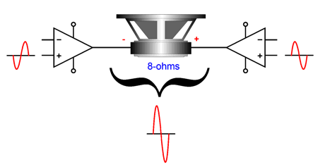
The bridge configuration also allows us to use a mono-polar power supply and not have to supply an output coupling capacitor, as the loudspeaker sees no differential DC voltage, although both power amplifier might present 24Vdc at their outputs at idle. For this reason, the bridge amplifier is often used in cars and TVs. Moreover, the bridge configuration effectively doubles the amplifier's slew rate and often improves the power amplifier's PSRR, as common-mode noises are ignored by the loudspeaker. Remember, the speaker is an intrinsically differential device, which is only sensitive to differential signals, ignoring common or shared signals. In other words, the two amplifiers might leak much of the power-supply noise at their outputs, but as long as the noise is equal and in phase, the speaker driver ignores it.
The bridge configuration gives us twice the gain of its individual power amplifiers.
All is not butterflies and rainbows, however, as each of the two power amplifiers effectively see half of the load impedance, so an 8-ohm loudspeaker appears as a 4-ohm speaker to each amplifier. But getting more output current flow from solid-state devices is not that big a deal.
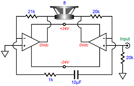
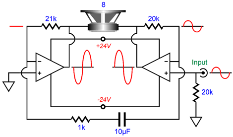
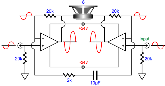
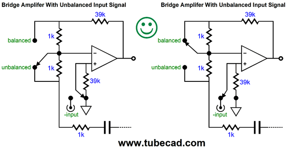
A bridge amplifier can be driven by either unbalanced, as shown above; or with balanced input signals, as shown below.
Note the small change in negative feedback resistor values between the two circuits. When a bridge amplifier is designed for an unbalanced signal, the amplifier on the right functions as a non-inverting amplifier, while the amplifier on the left, in contrast, operates as an inverting amplifier, which derives its input signal from the feedback loop of the right amplifier. An alternative approach taps the inverting amplifier's input signal directly from the input signal.
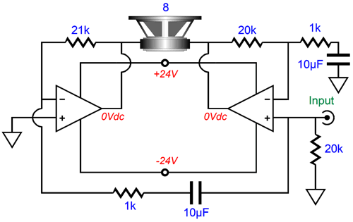
This approach works well with OpAmps, but not so well with power amplifiers, particularly chip amplifiers, such as the LM3886, as these amplifiers are sensitive the main negative feedback resistor's value, preferring lower values over higher ones. So, if we use a 21k negative feedback resistor on the inverting amplifier, the input resistor will be 1k, which is a dang-low input impedance. In addition, two DC-blocking capacitors will be needed: one to terminate the right amplifier's negative feedback resistor and one at the left amplifier's input resistor. Without these capacitors, the amplifiers will amplify DC offsets. (I would add an input capacitor to the right amplifier's input, bringing the cap count up to three.) Is that a problem with bridge amplifier, as the resulting two amplified DC offsets will be differentialy ignored? Sadly, they won't, as the DC offsets will be out of phase with each other, so they will add. Adding a toggle switch would allow us to choose between unbalanced and balanced input signals. The following works well, but only if the switch isn't thrown while the amplifier is on. We only have to make an adjustment to the left side of the circuit.
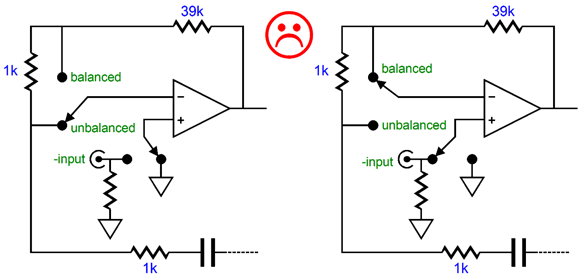
A safer setup is the following, as the left applier does not lose contact with ground as the switch moves from one position to the other.
If you are wondering why I am going over bridge-amplifier basics, the answer is that I want to move on to electrostatic power amplifiers, which would have to be built into the electrostatic loudspeaker. (Would you feel safe with speaker wires running across your floor that held a thousand-volt voltage swings?) Well, a bridge amplifier could prove useful in this application, as it effectively doubles the possible output voltage swings from the amplifiers; and an electrostatic step-up transformer still need big input voltage swings.
To get an idea of big of output voltage swings we could get from a bridge-amplifier configuration, let's consider a single 200W solid-state power amplifier, which must swing 56.6V of peak voltage to deliver 200W into an 8-ohm load. In the bridge amplifier configuration, this peak voltage swing doubles to 113Vpk, which would yield 800W into 8-ohms. Of course, an electrostatic panel is not a resistive load; instead, it is a reactive load whose impedance depends on the frequency, presenting zero ohms at DC and close to a dead short at ultra-high frequencies. I once knew a fellow who owned large electrostatic panels and two 500W solid-state power amplifiers. He lived in a Victorian apartment building, high up, in a building filled with old, thin AC wire. The result was that when the music delivered loud cymbal clashes, his lights dimmed throughout his apartment.
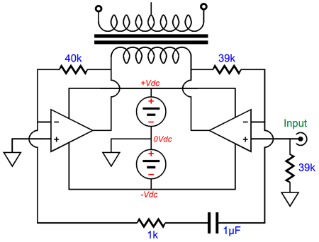
Returning to the 113V of peak differential voltage swing, with a step-up transformer that offers a 1:10 winding ratio, we would get 1,130V swings at the electrostatic stators; with a 1:20 winding ratio, 2,260V swings. By the way, a tube-amplifier output transformer with a primary impedance of 3,200 holds a winding ratio of 20:1. A 200W solid-state power amplifier usually holds power-supply rail voltages of +/-60V to +/-70V. but we could easily use a monopolar power supply in a bridge amplifier. in other words, we could use a single power supply voltage between +120V to +140V.
What about ground? We can create a faux ground with a two-resistor voltage divider and added capacitor.
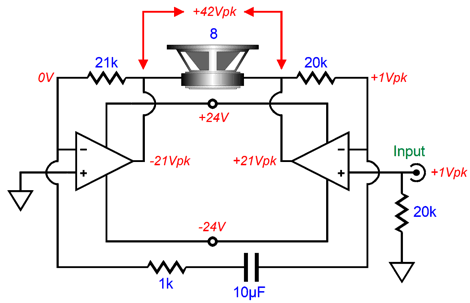
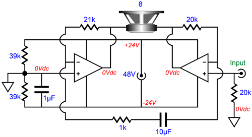
Most amplifiers present a poorer PSRR from their negative power-supply connection than from their positive connection—but not always. Thus, it's best to look at the amplifier's data sheet or measure the two directly. If the positive terminal presents the weaker PSRR, then the capacitor should shunt the top resistor, not the bottom one. Of course, we can locate the power supply externally from the loudspeaker. One possibility is to use a switcher power supply, either the wallwart or desktop style. Unfortunately, these switching power supplies usually top out at 48Vdc. Still, with just 48V, we could drive an 8-ohm woofer to 110W in a bridge-amplifier configuration.
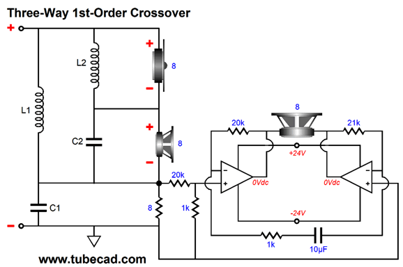
Both amplifiers swing 21V peak volts, which equals 42Vpk across the woofer, which in turn equals 110W into 8 ohms. The formula for wattage is: Watts = V² / 2Rload By the way, I would like to build a loudspeaker designed to work with flea-power single-ended tube power amplifiers, which might top out at 16W. The secret would be to use high-efficiency midranges and tweeters, say 94dB types, with a powered 87dB woofer.
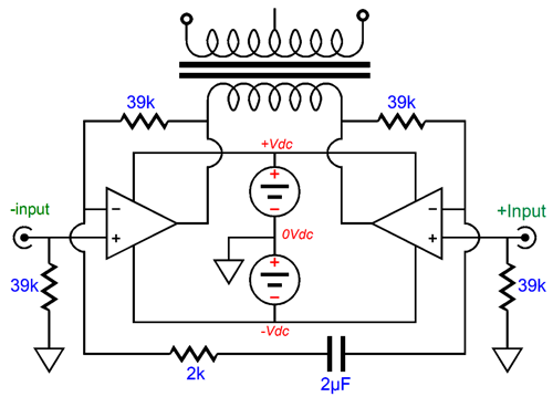
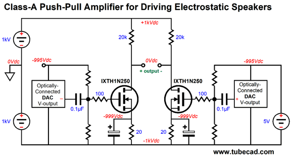
The flea-power amplifier sees a constant 8-ohm load and the woofer sees twice the flea-power amplifier output voltage. Thus, the woofer sees four times the power that the midrange and tweeter see, which results in a +6dB boost in SPL, which brings the woofer in line with the midrange and tweeter. A 24V switcher power supply could power the internal bridge amplifiers with voltage to spare, as each amplifier need only swing up to +/-16Vpk. The simple first-order speaker crossover feeds the internal bridge amplifiers their input signal and maintains a constant 8-ohm load for the small tube amplifier. Yes, the 8-ohm resistor just gets warm and does not make any sound; still, it allows the series crossover to work and it keeps the speaker's load impedance at 8 ohms. The two-resistor voltage divider across the 8-ohm resistor reduces the input signal my 1/21, so the bridge amplifier can still be set for a gain of 21 (42 differentially). Few of the power chip amplifiers are unity-gain-stable and this set up will keep them happy. Many high-end loudspeakers, such as the Vandersteen Audio's Model 5A (one of my favorite loudspeakers, by the way), already sport internal power amplifiers that drive their internal subwoofer. This proposed flea-powered loudspeaker would only differ in that no subwoofer is used and the woofer goes up to 400Hz. Of course, we could build a more robust version that handled twice the tube amplifier output voltage, say 32Vpk, which would equal 64W into 8-ohm loudspeakers. Here, the midrange and tweeter might only offer 91dB for 1W of input power and the woofer might span between bridge amplifiers that ran off of an internal power supply, which could yield 200W for an 8-ohm woofer. Now the difference between 64W and 200W is not that big, as far as your ears are concerned. But this setup would allow an 85bB woofer to be used with the 91dB midrange and tweeter; in addition, the woofer might benefit from the solid-state power amplifier's lower output impedance and lower power bandwidth. Returning to driving electrostatic panels, we could build bridge amplifier with balanced inputs and an internal bipolar power supply, as in the following example.
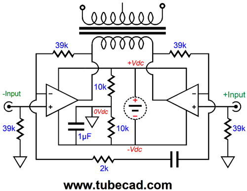
Or, we could retain the balanced inputs and use a monopolar power supply.
Alternatively, we could use unbalanced inputs and a bipolar power supply.
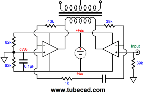
And, last, we could use unbalanced inputs and a mono-polar power supply.
Note the feedback resistor values used in all these examples.
Direct-Drive Electrostatic Amplifiers
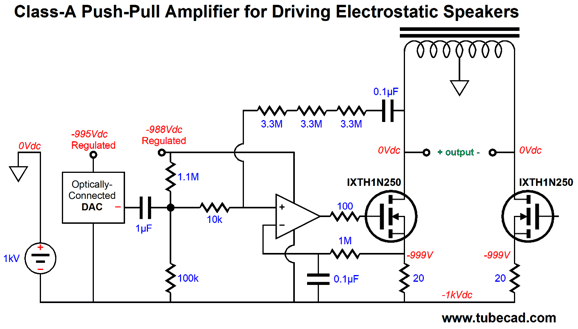
(As I look at the schematic now, I see that the 20-ohm source resistors should be bypassed by large-valued capacitors.) The theoretical limit to efficiency with inductive loading in a class-A amplifier is 50%. At the other extreme, we can replace the inductive loading with resistive load and be lucky to get 8% efficiency. On the other hand, electrostatic panels are not resistive loads, but reactive ones. At low frequencies, very little current will be required; at high frequencies, lots. As long as we either limit the panel capacitance or its high-frequency bandwidth, or both, we can probably get away with resistor loading. (This makes a good case for using a ribbon tweeter with our electrostatic panels.)
The optically-connected DAC puts out voltage, not current, so it can drive the MOSFETs gates. An optical connection is essential, as the DAC sits at -1,000Vdc. Depending on the DAC, the MOSFET's high input capacitance might prove difficult to drive directly. The workaround would be to use an intervening OpAmp.
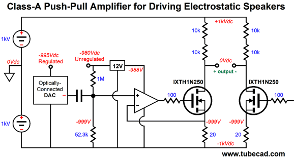
The OpAmp drives the MOSFET's gate and monitors its current flow by closing its negative feedback loop at the MOSFET's source. Note the subtlety of attaching the two-resistor voltage divider (1M & 52.3k resistors) to the unregulated -980V power-supply rail, not the regulated -988V rail. Why? The +/-1kV power-supply rails are not likely to be regulated, so their voltage will vary with the wall voltage variations; so, too, will the unregulated -980V power-supply rail. In other words, this arrangement keeps the output centered in spite of wall-voltage variations. A second subtlety was my replacing the single 20k load resistor with two 10k resistors in series. This was done for two reasons: the first is that these resistors will get plenty hot; the second is that resistor exhibit a high-voltage-induced distortion, so the more resistor we place in series the better. Note that the OpAmp's negative feedback does not terminate into the MOSFET's drain, but its source; this makes the amplifier a fundamentally current-out design, although its output will swing many hundreds of volts, due to the resistor loading functioning as a current-to-voltage converter. One result is that the drain output impedance is near infinite and the difference output impedance will equal 40k. If we do the math, we see that bandwidth out to 6kHz will force us to limit the load capacitance to 660pF, which isn't a lot. If we attached the negative feedback loop to the drain, we get a vastly lower output impedance, but we will still be current limited by the load resistors. In other words, we can pull down much harder through the MOSFETs than we can push up through the resistors. In short, I don't think this is the way to go, save for an electrostatic bass panel that only went up to 500Hz or so—or a scaled down version for driving electrostatic headphones. There will be much more to come on this topic in my next post, as we will move on to push-pull direct-drive designs.
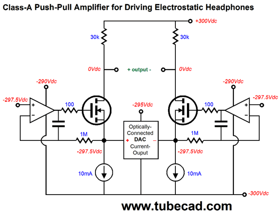
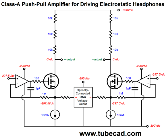
Direct-Drive for Electrostatic Headphones
Appearances to the contrary, the OpAmps do not drive the MOSFETs; instead, they merely set the source voltages to a fixed value. The current-out DAC feeds it output current into the MOSFET source, causing the change in current drawn through the MOSFET to alter, which in turn causes the voltage drop across the 30k drain resistors to alter, creating the output voltage for the electrostatic headphones. If we want to see the drain voltage drop by 180V, then its drain resistor must see a 6mA increase in current conduction. So far so good, but DACs usually put out only 2mA of current. The workaround is to place several in parallel. The two constant-current sources set the idle current and could be replaced by resistors. Indeed, the MOSFETs could be replaced by triodes as well.
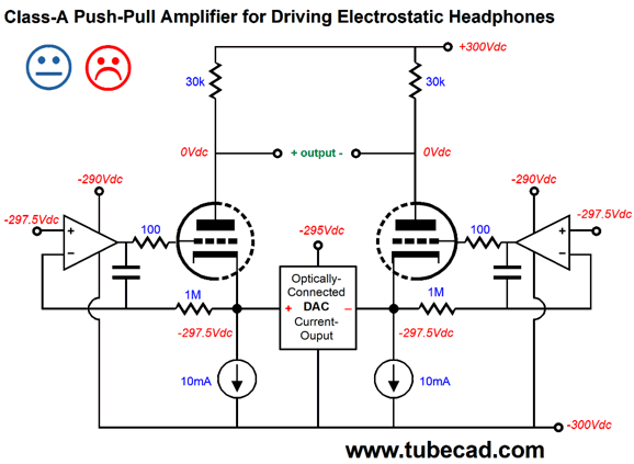
The problem with just replacing the MOSFETs with triodes is the high cathode impedance, which the current-out DAC will not like. John, have you lost your mind? A triode's cathode always presents a low impedance. True enough, except when it isn't true. The cathode's impedance depends on the rest of the circuit. One triode floating in the middle of your living room has a cathode impedance of close to infinity, which it would reach if it were not for the capacitance between the cathode and other objects in the room. With a grounded-grid amplifier, the impedance is equal to (Ra + rp) / (mu + 1), assuming a constant-current source cathode biasing. If a cathode resistor is used instead, then its resistance must be placed in parallel with the previous result. If we used a JJ ECC99 triode with an rp of 2300 ohms and a mu of 22, the resulting cathode impedance would equal (30k + 2.3k) / (22 + 1) or 1400 ohms. The only current-out DAC that I can think of that would be happy with this high load impedance is the ESS DAC, as it straddles between being a voltage-out and a current-out DAC.
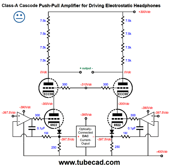
By cascoding we can get a much lower cathode impedance, as the 1400 ohms will add to the 6922's low rp and the sum will be divided by 34, and this result will be in parallel with the 250-ohm cathode resistor, resulting in an impedance of less than 100 ohms. The two DC servo loops keep the 6922's cathodes at the correct voltage for the DAC. The two diodes were not added to confuse, although I am sure that their presence will confuse. The DC servo must be able to put out a low-enough voltage to set the 6922's idle current to 10mA. By adding the diodes, we gain about 0.7V of voltage headroom for the DC servos. Why no happy face? Since several DACs must be placed in parallel to get enough current swing to the drive the amplifier's outputs, the just below 100-ohms input impedance will effectively be multiplied by the number of DACs in parallel. This brings us to the following compromise:
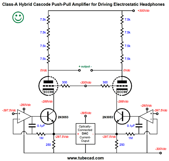
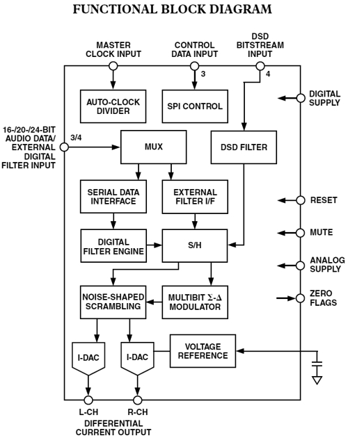
The NPN transistors are in cascode with the ECC99 triodes. The emitter input impedance is super low, which will make the DACs much happier and the triodes shield the low-voltage transistors from the high voltages. Thus, the happy face. By the way, an interesting DAC is the AD1955, which is a balanced, stereo, current-out type that sinks an idle current of 3.24mA per output.
Here is what the data sheet says:
By using one AD1955 DACs per channel we would end up using two DACs outputs in parallel per phase leg and the two outputs tied together would draw 6.48mA of current, so the constant-current source below need only draw 10mA – 6.48mA or 3.52mA of current. Each output can swing up bit over 4mA, so 8.64mA of current swing would flow through the 30k drain resistor, resulting in a voltage swing of 259.2Vpk. Not bad. What if your favorite DAC is a voltage-out type? Well, you could use the following circuit.
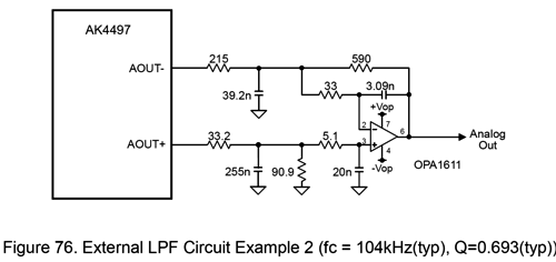
Once again, the DAC drives the MOSFET sources, but this time through a resistor, which becomes the I-to-V converter. If you are worried about the internal-to-the-DAC OpAmp not being up to the task of swinging big output currents, you are not alone. At the same time, I take a lot of comfort from the following schematic from the AK4497 voltage-out DAC, a highly esteemed DAC.
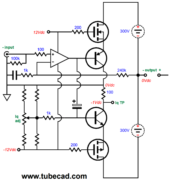
Note that the positive output must drive a 124.1-ohm load, while the inverted output must drive a 215-ohm load. Even at only 1.4Vpk of voltage swing, those are tough loads. If we set the series resistor value to 150 ohms, the gain would equal 30k/150 or 200, which against the 1.4V output swings would yield 280Vpk swings per phase leg or 560Vpk-to-pk swings differentially upon the stators. Also, not bad. Okay, what if you don't want the DAC to sit at -300V? What if, in fact, you do not want any DAC anywhere near your pure-analog system? Well, the following design is one answer and it also will help you prepare for my next post.
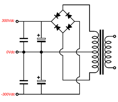
The inputs are at ground level and require a balanced input signal. (An easy workaround is available for those who only run unbalanced signals; just look at the above bridge-amplifier circuits.) A stereo electrostatic headphone amplifier will require four of the above circuits, two per channel. The dashed circles represent floating power supplies, i.e. power supplies that are not directly grounded. The two power MOSFETs will swing the floating power supply up and down 250 volts, so the power supply cannot be grounded. Fortunately, a bipolar, high-voltage power supply is not hard to make.
Four of the above circuits will be needed, so four center-tapped secondaries will be needed. //JRB
User Guides for GlassWare Software Since I am still getting e-mail asking how to buy these GlassWare software programs:
For those of you who still have old computers running Windows XP (32-bit) or any other Windows 32-bit OS, I have setup the download availability of my old old standards: Tube CAD, SE Amp CAD, and Audio Gadgets. The downloads are at the GlassWare-Yahoo store and the price is only $9.95 for each program. http://glass-ware.stores.yahoo.net/adsoffromgla.html So many have asked that I had to do it. WARNING: THESE THREE PROGRAMS WILL NOT RUN UNDER VISTA 64-Bit or WINDOWS 7 & 8 or any other 64-bit OS. One day, I do plan on remaking all of these programs into 64-bit versions, but it will be a huge ordeal, as programming requires vast chunks of noise-free time, something very rare with children running about. Ideally, I would love to come out with versions that run on iPads and Android-OS tablets.
//JRB |
Kit User Guide PDFs
And
High-quality, double-sided, extra thick, 2-oz traces, plated-through holes, dual sets of resistor pads and pads for two coupling capacitors. Stereo and mono, octal and 9-pin printed circuit boards available.
Designed by John Broskie & Made in USA Aikido PCBs for as little as $24 http://glass-ware.stores.yahoo.net/
The Tube CAD Journal's first companion program, TCJ Filter Design lets you design a filter or crossover (passive, OpAmp or tube) without having to check out thick textbooks from the library and without having to breakout the scientific calculator. This program's goal is to provide a quick and easy display not only of the frequency response, but also of the resistor and capacitor values for a passive and active filters and crossovers. TCJ Filter Design is easy to use, but not lightweight, holding over 60 different filter topologies and up to four filter alignments: While the program's main concern is active filters, solid-state and tube, it also does passive filters. In fact, it can be used to calculate passive crossovers for use with speakers by entering 8 ohms as the terminating resistance. Click on the image below to see the full screen capture.
Tube crossovers are a major part of this program; both buffered and un-buffered tube based filters along with mono-polar and bipolar power supply topologies are covered. Available on a CD-ROM and a downloadable version (4 Megabytes). |
||


| www.tubecad.com Copyright © 1999-2017 GlassWare All Rights Reserved |