| John Broskie's Guide to Tube Circuit Analysis & Design |
23 September 2016
Rocks
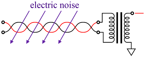
The obvious advantage balanced signals offer is that shielding is seldom required. Telephone systems run miles and miles of twisted, unshielded balanced wires. These wires do get infected with electrical noise, exposed as they are to an electrically turbulent environment, but remain noise-free.
Do not just blame man, as the Sun blares, discharges, and spews a torrent of electromagnetic radiation at us, which just might explain why listening to our systems at night is so much more pleasant than listening at noon. Now try to imagine how fine one of Vinnie Rossi all-battery-powered systems would sound at 1am during a power outage!
Thus, the magic of differential input stages and signal transformers: as long as both wires are equally contaminated, the added noise falls out of the equation, as only differences are passed on, while what is common is ignored.
Transformers to the Rescue
The above CCDA line-stage amplifier uses a signal-transformer at its input, which allows the CCDA to accept either balanced or unbalanced audio signals. The key point to observe here is that the RCA jacks must not be grounded to the enclosure or to a common ground point; in addition, the RCA jack ground lug must be switched in and out just as its hot center lug is. Failing to observe these two restrictions will undo much of the potential magic the signal-transformer has to offer.
In the above circuit, only unbalanced input signals can be accepted, no balanced signals. In fact, the signal-transformer loses its reason behind its inclusion, as it could just as easily be left out of the circuit. Moreover, the grounded RCA jacks means that the interconnects will define multiple ground connections to the signals sources, whereas the signal-transformer with the floating primary winding prevents any sharing of grounds between any of the signal sources and the line-stage amplifier ground. DC voltage isolation also has its advantages. For example, in the following circuit the CCDA is used with a bipolar power supply, which the signal-transformer makes possible.
Couldn't two coupling capacitors be used, one for the input signal hot and one for its ground? No, as the bipolar power supply is not noise-free; no power supply is. The ripple present on the negative power-supply rail will clash with the lack of ripple on the signal source's ground. (If the signal source truly floats, i.e. its ground is not attached to the house ground, the two coupling capacitors trick just might work. What about DACs that use switcher wallwart power supplies? Maybe? We would need to perform a test to see if the switcher's output was truly floating and not referenced to the wall socket voltages.) The big unanswered question is Why bother with the bipolar power supply? The answer is that the bipolar power supply creates a wonderful Aikido-esque result of the power-supply noise nulling at the CCDA's output.
Since the positive and negative rail ripple is equal in magnitude, but out of phase, the they null at the center of two equal resistance in series placed across the rails. So, the trick is to make the triode and its cathode resistor result in an impedance equal to the plate resistor value. Be sure to read blog post number 328, as it is filled with a much more detailed explanation and holds some super interesting circuits, such as the following, which achieves an Aikido-esque power-supply noise nulling at the CCDA's output with a mono-polar power supply.
Signal-transformers can also replace coupling capacitors. The following circuit uses both an input and output signal transformer.
Go ahead and scratch your head if you have to, as the two 1µF coupling capacitors seem so wrong. Why not just one coupling capacitor and why not terminate the output transformer's secondary to ground, the proper way, the way everybody else does it? Our goal is to achieve the wonderful Aikido-esque result of the power-supply noise nulling at the CCDA's output. The mono-polar power supply presents ripple at its B+ connection, which both the CCDA stage and the two coupling capacitors split in half. Since a signal-transformer is fundamentally a differential device, the equal power-supply noise at either end of its primary creates no differential signal for it to transfer to its secondary. Magic. Good magic. The two coupling capacitors are bigger than you might expect. Normally, when two 1µF capacitors are placed in series, we end up with half the capacitance, i.e. 0.5µF. Not so here, as the two coupling capacitors are effectively in parallel, not in series, so their capacitances add together, equaling 2µF. Note that each channel must get its own pair of coupling capacitors. Why? Signal transformers cannot tolerate any sustained DC current , which would be likely as the two CDDA outputs are not likely to be at the exact same DC voltage.
Balanced Null
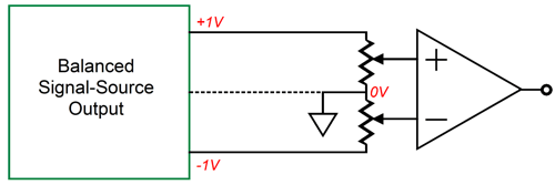
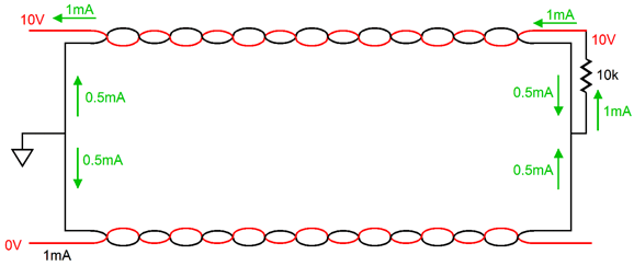
For example, a balanced pair of signals, say +1V and -1V, which can be either AC or DC voltages, are presented to a balanced line-stage amplifier, which holds a dual 10k volume-control potentiometer. The current flow equals 2V divided by 20k, or 0.1mA. At the line-stage amplifier’s ground, the two voltages null, so no current could flow from the line-stage amplifier’s ground to the balanced signal source’s ground, as no electric potential, no electromotive force exists between them.
In contrast, with unbalanced gear, the signal current must flow from one ground to the other. In a world of mono audio, this is not that big a deal, but in our stereo world it is. And when we add the problem of multiple connections to the house ground, the big deal gets bigger. Notice how, in the following illustration, the signal present in only one channel must take two paths back through the two ground leads, so the channel with no signal still experiences the unwanted current flow pass by.
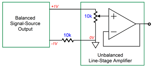
One workaround I have come up with is a setup that forces a null in the receiving audio equipment, although a balanced signal source was used with an unbalanced receiving device. Imagine an unbalanced line-stage amplifier with a 10k volume control potentiometer. Now add a balanced signal source and a special interconnect, which contains an extra 10k resistor. The result is that the non-inverting signal travels through the 10k potentiometer to the line-stage amplifier’s ground and then through the added 10k resistor within the interconnect and back to the balanced signal source, with the voltage null occurring in the line-stage amplifier. Even if the line-stage amplifier is a stereo design that shares a ground between channels, what signal that appears in one channel cannot bleed into the other channel.
Of course, the problem is that volume controls vary in ohmage, with 10k, 20k, 50k, 100k, and 250k being common. That is quite a spread, so one-size, or rather one-ohmage, interconnect won’t be possible. The interconnect, of course, could hold an array of resistors and a selector switch, but that would either be an advertising feature or a user hassle (or both).
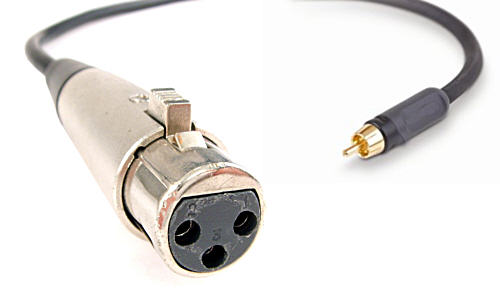
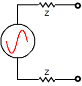
The biggest hassle, of course, would be the confusion resulting from having an interconnect terminated with a female XLR connector on one end and an RCA plug on the other end—and the need for a balanced signal source. From a theoretical standpoint, however, this arrangement violates the prime directive of balanced-signal transmission: equal impedances from both leads. In this setup, the positive lead offers very low impedance, while the negative lead presents at least 10k of resistance. Very unbalanced, indeed.
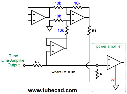
One workaround I came up with would work easily with OpAmps or discrete solid-state circuits, but could prove harder, but not impossible with vacuum tubes.
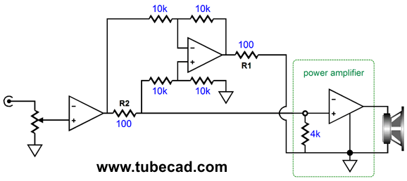
Faux Balance
The line-stage amplifier follows the potentiometer. The second OpAmp above the line-stage amplifier is a differential amplifier that monitors the current flow through the 100-ohm (R2) resistor. If no current flows through the 100-ohm resistor, no output voltage appears at the differential amplifier’s output. On the other hand, if 10mA flows through the 100-ohm resistor, then the differential amplifier’s output will be -1V. Let me now use part values that will make the voltage relationships clearer.
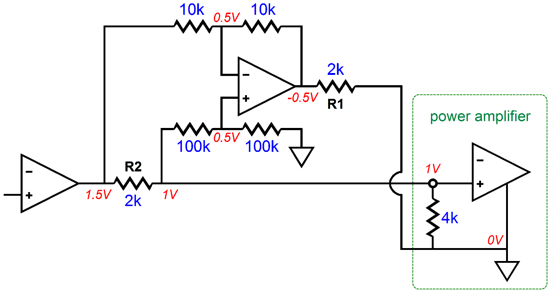
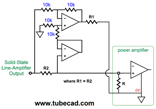
Resistor R2's value has been upped to 2k, half of the input resistance of the power amplifier. The differential amplifier measures the 0.5V voltage drop across R2 and puts out -0.5V, which ensures that the 0V voltage null occurs within the power amplifier. Note that an unbalanced signal source is used and that normal RCA-terminated interconnect is used. What is not normal is that this line-stage amplifier's ground is not directly connected to the power amplifier's ground. If a different power amplifier were used, say one with an input impedance of 47k, no part values need to change in the line-stage amplifier. If only I were a patent attorney. In the above schematic, there is a mathematical error, which I purposely left in place. Why? So as to avoid confusing anyone any more than absolutely necessary. The problem is that the 4k resistance is also shunted by the two 100k resistors, making for a 200k resistance in parallel with the 4k, which combines to create a resistance of 3,922 ohms. One workaround is the use of a partial instrumentation amplifier, as shown below.
The added OpAmp offers its very high input impedance, so that the power amplifier's input impedance is not shunted by any meaningful resistance. An instrumentation (or instrumental) amplifier holds three discrete circuits: one differential amplifier and two buffers.
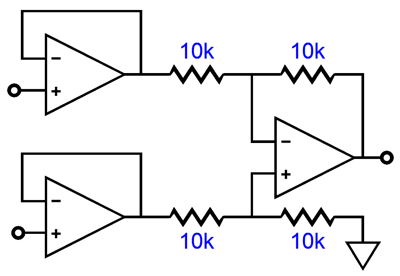
The two buffers present a near-infinite input impedance, which allows the differential functioning to work without dragging down what is being measured, which explains why instrumentation amplifiers are used in so many pieces of test equipment. Note that the schematic stated "Solid-State Line Amplifier Output." Why? The 10k resistor that feeds the differential amplifier's inverting input will drag down many tube line stages or result in limit low-frequency extension, due to small-valued coupling capacitors. The workaround is to go the full monty and use two buffers.
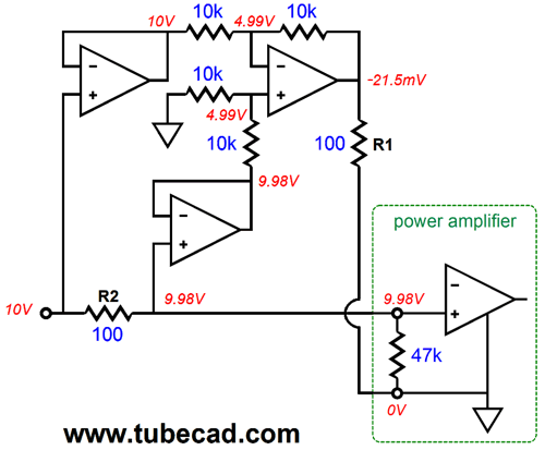
The following schematic use a crazy hot input voltage of 10V to make the voltage relationships more obvious.
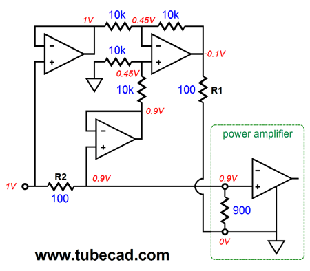
Well, even with 10V, the differential amplifier only puts outs -21.5mV. Okay, lets use a different power amplifier input resistance, one low enough to make a big result, say a brutal 900 ohms, which will still allow us to use a more reasonable 1V of input voltage.
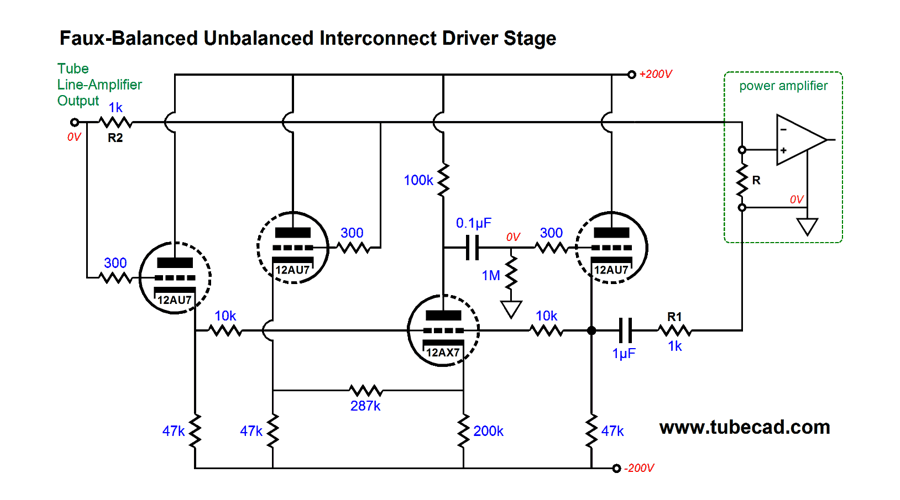
The 900-ohm resistance sees only 0.9V of the ordinal 1V, while the differential amplifier puts out -0.1V. The result is that 0V occurs within the power amplifier and a regular RCA-plug-terminated interconnect can be used. This set only makes sense if the amplifier is a stereo design with a single ground shared between channels or with two monobloc amplifiers whose signal grounds and chassis are directly tied to the house ground. That's all very nice, John, but where are the tubes? All in good time. When I first came up with this setup (and indeed after I began writing this post), my belief was that an all-tube version would be a nightmare to design, as a solid-state instrumentation amplifiers, such as the AD620ANZ, hold a fistful of transistors (possibly a hundred of them altogether) and resistors. The stunning wonder of triodes, however, is that you can do so much with so little. Many line-stage amplifiers consist of only one triode per channel. Amazing, when you stop to think about it. Well, after some serious doodling on the back of junk-mail envelopes, several cups of coffee, a little inspiration, and some testing in SPICE, the following circuit was born.
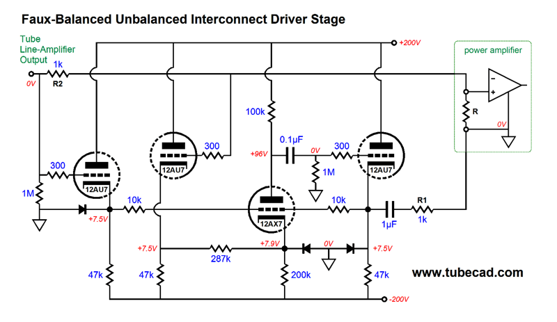
A bipolar power supply is needed, of course; and only two coupling capacitors are used. The tube complement would be a 12AU7 and 12DW7, which explains how the 12AX7 triode snuck into the circuit. The AC voltages on either side of resistor R2 are captured by the two 12AU7-based cathode followers. The 12DW7 triodes define a differential amplifier. Yes, with just two tubes and a resistors and capacitors we can create a fine instrumental amplifier. The wonder of tubes. Okay, as the above schematic stands, it is incomplete, as some safety features must be added.
The tree diodes, which can be 1N4007 types, save the triodes at start-up, when the cathodes are cold and not conducting. The added 1M resistor gives the circuit a path to ground in the absence of line-stage and power amplifiers.
Next Time
//JRB
User Guides for GlassWare Software
For those of you who still have old computers running Windows XP (32-bit) or any other Windows 32-bit OS, I have setup the download availability of my old old standards: Tube CAD, SE Amp CAD, and Audio Gadgets. The downloads are at the GlassWare-Yahoo store and the price is only $9.95 for each program. http://glass-ware.stores.yahoo.net/adsoffromgla.html So many have asked that I had to do it. WARNING: THESE THREE PROGRAMS WILL NOT RUN UNDER VISTA 64-Bit or WINDOWS 7 & 8 or any other 64-bit OS. I do plan on remaking all of these programs into 64-bit versions, but it will be a huge ordeal, as programming requires vast chunks of noise-free time, something very rare with children running about. Ideally, I would love to come out with versions that run on iPads and Android-OS tablets. //JRB |
Kit User Guide PDFs
E-mail from GlassWare Customers
High-quality, double-sided, extra thick, 2-oz traces, plated-through holes, dual sets of resistor pads and pads for two coupling capacitors. Stereo and mono, octal and 9-pin printed circuit boards available.  Aikido PCBs for as little as $24 http://glass-ware.stores.yahoo.net/ Support the Tube CAD Journal & get an extremely powerful push-pull tube-amplifier simulator for TCJ Push-Pull Calculator
TCJ PPC Version 2 Improvements Rebuilt simulation engine *User definable
Download or CD ROM For more information, please visit our Web site : To purchase, please visit our Yahoo Store: |
|||


| www.tubecad.com Copyright © 1999-2016 GlassWare All Rights Reserved |