| John Broskie's Guide to Tube Circuit Analysis & Design |
08 September 2021 Post Number 544
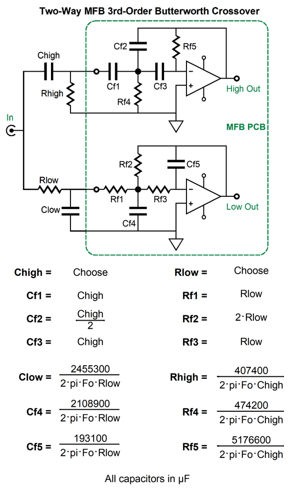
3rd-Order Butterworth MFB Crossover
Tube Phono and Line Amplifier
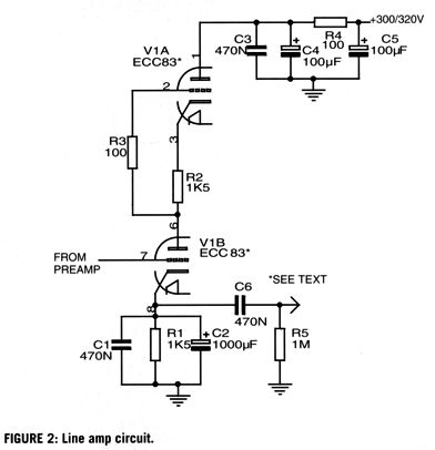
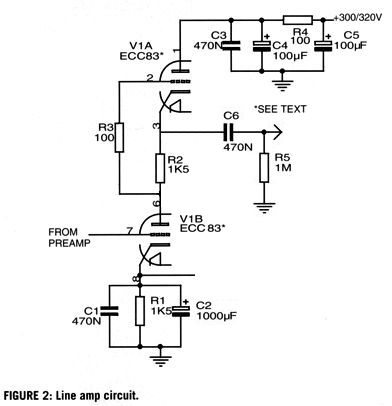
My guess is that an SRPP was intended, as no output signal would be forthcoming with the output taken at the cathode, a cathode that is shunted to ground through a 1kµF capacitor. Here is what it should have looked like.
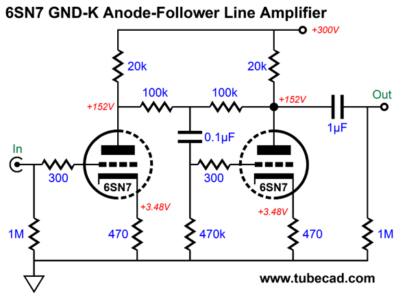
I think the 12AX7 is a truly bad choice for a line-stage amplifier, as it is so damn wimpy, drawing less 1mA in this circuit. In addition, who needs a gain of 1:54 (+34.6dB)? Not me. A much better choice is the 6CG7, 6SN7, 12AU7, 12BH7, 5687, or ECC99—all will deliver a much lower gain and output impedance. Moreover, the required higher idle-current flow will help cut through the interconnect capacitance. Remember, it takes current to quickly charge and discharge capacitance. In fact, one formula for slew-rate is SR = I/C. Put differently, the required current to achieve a specified slew-rate into a given capacitance is equal to the capacitance against the slew-rate. I would do something different, as you would expect. Here is a simple line-stage amplifier based on the 6SN7 that cascades a grounded-cathode amplifier into an anode follower.
The anode follower functions as an inverting cathode follower of sorts, as it delivers a low output impedance and low distortion—along with the possibility of selectable gain, both up and down. In this example, the anode follower's gain is less than one, coming in at 1:0.816 (-1.77dB). The entire amplifier's output impedance is about 1300 ohms and its gain is 1:8.3 (+18.4dB. The output signal is non-inverting. The THD in SPICE simulation was below 0.1% at 1Vpk at 1kHz into 100k. The only disappointing measurement is that its PSRR is only -11.4dB. (Mind you, a comparable SRPP would only deliver -6dB). The workaround, as so often is the case, is to inject some Aikido mojo, this time in the form of my cynosure resistor and capacitor.
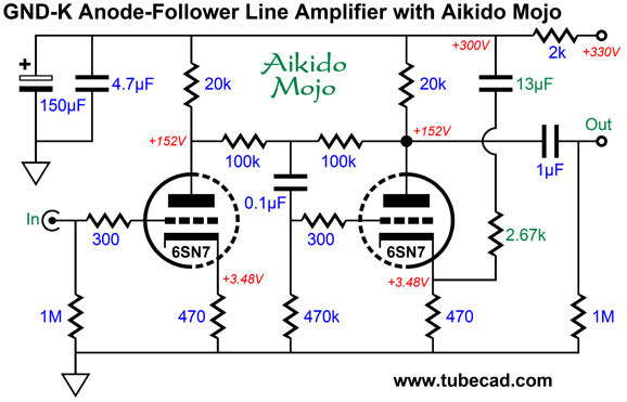
Now, the PSRR is a respectable -52dB. Adding an RC filter to the B+ voltage, say a 2k resistor and 150µF capacitor, brings the PSRR down to -100dB at 120Hz. The internal 0.1µF coupling capacitor dictates the 13µF cynosure capacitor value. In other words, don't change the values. In addition, don't shunt the cathode resistors with capacitors. This line-stage amplifier did not appear in isolation, as the designer, Jim Ryan, also provided a phono preamp. His four goals were two gain stages, no global negative feedback, a passive RIAA equalization network that uses no electrolytic capacitors, and a low output impedance. The last goal was required, as his volume potentiometer was 10k in resistance.
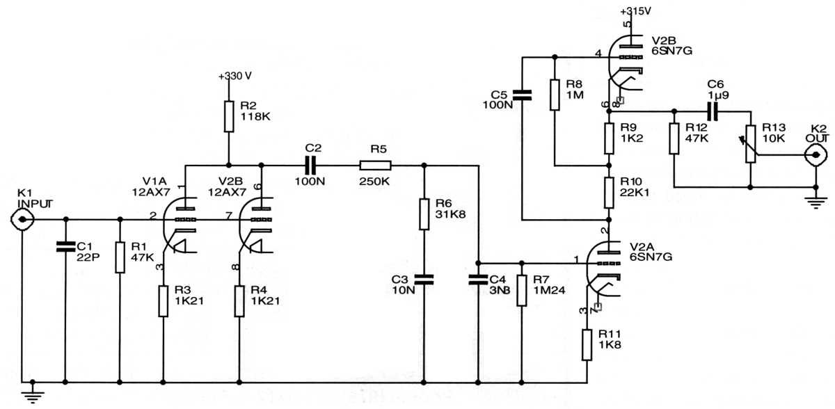
I see three problems with the phono stage. The 12AX7 input tube isn't all that quiet to begin with, which is why I have pretty much given up on this tube in phono stages. Second, the 12AX7's plate resistance forms a big chunk of the passive RIAA equalization network, which means that tube aging and different brand 12AX7s will alter the equalization. Third, the top 6SN7 triode's cathode sits 180Vdc above ground, which makes powering its heater element a problem, due to the huge voltage differential between 6SN7 triode cathodes. Even if we split the difference and reference the heater power supply to 90Vdc, each 6SN7 triode will see a 90V voltage differential between its cathode and heater. (As will the 12AX7 cathodes.) Here is how I would do it.
This is the quick overview of the circuit, with far fewer trees in the way of seeing the forest. We see an input gain stage followed by a cathode follower and then a passive RIAA equalization network, which then feeds the horizontal SRPP gain stage its signal. The MUR410G rectifier-bias is a tad unusual, but it is quite effective; in addition, we sidestep the problem of using bypass electrolytic capacitors, as a 47nF low-voltage film capacitor is sufficient. (A value larger than this causes high-frequency peaking, which might be desirable in a phono preamp.) The second stage consists of a horizontal SRPP, appearances to the contrary. By going horizontal, we narrowed the voltage differential between 6SN7 cathodes by about 50V. Thus, we can reference the heater power supply to +60Vdc. Now, let's see the full version.
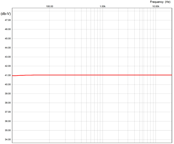
All the bells and whistles are in place. The three 12AX7 triodes in parallel help reduce the noise a bit, but the big noise reduction obtains from the absence of cathode resistors, as the cathode will amplify the resistor noise. Each 12AX7 gets its own rectifier and bypass capacitor (200nF), which prevents current-hogging, not that this is a big problem with this tube. The 12AU7-based cathode follower both offers a low output impedance and a balancing anti-phase current draw to the three parallel 12AX7 triodes. By the way, the 12AU7 triode is part of the 12DW7/ECC832/7247 tube. With the cathode follower's far lower output impedance, we can reduce the RIAA equalization network part values by tenfold, which will further reduce noise due to the lower resistor values. The phono preamps final gain is 41dB. In SPICE simulation, the frequency response was flat to within 0.1dB from 20Hz to 20kHz.
If you prefer to limit the number of tubes to four for the phono stage, then we could use a single 12DW7. Going in the opposite direction, we could add additional 12AX7 tubes to the first stage, say a total of five or seven 12AX7 triodes in parallel, which will further reduce noise. If I were actually going to build this preamp, I would replace the horizontal SRPP with either an Aikido gain stage or the same topology that was used in the line stage amplifier, i.e. the GKA and anode follower pairing, with added Aikido Mojo. While putting away the stray copy of audioXpress, another cover caught my eye, May 2001's cover. "Zero Net Phase Shift Filters" was the article title that grabbed my attention. Then I saw another title, "Try a Transient Perfect Passive Crossover." It was like finding gold in your backyard.
Kreskovsky Transient Perfect 2nd-Order Crossover
In the conventional 2nd-order crossover, each driver experiences a 90-degree phase shift at the crossover frequency, adding up to a 180-degree difference and a deep output null at the crossover frequency with in-phase drivers. The workaround is to flip one of the driver's phase, so zero-degrees of phase exists between the drivers. The Butterworth 2nd-order crossover alignment (i.e. the mathematical relationship between crossover part values) yields a -3dB attenuation for each driver at the crossover frequency. This is not good. Two drivers delivering the same signal, in phase, sum to a +6dB boost of SPL. Thus, the two -3dB outputs result in a +3dB boost at the crossover frequency. So why was the Butterworth 2nd-order crossover so damn popular for decades? Possibly, many thought that since the 1st-order and 3rd-order Butterworth crossovers were down -3dB at the crossover frequency, all crossovers must be down -3dB. The more likely reason, however, is that the Butterworth 2nd-order crossover alignment delivers a flat impedance equal to the driver impedance. In the era of tube-based power amplifiers this was vitally important, as a non-flat impedance would throw all the load-line calculations off.
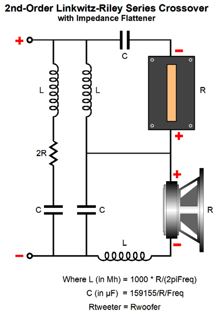
The workaround offered by Linkwitz and Riley was to use a different crossover alignment with a Q of 0.5, not the Butterworth's Q of 0.707, which results in each driver being down -6dB at the crossover frequency. The math is simple, -6dB + 6dB = 0dB. No bump at the crossover frequency. The problem now is that the loudspeaker impedance is no longer flat; instead, it rises to a peak twice the nominal driver impedance at the crossover frequency. This is not a big deal for most solid-state power amplifiers, but it does present a problem to tube-based, transformer-coupled power amplifiers that assume a fixed load impedance. In addition, current-output power amplifiers will produce a +6dB hump at the crossover frequency. My workaround is to add an impedance-flattening network.
With the my impedance-flattening network in place, tube-based and current-output amplifiers will be happy.
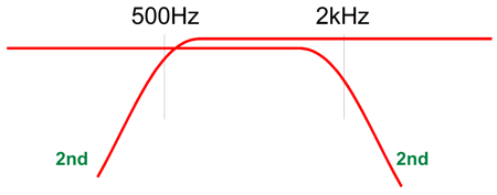
Returning to the Kreskovsky 2nd-order crossover, his solution is to overlap the crossover frequencies. For example, instead of just one crossover frequency at 1kHz, we would use two, say one at 500Hz for the high-frequency driver and 2kHz for the low-frequency driver. The two-octave overlap moves the driver phase shifts apart enough that the two drivers can be wired in phase, which will create a small dip—not a deep suck-out—in the frequency response centered at the nominal crossover frequency; in this example, 1kHz. The dip results from the drivers not being 90-degrees apart in phase, but 120 degrees.
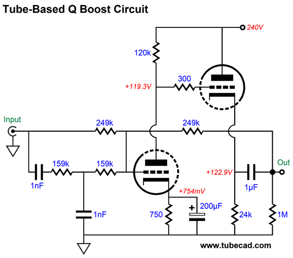
Kreskovsky then applies a boost filter centered at the nominal crossover frequency. The result is a flat frequency response and phase response. Really? Really—well, at least in SPICE simulations. Starting with the all-passive implementation, here is the circuit.
Only three extra parts (a capacitor, inductor, and resistor) were added to what otherwise looks like a conventional 2nd-order two-way crossover. These three parts form a frequency-bulge (bump, lump, protuberance) that undoes the dip in frequency response. Kreskovsky points out that the low-pass and high-pass filter alignment Q cannot exceed 0.5, as the 2nd-order RCL network won't be able to produce a flat loudspeaker output. He further stipulates that the two-crossover-frequencies overlap ratio not exceed a factor of 4 and that the compensating boost should not exceed 6dB. In his design example, the boost is 4dB and he uses an overlap parameter of 3.25 and the two 2nd-order filters present a Q of 0.425, while the RCL network Q is 0.18. Thus, given a nominal crossover frequency of 1kHz, the low-pass filter frequency is equal to 1000/Sqrt(3.25) or 1000/1.8 or 555Hz, while the high-pass filter frequency is equal to 1000*Sqrt(3.25) or 1000*1.8 or 1800Hz. The 2nd-order crossover capacitors equal 159155Qf/(FR), where F is the filter frequency, not the nominal crossover frequency (Fc), and Qf is the filter Q and R is the driver resistance. The inductor value is found from 159.155R/(Qf*F). Capacitors are in µF and inductors are in mH. The equalization RCL network resistor is found by dividing the boost in dBs by 20 and we ten to the quotient power, which turns dBs into simple numerical gain; in this example, 1.585. Next, we multiply 1.585 against the driver resistance and then subtract the driver resistance from the product: Rn = 10^(db/20) x Rdriver. The capacitor equal 159155/(QnetFcR), where Fc is the nominal crossover frequency, and Qnet is the RCL network Q and R is the RCL resistor. The inductor value is found from 159.155RdriverQnet/Fc. Capacitor is in µF and inductor is in mH.
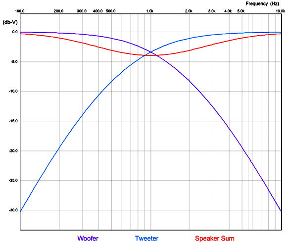
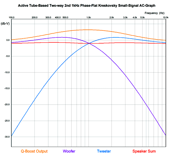
My expectations were low as I ran the first simulation, as I doubted the altered 2nd-order crossover would provide a flat enough load impedance for the frequency-boost network to work well. I was wrong.
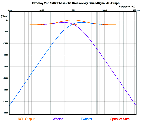
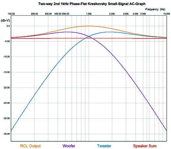
As we can see the speaker sum is flat. Here is the result, but zoomed in.
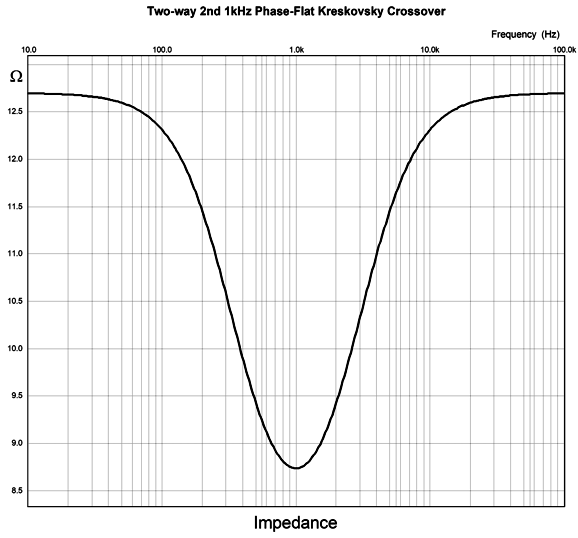
The crossover frequency-boost network frequency is 1kHz, but the two filters are tuned to other frequencies, 555Hz for the high-frequency driver and 1803Hz for the low-frequency driver. Because the frequency-boost network is passive, it exacts a 4dB insertion loss. In other words, to make a 4dB peak at 1kHz requires reducing frequencies above and below 1kHz by 4dB. Won't this passive network undo the power amplifier's damping factor? It will. Won't it also get hot? Its resistor will. I remember David Manly, the founder of VTL and Manley and ViTaL records, explaining to me how damping factor was the most overrated audio specification. He laughed that notion that an audiophile would choose the power amplifier with a damping factor of 400 over the one that offered only 200. He pointed out that the woofer's own voicecoil resistance completely undermined the importance of an amplifier's 0.001-ohm output impedance. I also remember an accomplished EE friend explaining that, based on his experiments, 2 ohms was the optimal output impedance. Many single-ended tube-based power amplifier present output impedances greater than 4 ohms. Okay, having said all that, the boost network's 4.7-ohm resistor will increase the loudspeaker's Qes and Qtc. By how much? It depends on the woofer's Thiele-Small parameters. But we can expect an increase. This is only a problem if we fail to incorporate the 4.7-ohm resistance in our loudspeaker design. For example, we might purposely use an extremely over-damped woofer, knowing that the added series resistance will loosen it up to a desired Qtc. Qes (new) = Qes*(R + Re) / Re Where Qes is the electrical part of woofers Q-Factor , Re the woofer's DC resistance, and R the added RCL resistance.As for the 4.7-ohm resistor getting hot, much depends on the crossover frequency, as most music-based energy is located below 600Hz or so. Thus, a crossover frequency of 2k would lessen its heat dissipation greatly, whereas 300Hz would increase it greatly. The loudspeaker's impedance with the Kreskovsky 2nd-order passive crossover is not flat.
Bear in mind that this is a speaker with two 8-ohm drivers. (While I was in college in the late 1970s, I designed my own phase-flat crossover and it, too, entailed an insertion loss of about 4dB. I loved the sound, but hated the need for a more powerful amplifier to override the efficiency loss. Throwing away solid-state class-D amplifier watts is no big deal, but it is extremely painful with tube-based power amplifiers.) What if we place the needed frequency-bump network in front of the power amplifier instead, with the rest of the passive crossover in the speaker enclosure? A much better idea. If nothing else, we won't be throwing away potential watts and no extra heat. The first circuit Kreskovsky shows in a later issue of audioXpress, December 2002, uses an OpAmp and inductor and capacitor to create the needed amount of boost and the desired countervailing Q.
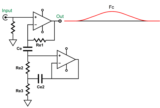
Super simple, but the inductor is a huge liability with audio-frequencies, but not so with radio frequencies. Why? Huge values of inductance needed means huge lengths of inductor wire needed, which in turn means high DCR. For example, in his 2002 article, Kreskovsky shows a 234.5mH inductor being used. In addition, inductors are natural hum magnets. Kreskovsky's workaround is to replace the inductor with a gyrator circuit that will require an additional OpAmp.
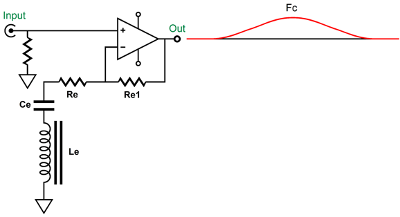
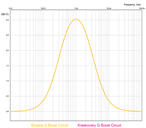
A gyrator can simulate an inductor by transforming a load capacitance into an effectively inductive load impedance. We can use an OpAmp or a single transistor or triode to create a gyrator circuit. This bothered me, as I instantly try to translate solid-state circuits in tube-based circuits. Adding an additional tube circuit to simulate a large inductor looks like an added pain. In other words, I sought an alternative. Here is one possibility. The boost is only 3dB. Here is the comparison between this boost circuit and the gyrator version.
There is a difference, but it is small. The gyrator version, with 20k resistors instead of 19.9k resistors, creates a boost 3.025dB big, while the single OpAmp version delivers 3.045dB, a 0.02dB difference. If we replace the single 20k resistors with a pair of 28.7k and 64.9k resistors in parallel (19.9k), the difference falls to 0.003dB, which is shown above. Considering that we will ultimately be dealing with loudspeaker drivers, whose frequency response are as flat as the Alps, where +/-3dB is considered really flat—there is no real difference. Now the interesting part: we translate the solid-state circuit into a tube-based circuit.
A total of six triodes and three twin-triode tubes. The input circuit that creates the needed frequency bump uses a 12DW7/ECC832/7247 dissimilar-triodes tube, with the 12AX7 triode in the input position to increase its open-loop gain. The two MFB 2nd-order filters use 6DJ8 tubes and exhibit a Linkwitz-Riley alignment (i.e. Q of 0.5). The high-pass filter (on top) is tuned to 555Hz, while the low-pass filter (below) is tuned to 1800Hz; thus the overlap ratio is 3.24, whose square-root is 1.8. Not as clean as the solid-state version with idealized OpAmps. Why not? Coupling capacitors and lower open-loop gain. The next test is the important one" square wave summing.
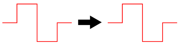
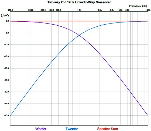
It may not look all that square, but compared to a two-way 2nd-order Linkwitz-Riley 1kHz crossover, it's dang square.
Conventional 2nd-order crossovers, be they Butterworth or Linkwitz-Riley alignments, exhibit a shifting phase from 0 to -180 degrees, with the 90-degrees of phase shift at the crossover frequency. This makes passing a square-wave impossible. Summery: is John Kreskovsky's phase-flat crossover a good idea? Well, it is certainly interesting, but it is not all that practical. Let's zoom out and ask why a crossover is needed at all? If speaker drivers were perfect, we wouldn't need crossovers, as a perfect driver could reproduce all frequencies and at all levels of SPL. Real drivers are far from perfect; thus, the need for crossovers. Kreskovsky's phase-flat crossover is more of a speaker over-lapper than a crossover. Sadly, this is the last thing a delicate tweeter wants, as the whole point of the crossover was to limit its low-frequency extension, not increase it. Likewise, the woofer is too sluggish and too big to produce high frequencies, which a big overlap would require. The possible exception might be fullrange drivers. Here the overlap of octaves is not the big problem it is with woofers and tweeters. Another possibility is headphones, which could hold two identical drivers and house the crossover externally. A two-way, phase-flat headphone with a low nominal crossover frequency of 600Hz might prove stellar.
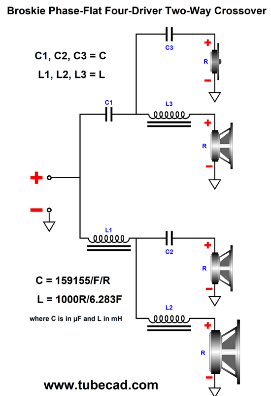
Broskie Phase-Flat 2nd-Order Crossover
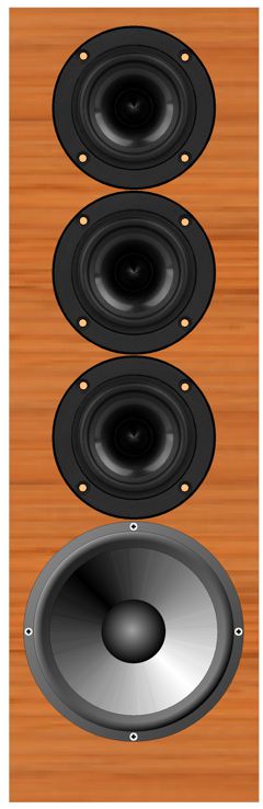
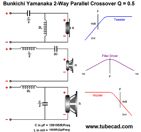
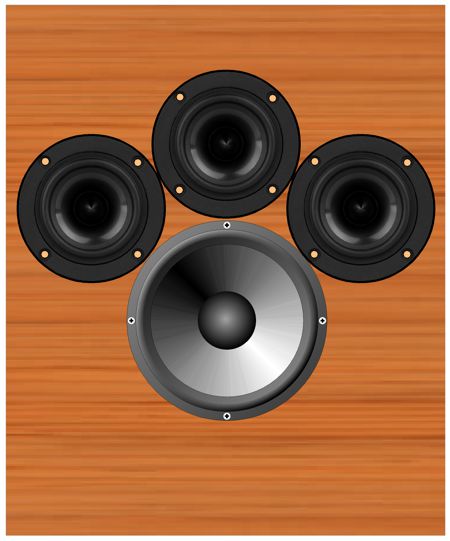
The three identical smaller drivers are fullranges, while the single larger driver is a proper woofer. In spite of there being four drivers, this is a fundamentally a two-way system, with a single crossover frequency, say 640Hz. Why 640Hz? Several reasons come to mind. The first is that 640Hz nicely divides the music spectrum, which for acoustic instruments spans from about 35 Hz to 12kHz. If we multiply 35 by 12000, we get 420k. If we then find the square root of 420k, we will have the geometric center frequency, 648Hz. Second, the wavelength of 640Hz is 21 inches, which is large enough to prevent severe lobbing effects with the three fullranges, as maximum distance between cone centers is 8 inches; even the woofer's center to the topmost fullrange center is only 12 inches. Third, with 8-ohm drivers the needed inductor value for a 640Hz crossover frequency is 2mH, a readily available value. The capacitor value is 31µF, which can easily be made up from a 30µF polypropylene film capacitor in parallel with a high-grade 1µF capacitor. Returning to the picture, I didn't have it in mind when I created the following phase-flat crossover in 2009, so I prematurely discarded the crossover. In other words, I was envisioning a crossover frequency closer to 4kHz and 1-inch dome tweeters. In addition, I saw it as simply a reinvention of the Bunkichi Yamanaka phase-flat crossover (1967) that was later used in the Technics SB-7000 three-driver two-way loudspeaker and, later, in a B & O speaker.
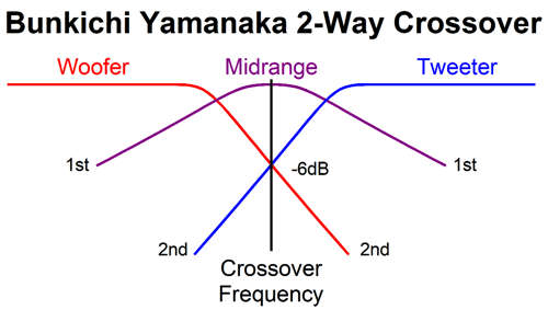
The Yamanaka crossover uses a 2nd-order crossover with a Q of 0.5, the same as (and pre-dating) the Linkwitz-Riley, but with both drivers in phase with each other, which creates a big suck-out at the crossover frequency that must be filled in with a "filler" driver. This is a three-driver two-way system. The big problem is that the filler driver must present an SPL 6dB louder than the woofer and tweeter. In addition, the filler driver does not see 2nd-order slopes, but 1st-order slopes, which are shallow and offer little protection from the powerful bass frequencies.
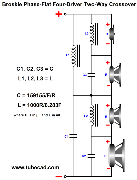
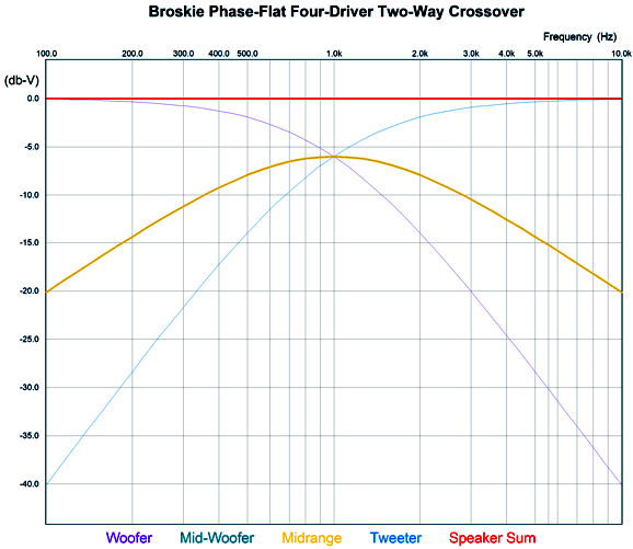
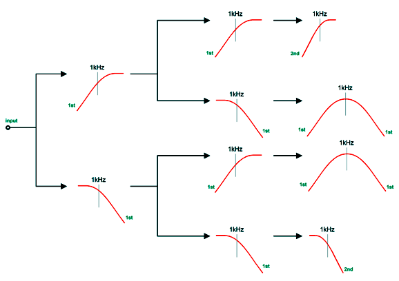
My crossover uses four drivers in a two-way system. It, too, delivers a flat phase and can pass a square wave. Unlike the Yamanaka crossover, the two filler drivers need only present the same SPL as the woofer and tweeter. Moreover, the filler drivers output will be -6dB relative to the woofer and tweeter. This is a huge advantage, as -6dB means 50% as much voltage, which in turn means 25% of the power. Here is my 2009 schematic. The crossover is arranged in the series configuration, which usually works best with voltage-out power amplifiers. But as this crossover presents a flat impedance, it works equally well with current-out and high-output-impedance power amplifiers. All the capacitor and inductor values are the same, which makes bulk purchases possible. The two filler drivers (Mid-Woofer and Midrange in the graph) cover the same bandwidth and share the same center frequency. In fact, they overlap so tightly that it is hard to see in the graph shown above that there are four plotlines, not three. We can use the parallel version instead, using the same capacitor and inductor values. Perhaps it is more obvious with this arrangement that we are cascading 1st-order crossovers to create the 2nd-order crossover and the two filler drivers outputs. Here is the flowchart version. As we can see, bi-wiring is possible in this arrangement. I prefer the series arrangement as it is more part-value intolerant. See post 481 for more details. Another arrangement would be to place the filler drivers at the sides.
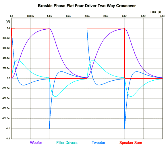
As long as the crossover frequency is low enough, we can pretty much place the drivers where we want. As the crossover frequency increases, however, the layout becomes far more critical, as the wavelengths decrease. Okay, now for the big test: square waves (actually repeated positive square pulses).
Looks square to me. Note how the tweeter must exhibit an insanely fast rise time, which implies an insanely high-frequency bandwidth. Fortunately we listen to music, not test signals. Nonetheless, the square-wave test is excellent for revealing both phase and frequency aberrations.
Music Recommendation: Unfamiliar Female Singers I enjoy firing up the Amazon Music app and searching for a well-known song, such as California Dremin' and seeing hundreds of covers of the famous song. Recently, I did this with The Beatle's hit, Good Day Sunshine.
I quickly give each cover a brief listen, and those I like I add to a new playlist. Once I have about ten covers collected, I play the list. I find that this procedure is the best way to discover musicians and singers I will like but do not know presently. Why? Stop and think about it: when we hear a new singer singing a new song in new genre or style, we have three potential things to not like; In contrast, with songs we know in a genere we know, we can evaluate only one thing: the singer. One singer that impressed me greatly is probably known to everyone under 30, Haley Reinhart. Give the YouTube video a play. She has at least three things going for her: she is attractive, she can sing, and she has competed on the American Idol talent show, coming in third in 2011. Wikipedia informs me that she has since won much critical acclaim and awards, including a platinum album. I am glad that I knew nothing about her, as I was able to listen to her voice cleanly, with out prejudice. She can sing. She handles many styles, such as blues, soul, jazz, retro, hard-chick rock, with ease and grace and an occasional growl.
Next, w hen searching for covers of the famous Ten Years After song, I'd Love To Change The World, I discovered Piper Hays. Interestingly enough, I had brought my playlist to a friend's house and we went through the covers of the song. When we hit Ms. Hays' cover, my friend blurted out, "Whoa, that's it!" He was right. Hers was the standout cover. By the way, she altered the lyrics. Where Alvin Lee had written, Tax the rich, feed the poor, 'til there are no rich no more... she sang, Tax the rich, feed the poor, 'til the poor don't starve no more... which undoes some of the latent cynicism of the original. She is young, however, with plenty of time to ripen into a mature scorn for the self-professed motives, virtue, or integrity of others. In the mean time, we can enjoy her youthful optimism and blusey singing.
//JRB
This post took a ton of effort and time to put together. If you just discovered my website, welcome aboard. If you are a long-time reader, then help me make more posts like it. Benjamin Franklin famously said that "time is money"—and he was painfully right, as was the first person to say it, Antiphon, a fifth-century Athenian orator. And Logan Pearsall Smith not so famously said, "My life is a bubble; but how much solid cash it costs to keep afloat that Bubble!" Keeping the bubble known as the Tube CAD Journal afloat takes a huge amount of time, so help keep it afloat. Please think about supporting me at Patreon.
User Guides for GlassWare Software
For those of you who still have old computers running Windows XP (32-bit) or any other Windows 32-bit OS, I have setup the download availability of my old old standards: Tube CAD, SE Amp CAD, and Audio Gadgets. The downloads are at the GlassWare-Yahoo store and the price is only $9.95 for each program. http://glass-ware.stores.yahoo.net/adsoffromgla.html So many have asked that I had to do it. WARNING: THESE THREE PROGRAMS WILL NOT RUN UNDER VISTA 64-Bit or WINDOWS 7, 8, and 10 if the OS is not 32-bit or if the OS is 64-bit. I do plan on remaking all of these programs into 64-bit versions, but it will be a huge ordeal, as programming requires vast chunks of noise-free time, something very rare with children running about. Ideally, I would love to come out with versions that run on iPads and Android-OS tablets.
|
I know that some readers wish to avoid Patreon, so here is a PayPal donate button instead. Thanks. John Broskie
John Gives
Special Thanks to the Special 86
I am truly stunned and appreciative of their support. In addition I want to thank the following patrons:
All of your support makes a big difference. I would love to arrive at the point where creating my posts was my top priority of the day, not something that I have to steal time from other obligations to do. The more support I get, the higher up these posts move up in deserving attention.
If you have been reading my posts, you know that my lifetime goal is reaching post number one thousand. I have 456 more to go. My second goal is to gather 100 patrons. I have 14 patrons to go. Help me get there.
Only $9.95
The Tube CAD Journal's first companion program, TCJ Filter Design lets you design a filter or crossover (passive, OpAmp or tube) without having to check out thick textbooks from the library and without having to breakout the scientific calculator. This program's goal is to provide a quick and easy display not only of the frequency response, but also of the resistor and capacitor values for a passive and active filters and crossovers. TCJ Filter Design is easy to use, but not lightweight, holding over 60 different filter topologies and up to four filter alignments: While the program's main concern is active filters, solid-state and tube, it also does passive filters. In fact, it can be used to calculate passive crossovers for use with speakers by entering 8 ohms as the terminating resistance. Click on the image below to see the full screen capture.
Tube crossovers are a major part of this program; both buffered and un-buffered tube based filters along with mono-polar and bipolar power supply topologies are covered. Available on a CD-ROM and a downloadable version (4 Megabytes). Download or CD ROM
|
|||


 The next step is to add the two active 2nd-order filters. Since we have been recently reviewing the MFB filter topology, here it is again based on a CCDA amplifier.
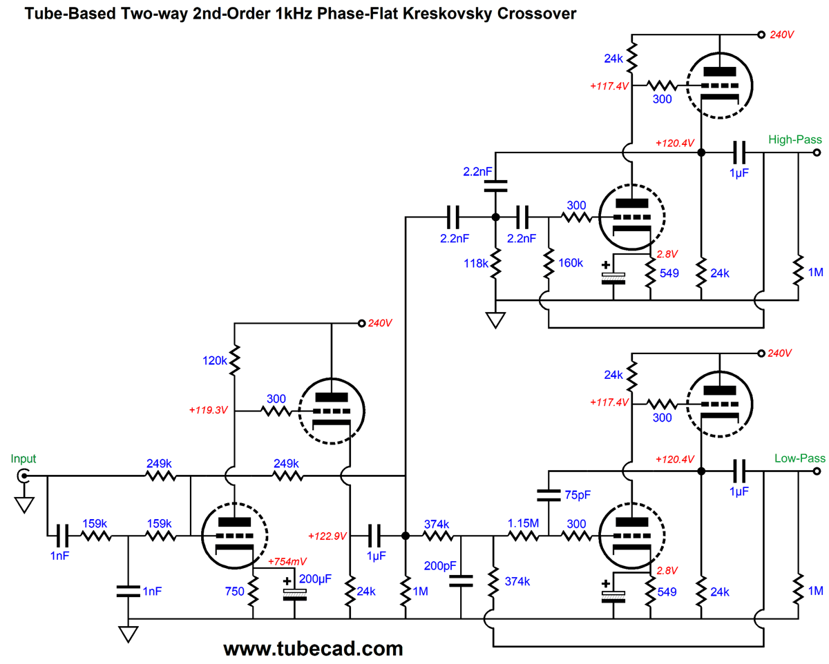


| www.tubecad.com Copyright © 1999-2021 GlassWare All Rights Reserved |