| John Broskie's Guide to Tube Circuit Analysis & Design |
|
02 December 2019 Post 485
Electrostatic Headphone Amplifier
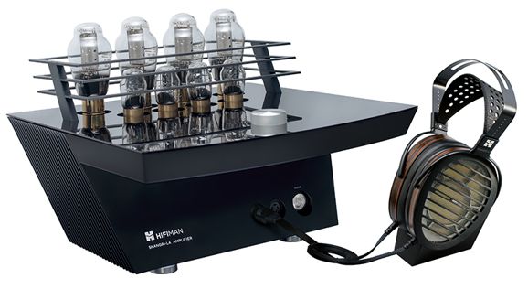
I have, however, listened to other electrostatic headphones at each RMAF, including the $50,000 pair with amplifier, the Shangri-La amplifier (that holds four 6SN7 and four 300B tubes) made by HiFiMAN. Still, I wanted to do an actual shootout between Sennheiser and Stax.
Well, I have been sitting on PCBs for an electrostatic headphone amplifier for nine years now. In addition, I knew that since I had just built my last headphone amplifier that I could build a new one in half the time, as I knew what to do and what not to do. Surprisingly enough, I was right. Half of the knowledge is mental and the other half hand memory. It didn't hurt that many of the tools and rill sizes I needed had not yet put away. (If I were to build a third headphone amplifier, it would take about a third of the time the first took, which is about as short a spell as I can ever manage, without resorting to assembly-line techniques.)
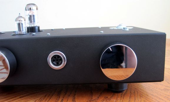
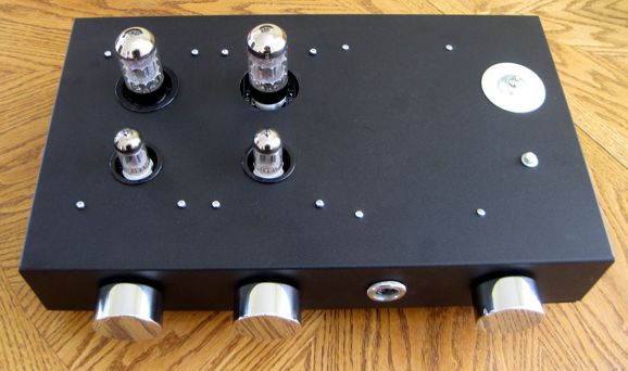
I mounted all the parts other than the tube sockets on the bottom of the PCB, so the tubes could poke through the chassis. The circuit is the same one I used over 30 years ago and which I described here several times, the first occurrence being in 1999. www.tubecad.com/november99/page8.html
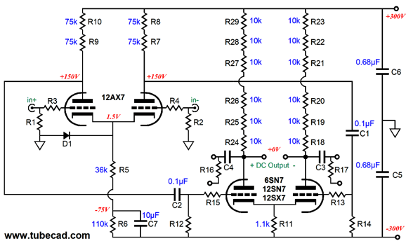
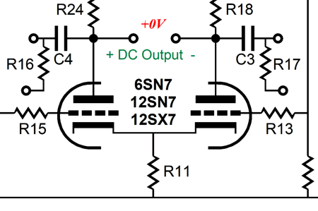
A 12AX7-based differential input stage cascades into a 6SN7-based differential output stage, with a +/-300Vdc bipolar power supply. Diode D1 protects the input tube at start-up, where its cathodes would otherwise see a 300-volt differential to its grids. Not good. Once the input tube heats up, the diode falls out of the circuit. The balanced output sits near ground potential and is DC coupled to the electrostatic headphone's stators. The circuit accepts either a balanced or an unbalanced input signal. In addition, the 10µF capacitor provokes some Aikido mojo that enhances the PSRR. Is that important with a balanced output? In theory, no; in practice, yes. In the mid-1980s, I performed the easy experiment of tack soldering one end of the 10µF capacitor in place, so I could quickly compare the sound with and without the PSRR enhancement. Definitely better with enhancement than without. Why? My guess is that although the power-supply noise cancels at the headphones, it still dirties the sound by inducing intermodulation distortion with the actual audio signal.
The way the Aikido mojo works is that the 6SN7 sees same amount of negative power-supply-rail noise at is grid as at its cathode; then the plate resistors and the triode with its un-bypassed cathode resistor define a two-resistor voltage divider of 50%. As the midpoint between -1 and +1 is 0, the plates sit at a power-supply noise null.
Speaking of plate resistors, the reason we find so many plate resistors in series is not only to ensure adequate power dissipation, but also to lessen voltage-induced distortion from the resistors. In my build, each 6SN7 triode sees six 10k/1W carbon-film resistors in series, which might seem excessively over rated, as each resistor only dissipates 0.25W. On the other hand, if a 6SN7 shorted (or the wrong tube were inserted), each resistor would dissipate 1W, as each resistor would experience a 100V voltage drop. In other words, the 1W rating was picked for the worst-case, not the typical dissipation.
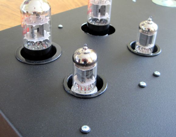
(The right channel's 6SN7 hole is missing is hole grommet. They were supposedly to arrive last Friday, but with the huge snow storm that blew through Colorado recently, delays are to be expected.) The 12AX7 is a high-mu triode and the 6SN7 is a medium-mu triode, which means we get a huge signal gain, about 570 at each stator. High gain is a good feature when an unbalanced input signal is used, but it does mean we must use either a 12AX7 or 5751 input tube, neither of which is supremely quiet. (I have stopped using the 12AX7 in my PH-2 phono stage, preferring to use 12AT7s throughout.) Perhaps because I am using the new Russian Mullard 12AX7, no hiss is heard. The input tube that I would like to try is the 12AY7 (6072), which were made with low-noise in mind.
The 6SN7 I used was a new JJ tube. In previous shootouts, the Russian reissue of the Tungsol 6SN7 came out on top. To be honest, the JJ 6SN7 sounds so good that I have yet to try the new Tung Sols or any American NOS 6SN7, which includes the 5692 that I used in my original electrostatic headphone amplifier.
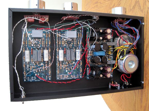
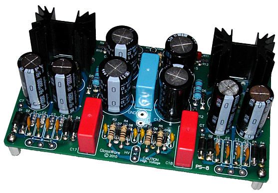
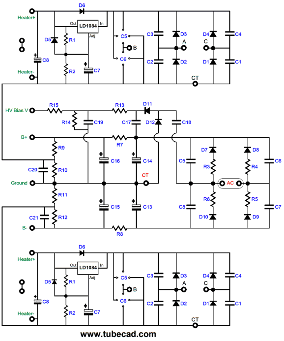
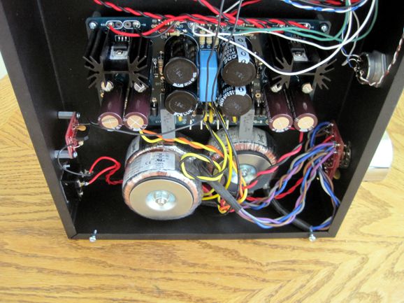
The PS-8 power supply was designed to work with the ES HPA-1 PCBs. It holds two separate low-voltage regulator heater power supplies and a high-voltage bipolar power supply that isn't regulated, but does hold two RC filters. Most importantly, the PS-8 power supply contains a voltage-doubler circuit that creates the 580Vdc bias voltage for the Stax headphones.
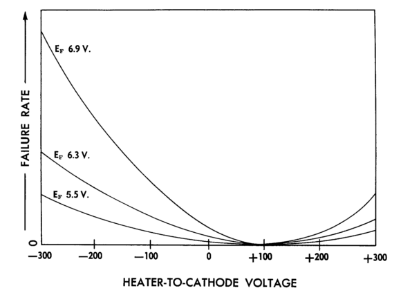
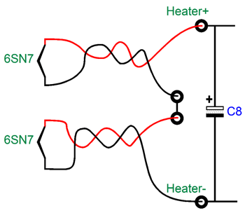
Note how the noval input tubes get their own heater regulator, as do the octal output tubes. Moreover, the heater regulators are voltage referenced to a slightly higher DC voltage than the heaters they heat. In other words, the 12AX7's heater elements see 12Vdc, which is referenced to 30Vdc, so the heaters are referenced to a positive voltage greater than the cathodes, which inhibits cathode interaction with the heater element and extends tube life.
Remember that actual current flows from negative to positive; thus, if the heater element is more positive than the cathode it heats, no current can flow from heater element to the cathode.
Three toroid power transformers are used: two 240Vac and one dual 12VAC secondaries. The two 240Vac transformer secondaries are wired in series to create 480Vac center-tapped.
If I lived where 230Vac to 240Vac wall voltages were used, I would wire the transformers thus:
If you live with 230Vac or 240Vac wall voltage, you might wonder why I didn't make the following arrangement.
The potential problem is that the center-tap may not actually fall exactly at the AC center. In contrast, when we use the two previous arrangement, we are certain to get a perfect center-tap.
One toroid sits physically atop the other. Both are wired in phase, but the top transformer has been physically flipped so the two AC fields about the transformers will cancel, as the two fields are in anti-phase in this arrangement. In the past, I tried running backwards a 60Vac toroid with two 120Vac primaries, wherein the 120Vac wall voltage entered the 60Vac winding and the two 120Vac windings became a 480Vac center-tap secondary. It mechanically hummed like crazy, alas. The two stacked toroids are quiet. Perhaps, mechanical vibration also cancels, much like the AC fields or like the two anti-phase air pumps in the more expensive quiet aquarium air pumps. One danger we might encounter with stacked toroid transformers, because the structure is so tall, is creating a shorted turn. Not good.
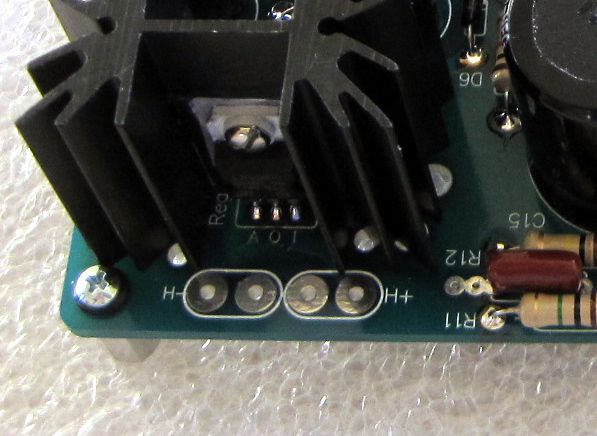
At no times can the metal enclosure and the toroid mounting screw touch at more than one place. If the top and bottom of the chassis touch the screw, it and the enclosure constitute a shorted turn of wire, which will blow a fuse and possibly damage the transformer. The Hammond chassis I used is 3 inches tall. Here is the problem: no one makes a 2.75 inch bolt; they do make 2.5- and 3-inch bolts. But 2.5-inch is too short; 3-inch, too long. I had a 3-inch bolt, but I could not find my hacksaw (must be out on loan), so I used the extra mounting washer to pull the 3-inch bolt up from the bottom panel. The two heater regulators are powered by a 25VA toroid with two 12Vac secondaries. I set the output voltages to 12Vdc. The two 6SN7 heaters are in series with each other.
The two heater pads in the center are wired together and floating. When using 6SN7 output tubes, instead of 12SN7, you solder a twisted pairs of wires for each 6SN7.
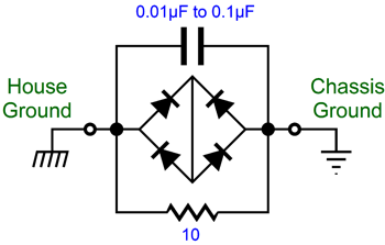
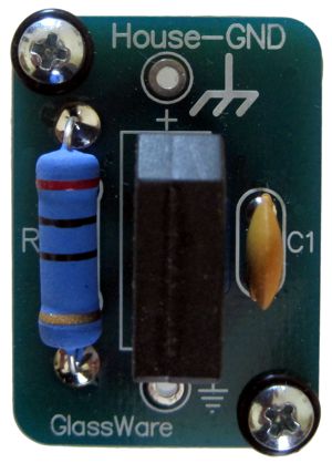
I added a House-Ground PCB and circuit.
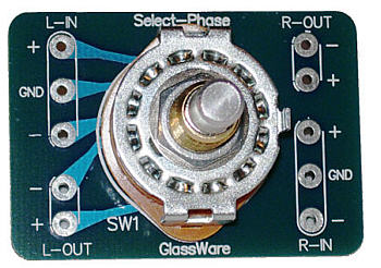
The power switch is one of my AC-Select types, which allow staggered turn on of the transformers, with the heater transformer turning on first. A three-position phase switch not only allows flipping the phase of the signal applied to the headphones, it also offers a mute in the center position.
Before turning on the headphone amplifier, I park the headphones at mute, which grounds all four stators, which further protects the 6SN7 output tubes, as at turn-on they only see a 300V voltage potential from cathode to plate, rather than 600V.
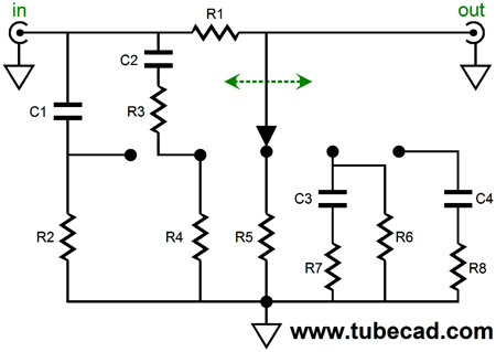
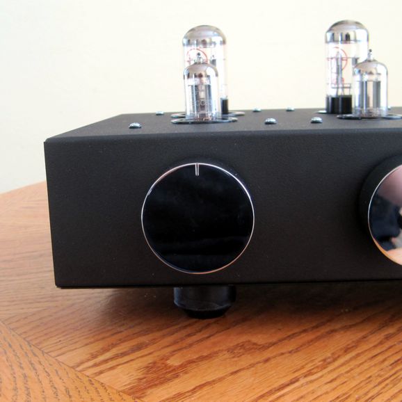
The last knob attaches to the original five-position Tilt Control, which is the first on the left side. I find this sonic control a godsend, as some female singers and certain recordings are just to piercing with the electrostatic headphones. (In the old days, I used a ten-foot extension cable for the headphones as a high-frequency filter, as its added capacitance dragged down the output stage enough to truncate the high-frequency bandwidth. The Tilt Control is far better, as I can rotate my way to listenable sound.) Recently, I discovered that I still owned a bag of Cardas RCA jacks that were designed by David Manley and hold a rhodium plating over silver plated brass. I used them on my previous headphone amplifier as well.
Okay, how does the electrostatic headphone amplifier sound? Dang fine. Shockingly good with no shocks. Actually, every once in a while I hear a single instrument—a saxophone, a plucked bass, a tambourine—during a recording that sounds so coherent and tight that I am startled, almost as if the instrument were being played in the room near me. Very spooky. With electrostatic headphones, you simply hear things that you never hear with any loudspeaker and with few other headphones; for example, classical musicians turning their sheet music over, floorboards creaking under the bass player and his fingerprints rubbing against the strings. In addition, you hear flubbed notes and clumsy recording-room edits that you never heard before. In other words, bad recordings sound bad, whereas many other headphones homogenize all recordings, smoothing over such defects, but at the cost of smearing clean recordings.
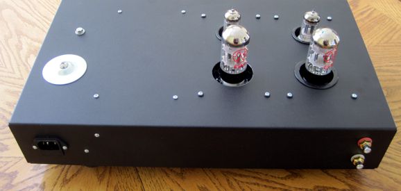
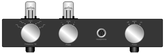
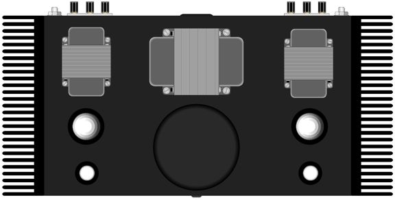
If you have never given electrostatic headphones an extended listen, you owe to yourself to do so—but please use a tube-based headphone amplifier, as most solid-state amplifier sound crazy cold and brittle in comparison. Speaking of comparisons, before I actually made my ES headphone amplifier, I drew it.
The scale on the tubes is wrong, but the rest is to scale. One thought I have had is that if I can find a plate-glass fabricator who can drill and seam sheet glass, I could make a snazzy front panel. In my town, there is a business that silkscreen reverse text and images on plexiglas for signs. Perhaps, they could do the same to dark plate glass. By the way, placing dark-tinted sheet glass atop black felt creates an amazing sight, as the black seems both luxurious and limitless.
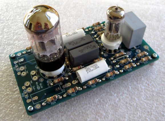
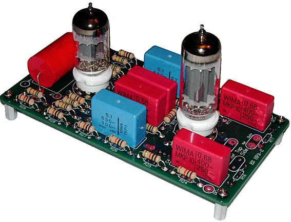
ES HPA-1 and ES HPA-2 and PS-8
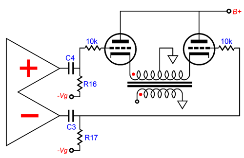
(This is a nine-year old photo, and I no longer use or sell those red Wima capacitors.) The best output tube for the ES HPA-2 is probably the 6CG7 or 12BH7 or ECC99. The ECC99's 400V plate voltage maximum rating and 3.5W dissipation rating commend the tube. Depending on how much gain you need, the input tube can be any tube from a 12AU7 to 12AX7. Dual-triode tubes, such as the 6AQ8 and 6N1P, can also be used. Wouldn't we always want the most gain possible, so only the 12AX7 would ever be used? No, as we might use either the ES HPA-1 or ES HPA-2 PCBs not to drive electrostatic headphones, but to drive inefficient push-pull output tubes, such as 6AS7s in a circlotron output stage or 845 output tubes in huge push-pull power amplifier. This explains why I made mono PCBs rather than a single stereo PCB. It also explains why I added pads on the PCBs for optional output coupling capacitors.
The two optional coupling capacitors (C3 & C4) get their own grid resistor (R16 & R17) that can independently attach to a negative power-supply bias voltage, so current balance between two output tubes can be set individually. By the way, these PCBs would make an excellent frontend for a push-pull cathode-follower output stage.
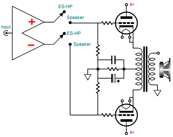
Cathode follower output stages are rare, in spite of the obvious benefits of low distortion and output impedance. Half of the reason they are rare is that huge balanced input signals are required. The other half is found in the need to use separate and floating heater power supplies, as each cathode will swing hundreds of volts, so its heater power supply (or AC secondary winding) must be referenced to the cathode. In post 382, I wrote about making a dual-use power amplifier, which could drive either loudspeaker or electrostatic headphones (but not both at once).
The cathode-follower output stage isn't powered while we listen to electrostatic headphones. When we listen to loudspeaker, the electrostatic headphone jack isn't connected to the ES HPA-1 outputs. Actually, switching would prove a tad more complicated, as we want the headphones to attach to the DC outputs, not the capacitor outputs. Still, we could use a two-deck three-position switch and knob to choose between the two outputs (and a mute center position). Mute is critical, when the phone rings or you are asked a question from another room. The ES HPA-1 and ES HPA-2 and PS-8 Kits are available now at the GlassWare/Yahoo store. Supplies are limited.
So why bother with a push-pull version, albeit a class-A push-pull version, when driving headphones? The single-ended ended version suffered from a small DC offset that the DC servo helped to reduce, but could not eliminate altogether. As I looked at the circuit, I saw that adding an additional coupling capacitor at the input would eliminate the DC offset.
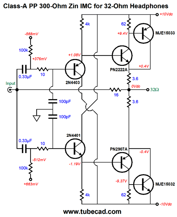
The more I thought about it, the push-pull version just screamed out to me, as I could see how a second DC servo could auto-bias the IMC for class-A operation.
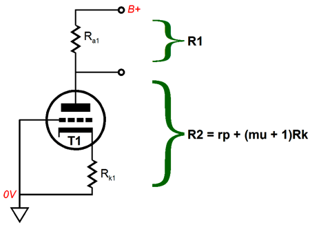
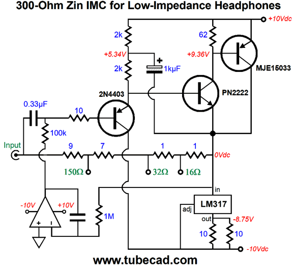
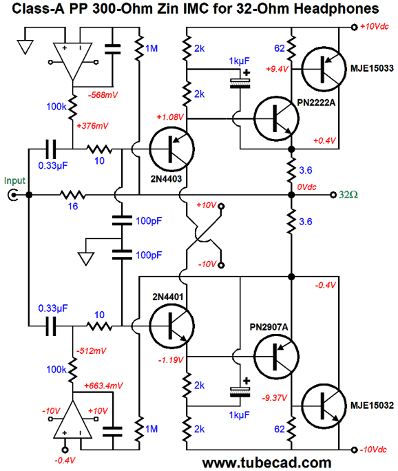
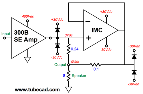
The two halves of the IMC work independently and in opposition to each other. Each uses its own "R2" resistor (3.6 ohms) to measure the current flow and to establish the impedance-multiplying ratio. Effectively, these two R2s are in parallel, which explains why the math might seem off base. In addition, the 3.6-ohm resistor value was picked to compensate for the IMC's failure to achieve true unity-gain output and its own output impedance. By the way, if the IMC moves beyond its class-A window of current flow, then the impedance ratio will no longer obtain. With an idle current of 100mA, the class-A window extends up to 200mA, which against 32 ohms equals peak voltage swings 6.4 volts, which in turn translates into 640mW of power. This was the simple schematic, here is the full schematic.
The 100pF capacitors are there to limit the high-frequency bandwidth. The 0.33µF input coupling capacitors impose a 5Hz -3dB low-frequency cutoff on top of whatever high-pass filter the tube-based headphone amplifier's own output coupling capacitor truncates the low-frequency bandwidth.
Single-Ended 300B and IMC
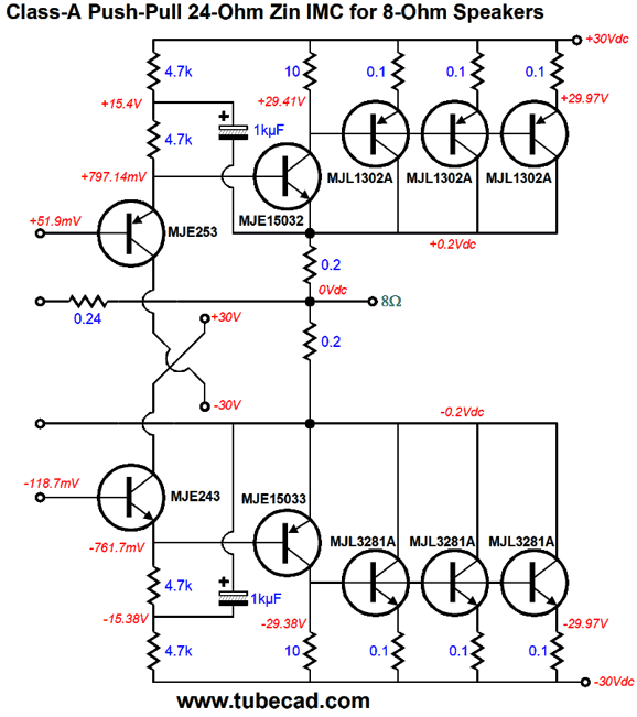
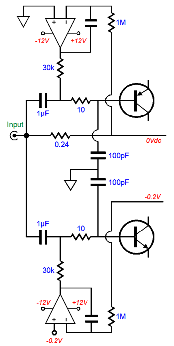
Well, that idea still haunts me and the class-A push-pull IMC shown above might be the best way to go. Of course, we will need +/-30Vdc power-supply rail voltages, not +/-10Vdc. In addition, we will need many more and more powerful output devices. The idle current would need to be half the expected peak flow; in this example, that would 2Apk, so 1A at idle. I like to limit power transistors to no more than 10W of heat production at idle, so six TO-247 power transistors would be needed per channel.
All the transistors are beefier than those found in the headphone version are. In addition, the two OpAmps can no longer just attach to the power-supply rails; thus, the +/-30Vdc bipolar power-supply rail voltages would need to be regulated down to +/-12Vdc. We could get extra fancy and add a Zobel network to the output and series damped inductor (a 2W 10-ohm resistor with magnet wire wrapped around its body and shorting its leads). Because the 300B power amplifier is transformer-coupled at its output, we need to worry about inductive voltage spikes. In other words, we should add "catcher" diodes to both the IMC's input and output.
With these diodes in place, neither the input voltage swings nor output voltage swings can much exceed the +/-30V bipolar power supply rail voltages. The IMC's frontend input coupling capacitors and DC servos will need some adjustments as well.
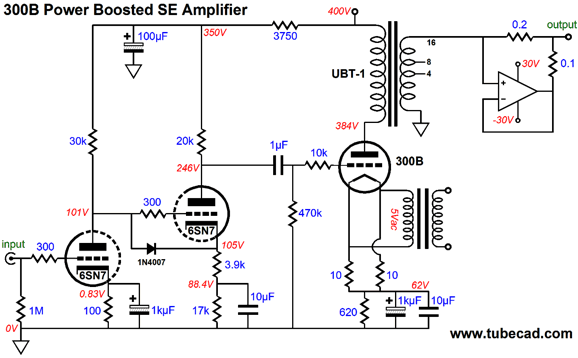
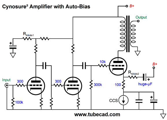
The coupling capacitor values have been increased to 1µF and the DC servo output resistor values reduced to 30k. Note the lower power-supply rail voltages for the OpAmps. The complete amplifier would require an input stage to drive the 300B output tubes and massive heatsinks. I would make monobloc amplifiers, long in depth, but narrow in width, with heatsinks at the left and right sides. I would use either the Aikido cascade circuit based on a single 6SN7 or an Aikido gain stage that used a 12AX7 input tube and a 12AU7 output tube.
Of course, I would add my Aikido single-ended output stage mojo, wherein the 300B's cathode gets an extra shunting capacitor that terminates into the B+ voltage. The output transformer would be the One Electron UBT-1, whose winding ratio between primary to the 16-ohm tap on the secondary is 10:1, which implies an impedance ratio of 100:1. In other words, the 24-ohm load presented by the IMC and the 8-ohm loudspeaker reflects back to the 300B's plate as 2400 ohms.
Music Recommendation: The Man Upstairs Tidal offers both this album and Jack Johnson's.
//JRB
User Guides for GlassWare Software
For those of you who still have old computers running Windows XP (32-bit) or any other Windows 32-bit OS, I have setup the download availability of my old old standards: Tube CAD, SE Amp CAD, and Audio Gadgets. The downloads are at the GlassWare-Yahoo store and the price is only $9.95 for each program. http://glass-ware.stores.yahoo.net/adsoffromgla.html So many have asked that I had to do it. WARNING: THESE THREE PROGRAMS WILL NOT RUN UNDER VISTA 64-Bit or WINDOWS 7 & 8 or any other 64-bit OS. I do plan on remaking all of these programs into 64-bit versions, but it will be a huge ordeal, as programming requires vast chunks of noise-free time, something very rare with children running about. Ideally, I would love to come out with versions that run on iPads and Android-OS tablets.
//JRB
|
|
I know that some readers wish to avoid Patreon, so here is a PayPal button instead. Thanks. John Broskie
John Gives
Special Thanks to the Special 79 To all my patrons, all 79 of them, thank you all again. I want to especially thank
I am truly stunned and appreciative of their support. In addition I want to thank the following patrons:
All of your support makes a big difference. I would love to arrive at the point where creating my posts was my top priority of the day, not something that I have to steal time from other obligations to do. The more support I get, the higher up these posts move up in deserving attention. Only those who have produced a technical white paper or written an article on electronics know just how much time and effort is required to produce one of my posts, as novel circuits must be created, SPICE simulations must be run, schematics must be drawn, and thousands of words must be written. If you have been reading my posts, you know that my lifetime goal is reaching post 1,000. I have 518 more to go. My second goal is to gather 1,000 patrons. I have 921 patrons to go. Help me get there.
Only $12.95 TCJ My-Stock DB
Version 2 Improvements *User definable Download for www.glass-ware.com | ||


| www.tubecad.com Copyright © 1999-2019 GlassWare All Rights Reserved |