| John Broskie's Guide to Tube Circuit Analysis & Design |
|
30 November 2020 Post 521 Updated March 09 2022
Class-G and Class-H The new spying rule became: only blueprints, documents, and photographs were of value; no interpretation would be allowed. Much like that spy-director, when I read the technical descriptions of audio gear in audio reviews, I don't want circuit interpretations or rehashed advertising copy, only schematics. But then, without the Murray Gell-Mann Amnesia Effect always holding sway, I would never read any audio magazine. What is the Gell-Mann amnesia effect?
I often encounter amplifier reviews that hold statements such as the following, "the second stage is a cathode follower that splits the phase so that the push-pull output stage can be driven," or "the 200W class-A amplifier only draws a modest 40W from the wall socket." Please, please let me see the schematic. I will do the interpretation, analysis, and appraisal of how the circuit works.
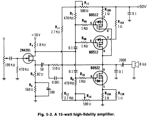
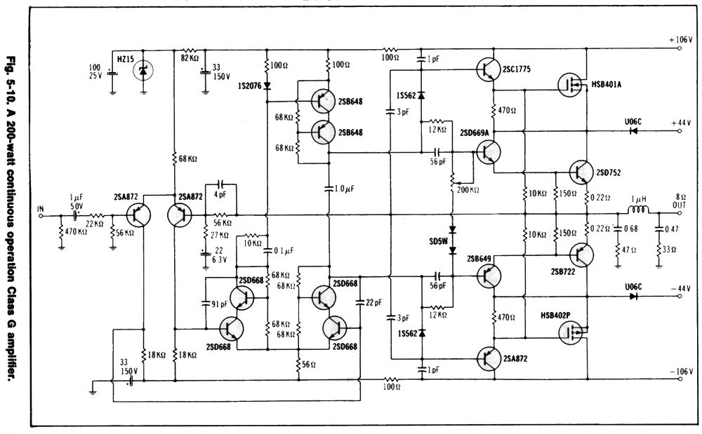
For decades now, Glass-H, unlike class-G, made no sense to me, as I only had audio magazine descriptions to study, no schematics. Forty years ago, I first encountered a class-G amplifier schematic in a great little book, Design of VMOS Circuits with Experiments, by Robert T. Stone and Howard M. Berlin. The book was written in 1980 and power vertical MOSFETs were the hot topic of the day. Filled with interesting audio circuits, such as a transformer-coupled single-ended 4W power amplifier that held two active devices, a small-signal FET and a power MOSFET, the book eclipsed all the audio magazines I was reading. In fact, the first MOSFET-based power amplifier I ever built was based on this design from the book.
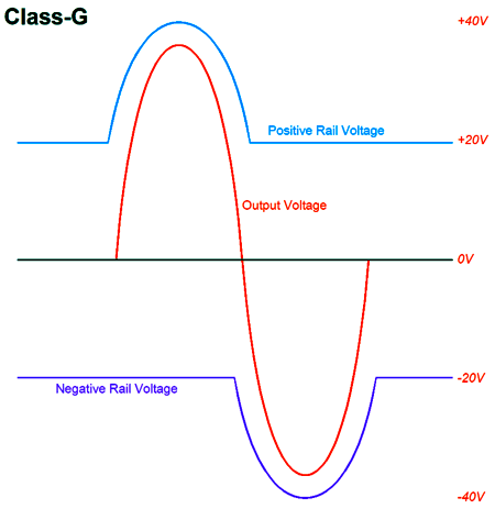
I feared current limiting and I desired a higher idle current, so I doubled the number of output MOSFETs and used a lower 44Vdc B+ voltage (in addition, the heatsink I used came with six pre-drilled holes for TO-220 mounting). The amplifier sounded far closer to a tube-based amplifier than a transistor-based amplifier. One problem, however, was that it was noisier than my other solid-state and tube amplifiers. (Today, I would make the necessary Aikido mojo inclusions.) Their book even showed a class-D amplifier that used MOSFETs in the output stage, but at the time I thought that there was no way the 2nd-order low-pass filter on the output could sound anything but turgid and thick in the highs, although it would probably make a great bass amplifier. The class-G amplifier the book showed was complicated, but it made perfect sense. A class-G amplifier was simply a class-AB amplifier that idled under a lower bipolar power supply voltages, but then experienced expanding rail voltages, as greater output voltage swings approached the lower rail voltages.
In contrast, descriptions of class-H amplifiers I had encountered in audio magazines were varied and confusing. The rough idea I formed was that a class-H amplifier somehow dynamically increased its bipolar power supply rail voltages due to increased voltage demands. One name for this arrangement I have seen is "envelope-tracking power supplies." I assumed that a TRIAC was used to vary the amount of the wall voltage that the power transformer saw at its primary. The only problem with this idea was that the 60Hz wall voltage was far too slow, as a crescendo might instantly appear, but the wall voltage could only slowly charge up its reservoir capacitors. Perhaps, I thought, the lag didn't much matter in a PA amplifier, which seemed to be the only widespread application that class-H amplifiers found.
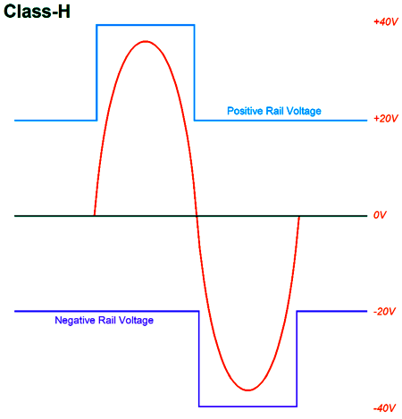
Then in audio magazines, I read that class-H amplifiers delivered a two-step power-supply rail voltage, that unlike class-G output stages, which delivered an expanding, linear rail voltage only a few volts higher than the output voltage, the class-H amplifier output stage switched between a low idle voltage and a high maximum-output voltage, say between +/-20Vdc and +/-40Vdc.
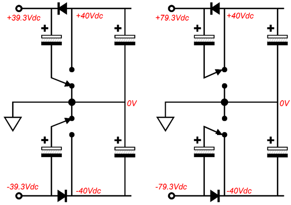
This some-and-more arrangement reminded me of a turbo charged car engine. (Actually, a supercharged engine is the better analogy, as the supercharger's kick works on the square of the engine's RPM; the turbocharger's, the cube of the RPM. If we double a power amplifier's output voltage swing, we get four times more power, not eight times as much.) One description I read stated that the advantage the class-H amplifier held over the class-G amplifier was that a single power supply could be used in a class-H output stage, as we could switch a power-supply reservoir capacitor's termination from ground to the B+ voltage to create a higher rail voltage on the fly.
The assumption here is that dynamic music is the input signal, not sustained sinewaves. Alas, today's highly compressed pop music comes closer to sustained sinewaves than a Beethoven symphony. How would the switching be accomplished? Relays are far too slow and can suffer from arcing. In contrast, transistors and MOSFETs can be switched on and off quickly and safely. (By the way, the new fourth-gen SiC MOSFETs look very promising.)
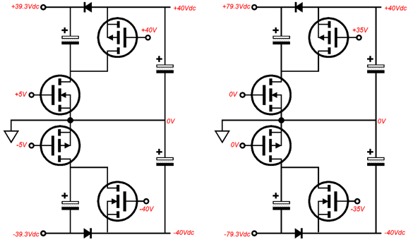
When the center MOSFETs are fully on and the top and bottom MOSFETs are fully off, the B+ voltage is 39.3V; in contrast, when the top and bottom MOSFETs are fully on and the center MOSFETs are fully off, the B+ voltage is 79.3V. Searching books on class-H amplifier topologies never yielded a schematic. In Douglas Self's book, Audio Power Amplifier Design Handbook, he describes class-H amplifiers thus:
G. Randy Slone wrote in his book, High-Power Audio Amplifier Construction Manual,
Earlier in his book, Slone explains how the urge to create more efficient power amplifier is misplaced, as the 50% efficiency of a class-A amplifier towers over loudspeaker efficiencies that usually fall between 0.05% to 1%. If loudspeaker efficiency was closer to 3% to 5%, we would be deliriously happy with 4W amplifiers. Note that Self and Slone flip the meaning of classes G and H, but Bob Cordell doesn't. As we all know to be a self-evident truth: an expert is someone who agrees with you. Well, in regard to classes G and H, Cordell is an expert. In his book, Designing Audio Power Amplifiers, he gives the following explanation.
Yes, he is right, as I have noted that the naming conventions are flipped in Japan and other countries, which apparently include England, based on the Self quote. Teemu Kyttälä's book, Solid-State Guitar Amplifiers, testifies the G & H confusion:
The most recent material I have read on class-H amplifiers was a white paper by Texas Instruments, Benefits of Class-G and Class-H Boost in Audio Amplifiers, SLAA888–April 2019, by Scott Bryson.
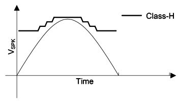
Yes, TI has made a class-H amplifier version of the class-D amplifier, but rather than doing the two-steps of power-supply rail voltage (which the paper names as class-G), they implement four steps (which TI views as being a jagged version of class-H operation; and people wonder why I drink).
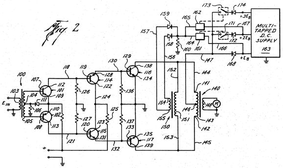
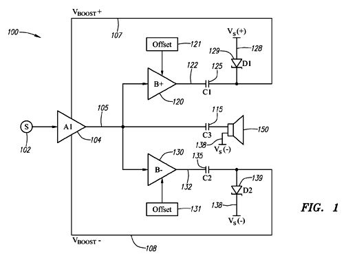
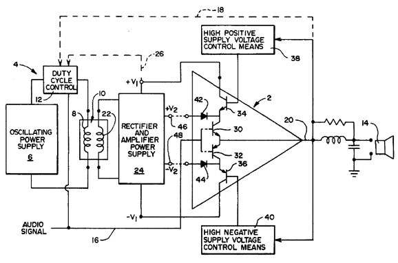
Yes, greater amplifier efficiency is a BIG DEAL in a cell phone or tablet, but not at all important to the average audiophile. If it were, we wouldn't see 1W 300B-based OTL amplifiers being made. I searched patents online and I found what appears to be the first class-H amplifier design and which begins in the most amusing way:
Wow! Are we suppose to salute, when reading this patent? The patent points out that:
Those were the days, when NASA was busy landing on the moon and designing high-end audio amplifiers. Alas, how we have strayed from the path…
Since the design is transformer-coupled, there is no reason that it could also be applied to tube-based amplifiers. Here is what the patent says:
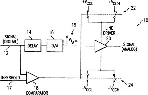
Compared to most patents, this is a startlingly clear exposition. A more recent patent was 2003's US 6,614,310 B2, by Texas Instruments, which details an amplifier with a digital input signal, which it then evaluates the expected peak output swings and implements a time delay before sending the data stream to an internal DAC. The result is that the amplifier sees the two-step power-supply rail voltages automatically, as the amplifier knew beforehand when the switching to the higher rail voltages would be needed. Clever.
Think about this, your power amplifier has no idea of what incoming signal is going to appear at its input. Your LP might skip or summon a big pop; you might scan through radio stations or play CD. In contrast, the digital amplifier knows what will be required of it, as it scans the ones and zeros before passing the data on to the DAC. In other words, it deals with a past event, not a present one. Imagine if you could buy stocks today, after having read tomorrow's Wall Street Journal.
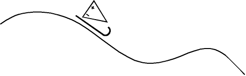
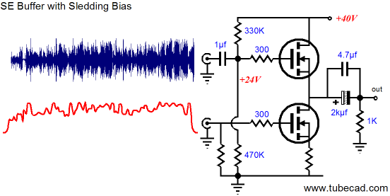
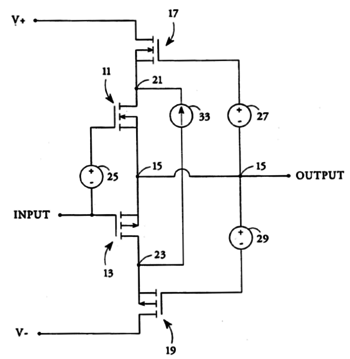
I am reminded of my idea of a sledding-bias, from posts 126 and 128. The idea was that since digital signal sources were effectively dead, we could perform an audio autopsy on the signal before passing it along to the power amplifier, whose idle current we would dynamically alter to meet the known and expected demands. My suggestion was that imbedded within the FLAC or MP3 digital file's header would be a map of expected peak current flows. The DAC would read this map and send out two analog output signals to the power amplifier, one of them the music signal and the other the slow-moving map content. As the crescendo approached, the amplifier's output stage would see its idle current increase before the crescendo arrives, the result being class-A amplification throughout, as none of the output devices would ever completely cut off. In the following schematic, we see a sledding-bias single-ended power buffer.
We could take this sledding arrangement one-step further and modulate both the amplifier's power-supply rail voltage and bias current on the fly, as the expected demands approached. What would happen if you skipped ahead to the next track? As the new map information was loaded, the amplifier's B+ voltage and idle current might be off for a second or two, as the new map was implemented—or a few-second pause would be required, as the amplifier reads the data and creates a map. An added subtlety would be for the sledding amplifier to read your current volume setting and normalize the map's values to it, so soft background playing would not waste the power that would be required for audiophile demos. Of course, a fast switching power supply would be needed to create the dynamic power-supply rail voltages and needed bias voltages. Another interesting patent was THX Ltd's 2014's US 8,723,605 B2, which detailed how two class-B amplifiers dynamically shift the bipolar power supply's rail voltages for the main power amplifier.
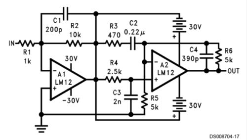
By the way, National Semi's LM12CL's 1999 datasheet shows how one amplifier can drive the other amplifier's power-supply rails.
Amplifier A1 sees a fixed bipolar power supply, while amplifier A2 sees a floating bipolar power supply, which amplifier A1 drives up and down to double effectively its rail voltages. This approach was used back in the late 1970's by Technics in their "Super Class-A" amplifiers. See post 449 for more details
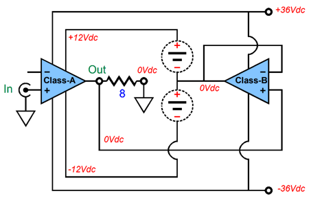
A class-B amplifier drives a class-A amplifier's power supply. See post 449 for more details
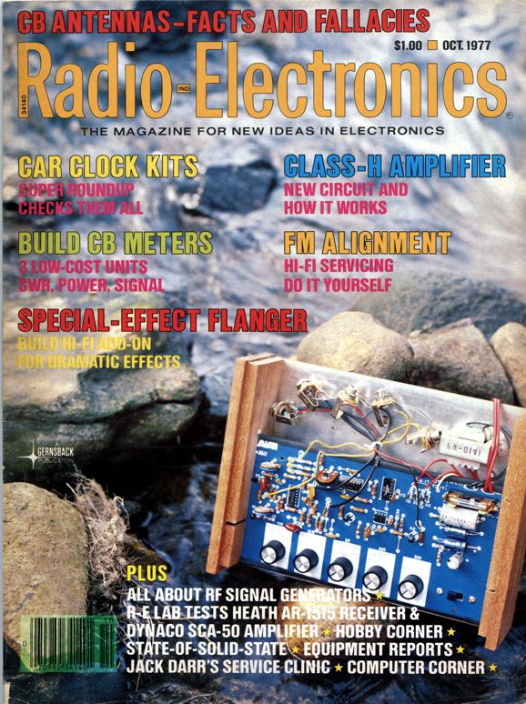
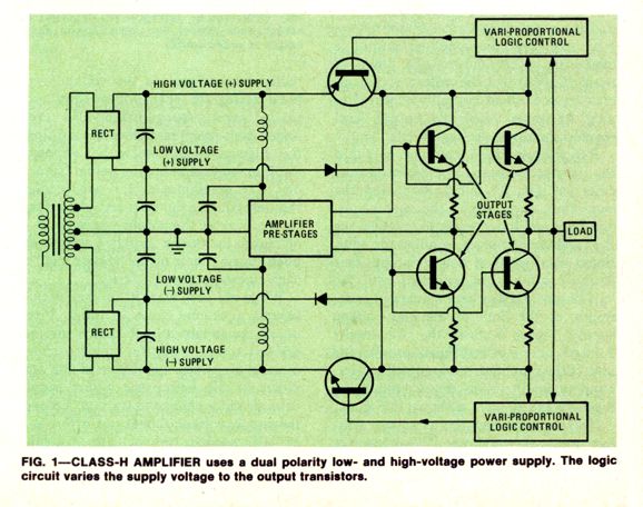
Well, I was reading an old copy of the late American electronics magazine, Radio Electronics, from October of 1977, when I came upon an article by one of my favorite electronics writers, Len Feldman, "Class-H Variproportional Amplifier." Hot dang. I finally got to see a schematic.
I grant that it looks confusing, but then so did the Rosetta Stone at first. Such an amplifier will require two bridge rectifiers, but not configured as shown. Complementary output transistors, i.e. NPN and PNP, could be used; moreover, I would have shown only two output transistors, for the sake of clarity. The LC filters formed by the inductors and capacitors that feed the amplifier's frontend are a nice touch. This leaves the switching transistors that expand the power-supply-rail voltages. Instantly, I was sure I could read the designer's mind. He or she wanted to overcome the harsh and abrupt switching glitches that the typical class-G amplifier experienced, as its switching transistors remained off at idle, whereas these common-emitter switching transistors could idle at a light current along with the main output transistors until they needed to fully switch on to raging current flows. A complete schematic drew itself in my mind. Once a trip voltage was met by the output, the required switching transistor would slam on, producing the two-step power-supply voltage. I was wrong.
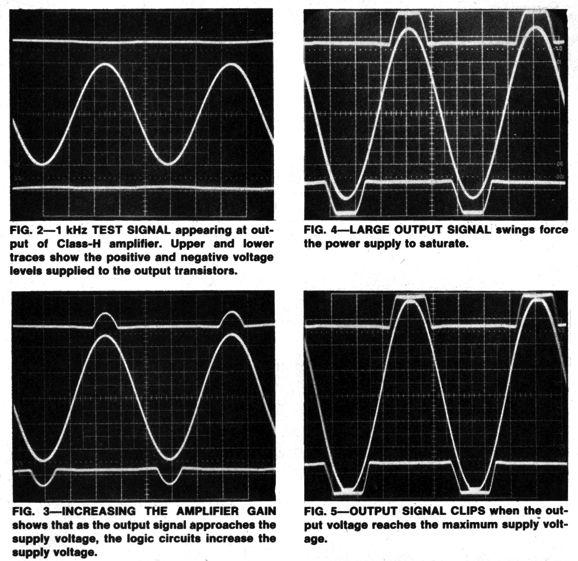
As I read the entire article and saw the many scope traces for the Sound craftsmen MA5002, the subject of the article, I realized that this was actually a class-G amplifier, as the expanding rail voltages linearly tracked the output voltage swings. My mental schematic erased itself. My trickle-flood arrangement needed to be replaced by something more elaborate, alas. Here is Feldman's conclusion:
My conclusion is that class-G topologies offer more potential than those based on class-H. In addition, it makes little sense to try to squeeze out a tad more efficiency from class-AB amplifier. Douglas Self pointed out that class-G would make far more sense with a class-A amplifier. In other words, a class-A amplifier would run the heavy required idle current for big watts, say 100W, which would equal 2.5A for a push-pull solid-state output stage; the amplifier's bipolar power supply, however, would provide only +/-16Vdc and, thus, only 80W at idle, not the 270W we would expect from a 100W class-A amplifier; as the output swing rises beyond the capacity of the +/-18Vdc power supply, the next power-supply rail of +/-32Vdc would engage; then, further along, the last rail of +/-48Vdc engages.
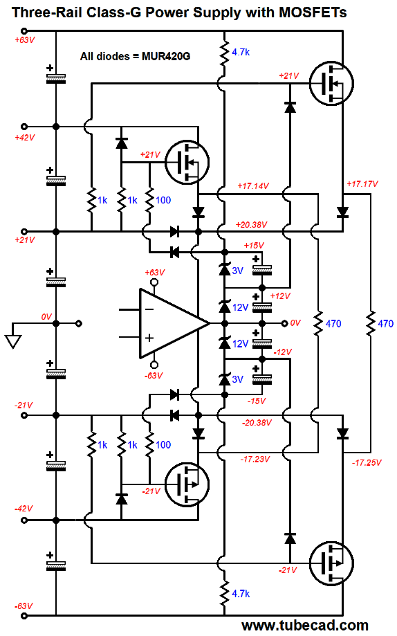
Three-Rail Class-G Power Supply
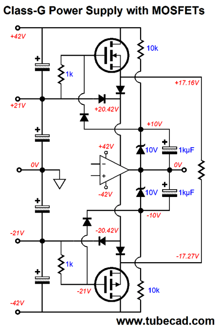
It's not as complicated as it might appear. Here is simpler, with only two sets of rail voltage, version.
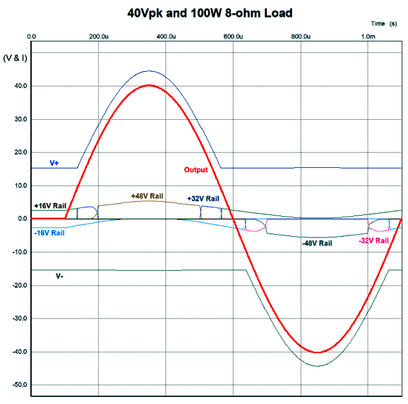
The class-A amplifier's input stage and VAS (voltage amplification stage) derive their power-supply rail voltages from the +/-48Vdc rails. At idle, the class-A amplifier power amplifier's power-supply rail voltage is only +/-18Vdc and its output stage draws 2.5A, while each MOSFET draws 60mA. As the output voltage swings up, the top zener will develop a voltage at its anode sufficient to trip the threshold voltage needed to forward bias the rectifier that attaches to it. Once this rectifier is forward biased, the MOSFET will begin to release a higher voltage at is source, which will eventually grow high enough to forward bias the rectifier at its source, causing the amplifier's positive rail voltage to climb with the rising output voltage, while at the same reverse biasing the rectifier that attaches to the +16V power-supply rail, thus decoupling the amplifier from that lower-voltage rail. The same happens in a negative direction, as the amplifier's output swings negatively. Engaging the third power-supply rails requires the two extra power MOSFETs and two extra zener diodes, which are needed to stagger the engagement of the MOSFETs, as we want the topmost and bottommost MOSFET to engage when the inner MOSFETs can no longer provide sufficient rail voltage to the amplifier. In other words, as the 40Vpk output sinewave completes is cycle, all six power-supply rails will have engaged sequentially, with small overlaps. None of the MOSFET will ever cease conducting, as the 470-ohm resistors always see a fairly fixed voltage drop. (Because the third rails will experience the greatest current flows, we might have to double up on their power MOSFETs. A 5A peak current flow is not all that big a deal to a modern power MOSFET, but a higher power output, say 400W, requires both 80Vpk and 10A peak, so at least two MOSFETs should be placed in parallel, possibly even more.)
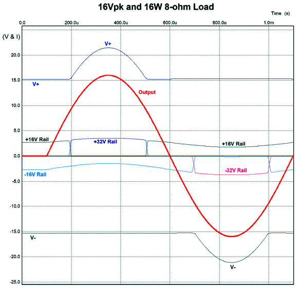
This SPICE-generated graph shows the current flow relations through the cycle at full output, i.e. 40Vpk into an 8-ohm load. You can see that the two 48V rails deliver the most current and for most of the cycle. With only 16W of output, the +/-48Vdc rails provide no current into the load. Now the +/-32Vdc rails do the heavy lifting.
By the way, if leave the 470-ohm source resistors out of the circuit, we end up with all the problems that most class-G amplifiers must contended with due to the transistors or MOSFETs switching off and then switching on, which gives rise to glitches and oscillations due to lead inductance and stray capacitances. Preexisting workarounds were klutzy extreme, often involving such band-aid fixes a chokes and snubber networks. The shared source resistor, in contrast, is a 50-cent solution. I thought I had found a prior-art example in Nelson Pass's 1994 patent, US5343166A. I was wrong. His patent dealt with cascode output stage, not class-G or class-H. Nelson showed how a floating power supply and constant-current source could feed the center MOSFETs a heavy idle current, while the top and bottom MOSFETs ran off a far lower idle current, which would further both low distortion and higher efficiency.
See post 554 for more details.
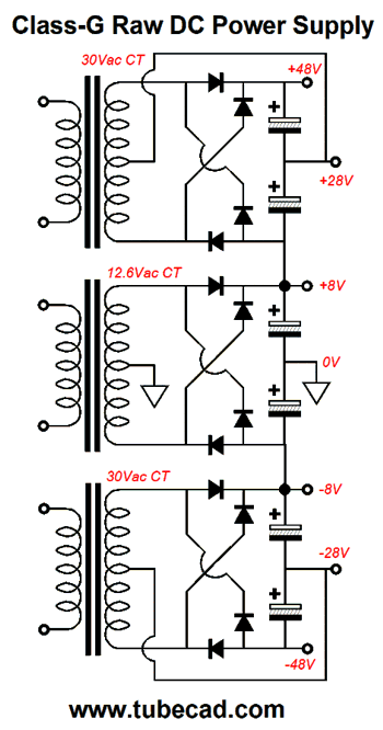
Let's return to the idea of a 100W class-A/class-G amplifier that runs of three sets of bipolar power supply voltages. We naturally assume equal voltage divisions between the power-supply rails; and of course, they need not be. For example, we could run dissimilar voltage jumps, such as +/-8Vdc, +/-28Vdc, and +/-48vdc. This array of voltages would greatly reduce the heat generated at idle, for at idle the 2.5A current flow produces only 40W of dissipation from the output devices. The first few watts of power output will be powered by the +/-8Vdc power-supply rails; thereafter, the second tier power-supply voltages kick in, and then the third power-supply rails engage. The result is something very close to Nelson Pass's cascode output stage, as after the first 6Vpk of output voltage swing, the output MOSFETs will see a fixed source-to-drain voltage. Here is what a one possible raw power supply would look like.
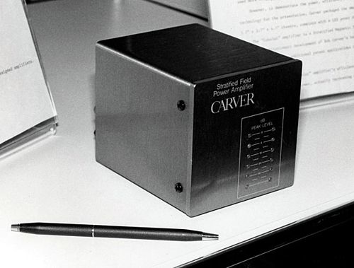
The remaining question is, What do the VA rating need to be for each power transformer? I would use 100VA for the center transformer and 300VA for the outer transformers. In other words, this would still be a massive power amplifier. We haven't cheated physics in any way. We must pay for every class-A watt we get. We will pay in transformer heft and in heatsink size. This would not be one of the old Carver magnetic-field power amplifiers that a child could hold in one hand.
Speaking of the old Carver magnetic-field power amplifiers, they were technological wonders. I marveled at the prodigious bass they could summon. Most of my audiophile friends foolishly scoffed at them. Why? Craver wanted to deliver Ferrari performance at Fiat prices.
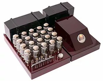
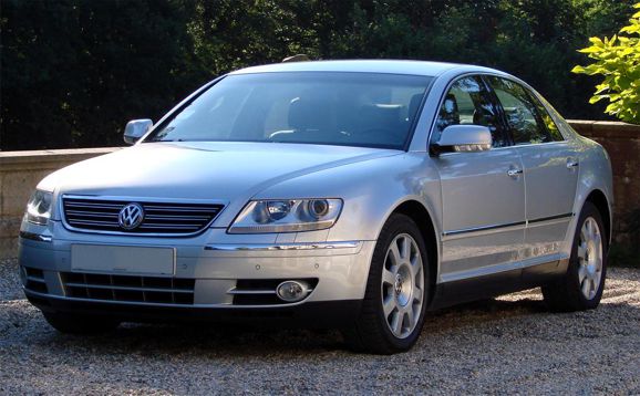
Today, he makes Ferrari-grade tube-based amplifiers at Ferrari prices. Had he renounced his populist passions and produced Ferrari amplifiers from the start, based on his magnetic-field power amplifiers designs, he would have made less money, but gained unsurpassed high-end-audio status. Long ago, I was often asked what I thought of Bob Carver. My answer was that I thought he was brilliant and one of my heroes, but that he had missed a prime marketing strategy, i.e. start at the high-end before you sell at the low-end, as brand cachet, prestige, reputation can pour down, but never up. The Volkswagen Phaeton is a good example of the unidirectional flow of status. The car was Volkswagen's first high-end luxury sedan, meant to compete against the German prestige brands of BMW and Mercedes-Benz. It flopped. As far as the public was concerned, it was still a Volkswagen, albeit a very nice VW, but not worth $95k, even if it held a twelve-cylinder engine and did 186MPH.
In contrast, Mercedes-Benz made and still makes budget cars, which carry a higher price tag due to the status of the high-end Mercedes-Benz cars pouring down. Status is everything. As Nassim Nicholas Taleb has pointedly asked, Have you ever met a Harvard graduate who didn't let you know he was a Harvard grad in the first 10 minutes of meeting him? (Actually, I have met one and only one exception: my wife.) Every Mercedes-Benz owner I have known has always referred to his car as "his Benz" or "his Mercedes," never as "my car." For example, "My damn Mercedes had flat tire yesterday." As I remember from having read a white paper from Carver Inc. that Craver's amplifier used a TRIAC to regulate the AC voltage going into the power transformer's primary, which in turn resulted in regulated power-supply rails, of which there were three, say +/-30V, +/-60Vdc, and +/-90Vdc. He then used some class-G/class-H arrangement to switch between the three voltages. The result was an insane amount of watts, as in 800W or more, but the amplifiers weighed no more than a 30W solid-state power amplifier. The assumption behind his amplifiers was that we listen to only a few watts on average with occasional huge peaks, which require brief bursts of hundreds of watts. As a result, smaller transformers, capacitors, and heatsinks could be used. In other words, his amplifier could not drive a shaker table for an hour at full output. Had Carver gone all-out, high-end at first, his amplifier would have held a 50lbs power transformer and beer-can sized capacitors and massive extruded heatsinks—and it could have driven that shaker table for an hour without sweating. Later, he could have sold his smaller and less expensive amplifiers—at a higher price, as the luxury status would have poured down and over them.
The more I think about the Carver magnetic-field power amplifiers, I zero in at the relatively small heatsinks they used. I haven't done the math, but it's possible the class-A/class-G amplifier arrangement might allow a far smaller heatsink than we might imagine. In fact, we could optimize for the smallest possible heatsink that still allowed 100W of class-A output, by mathematically setting the optimal three (or more) power-supply rail voltages. So many ideas, so little time.
Music Recommendation: Paul Lewis If you have only heard the orchestrated version of Mussorgsky's piano composition, you are in for a treat. Of the orchestral versions, French composer Maurice Ravel's 1922 version is the one most often performed, but other translations exist by other composers, such as Sir Henry J. Wood (1918), Leopold Stokowski (1939), and Vladimir Ashkenazy (1982). If you haven't heard Stokowski's version, hunt it down, as it is fun listen, especially the 7th movement, "Ballet of the Unhatched Chickens." //JRB
User Guides for GlassWare Software
For those of you who still have old computers running Windows XP (32-bit) or any other Windows 32-bit OS, I have setup the download availability of my old old standards: Tube CAD, SE Amp CAD, and Audio Gadgets. The downloads are at the GlassWare-Yahoo store and the price is only $9.95 for each program. http://glass-ware.stores.yahoo.net/adsoffromgla.html So many have asked that I had to do it. WARNING: THESE THREE PROGRAMS WILL NOT RUN UNDER VISTA 64-Bit or WINDOWS 7 & 8 & 10 or any other 64-bit OS. I do plan on remaking all of these programs into 64-bit versions, but it will be a huge ordeal, as programming requires vast chunks of noise-free time, something very rare with children running about. Ideally, I would love to come out with versions that run on iPads and Android-OS tablets.
//JRB
|
|
I know that some readers wish to avoid Patreon, so here is a PayPal button instead. Thanks. John Broskie
John Gives
Special Thanks to the Special 90
I am truly stunned and appreciative of their support. In addition I want to thank the following patrons:
All of your support makes a big difference. I would love to arrive at the point where creating my posts was my top priority of the day, not something that I have to steal time from other obligations to do. The more support I get, the higher up these posts move up in deserving attention. If you have been reading my posts, you know that my lifetime goal is reaching post number one thousand. I have 479 more to go. My second goal was to gather 1,000 patrons. Well, that no longer seems possible to me, so I will shoot for a mighty 100 instead. Thus, I have 10 patrons to go. Help me get there.
Only $12.95 TCJ My-Stock DB
Version 2 Improvements *User definable Download for www.glass-ware.com |
||


| www.tubecad.com Copyright © 1999-2020 GlassWare All Rights Reserved |