| John Broskie's Guide to Tube Circuit Analysis & Design |
Gomes & SE+ & Error Take Off |
||||
04 Demember 2004 Gomes amplifier It turns out that I got quite a few things wrong: first of all, Jose Gomes's name is not spelled "Gomez." A thousand apologies. Second, his circuit uses a single bypassed common cathode resistor for the bottom triodes. 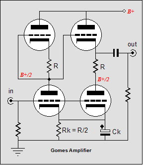
How much of a difference does this change make? If I remember correctly, it only slightly increased both the gain and the distortion. I will run a new set of tests to find out. The Gomes amplifier looked familiar to me in spite of not having read the L'audiophile article. I went digging in my own experimenters notebook and found this circuit.
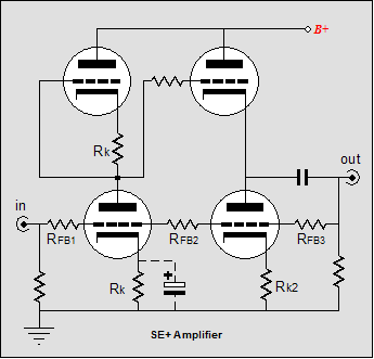
SE+ amplifier At first glance, this amplifier looks quite similar to the Gomes circuit; it isn't. The Gomes amplifier is an unbalanced push-pull amplifier, whereas this amplifier is single-ended throughout. The cathode follower is loaded by a wimpy-quasi-constant-current source (its cathode resistor is too small to make any real diference) that does not see any of the input signal. 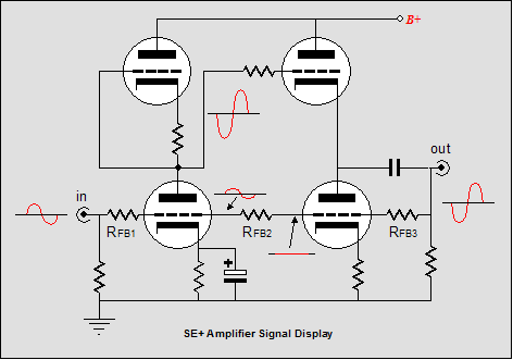
The schematic above shows the signal relationships throughout the circuit. The input is amplified and phase inverted at the output. The three feedback resistors divide the signal at two points: the signal at the input tube’s grid and at the output stage’s bottom triode’s grid. Not that a small portion of the input signal persists at the input tube’s grid, whereas the following triode sees only the null between the positive input signal and the negative output signal. If this triode sees no signal, why not just ground its grid? The answer is that if the amplifier added no distortion, then that would be the best layout. However, all amplifiers distort. If you look at the schematic below, you’ll see the distortion-product relationships throughout the circuit. The input is assumed to be distortion-free and to offer no output impedance. Thus, the circuit’s distortion is voltage divided twice by the three feedback resistors. Notice how the output stage’s bottom triode’s grid now sees a signal, a bigger signal than the input triode sees, in fact. Our active load has now become aggressive and it works to cancel the distortion at its grid. This is where the "plus" enters the name. 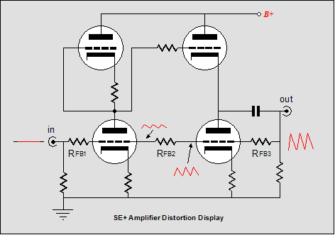
How well does this circuit work? In a test bench setup, I was able to get a deep null in distortion, but only after tweaking the circuit a bit. Quite a bit, actually. I found that the cathode follower’s triode needed a small-valued cathode resistor to give the bottom triode a better load to bite on. Below is the test-bed circuit I used, which allowed quick part value altering. 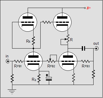 SE+ test setup After much tweaking, the lowest distortion was realized by the following circuit: 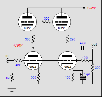
Using 6922s, I was able to get as little as 0.01% at 1V into 300 ohms. Therefore, I was enamored of the circuit, right? Well, no. I wanted to stick to pure single-ended operation and here a bit of push-pull operation had snuck in through the backdoor. Furthermore, the null was tube sensitive; a different 6922 did not equal an equally low distortion figure. In addition, I was troubled by the higher output impedance. Still, I think that this circuit is worth experimenting with. The road to SE+ As I have written here before, I had faced a long walk to work and I needed something better than the puny amplifier in my portable CD player to drive my 300-ohm Sennheiser HD-580s. I assumed that the amplifier would have to be solid-state, as I did not want to haul a car battery on my back. I also wanted to fit all the circuitry into a small metal box, like the Altoids tin (I think I would’ve used a Penguin mints tin instead—a more caffeinated sound would result, I’m sure.) The small box could hold two-channels worth of circuitry and one 9-volt battery, but not two. Thus, I tried to come up with a way to split the 9 volts into ±4.5 volts. 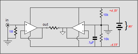 In the schematic above, we see two OpAmps, one working as an amplifier, the other as a virtual ground. The two 10k resistors define a voltage divider that splits the 9 volts in half and, thus, defines the “ground.” The 0.1µF capacitor may not be needed, but since most OpAmps suffer from a dissimilar PSRR figure for positive and negative power supply connections, the negative usually being about 20 dB worse than the positive, the capacitor added a little insurance. The virtual ground is meant to be shared between channels and need not use an OpAmp, as a buffer IC would work just as well, if not better; this buffer could be the lowly LM310 or something hotter, such as, the LT1010CN8. Well, that’s how the plan started. I then wondered if each channel should get its own virtual ground. Two OpAmps or two buffers could have their outputs shorted together, with a 10-ohm resistor in series with each output. This would work, but the added resistors troubled me, so I wondered why not give each channel its own independent ground, as that would also allow easy phase reversals. Of course, headphones don’t come with two plugs, but splitting the wires and adding plugs would be easy enough. Sandman's "error take off" scheme
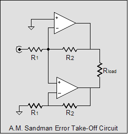
The top amplifier is inverting and its gain is defined by the ratio between resistors R1 and R2, Gain = R2/R1. For example, if R2 is ten times larger than R1, the gain will be ten. The bottom amplifier is a non-inverting amplifier that has a gain equal to (R2 + R1)/R1. For example, if R2 is ten times larger than R1, the gain will be eleven. Assuming that each amplifier possess infinite open-loop gain, the bottom amplifier would never see any signal, as its input is the null point between the top amplifier’s feedback loop. Thus, the bottom amplifier would work merely as a virtual ground; until distortion is added to the mix, that is.
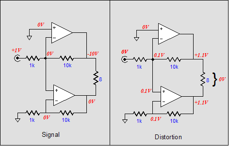
In the schematic above, two views are presented. On the left side we see how an input signal would propagate through the circuit; on the right, distortion. The distortion side is the more interesting. Here we see 1.1 volts of distortion at the top amplifier’s output. This distortion is not present in the input signal, so the two feedback resistors voltage divide the distortion to one eleventh of it original value. The bottom amplifier then receives this 1/11 worth of error signal and amplifies it by elevenfold. The result is that the loudspeaker sees the signal from both amplifiers; but as the signal is equal in magnitude and in phase, the loudspeaker never experience any net current flow across its voice coil; thus, no sound. Brilliant, but expensive. Two amplifiers-worth of parts and beefed-upped power supply is quite a price to pay for reduced distortion. Still, the whole point of this journal is tube topology, not tube accountancy. Mr. Sandman realized that this would be a common complaint, so he offered several variations on the error-take-off scheme. Consider this: even in the dirtiest amplifier, distortion is a small percentage of the output. So why use equally powerful amplifiers to vanquish distortion, when a smaller, less powerful, but cleaner amplifier can clean up the mess left by a bigger, dirtier amplifier. Below we see Sandman’s iterative circuit. 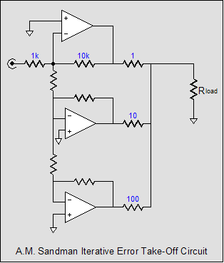
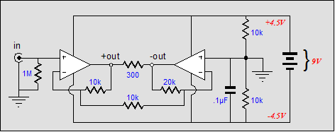
Each cascading amplifier receives the distortion from its preceding amplifier and works to cancel it at its output. Three amplifiers are shown, but many more could be used, each being less in power than the preceding. (Note the increasing in value series resistors at each output. This would imply that each succeeding amplifier would have to have an ever greater gain than the preceding.) By the way, this arrangement is somewhat similar to the Quad current dumping scheme, but not exactly. Before the tube fanciers lose heart from seeing too much silicon, I should point out that Sandman’s error-take-off scheme is not limited to solid-state amplifiers—tube amplifiers could just as easily be used. Imagine a class-B, pentode-based, push-pull amplifier, one that sported four 6550s and a high-voltage power supply. Such an amplifier could easily put out 200 watts, 200 fairly-dirty watts. Now, imagine a class-A, triode-based, push-pull amplifier, one that sported two triode-connected EL34s and a medium-high-voltage power supply. Such an amplifier would put out only 10 watts, 10 fairly-clean watts. And, finally, imagine a class-A, triode-based, single-ended amplifier, one that sported one 12B4 and a lower-high-voltage power supply. Such an amplifier would only put out 1 watt, 1 clean watt. Each cascading amplifier would further refine the output signal. (I can hear the grumbling: What a tasteless idiot this guy is. Who would use 6550s, El34s, and 12B4s? Ok. Imagine four 211s, two 300Bs, and one 45.) Some whining For the remaining 1% of us, the readers of this journal, my recommendation is to seek out articles like Mr. Sandman’s and see what is common in the seemingly different. For example, why not build a Quad-like current-dumping amplifier with tubes? Or, why not look into US patent number 2748201 by McMillan for some ideas? Back to Altoid tins The best solution I found, other than using two 9-volt batteries, was to create a bridge amplifier out of two OpAmps. This arrangement effectively doubles the output-voltage and current swing over a single OpAmp and it was amazingly easy to implement, as shown below.
Notice how the unbalanced input signal is balanced at the two outputs and how the feedback loops do not require the usual coupling capacitor to ground. Ok, so what’s wrong with this circuit? Each OpAmp now effectively sees a 150-ohm load, which is a bit much for most OpAmps. The NE5532s would work, but I hate the dead sound they make. The best solution might be to add a buffer stage to each output (I would use discrete transistors). //JRB
|
Only $12.95 TCJ My-Stock DB TCJ My-Stock DB helps you know just what you have, what it looks like, where it is, what it will be used for, and what it's worth. TCJ My-Stock DB helps you to keep track of your heap of electronic parts. More details. Version 2 Improvements *User definable Download or CD ROM |
|||
| www.tubecad.com Copyright © 1999-2004 GlassWare All Rights Reserved |
