| John Broskie's Guide to Tube Circuit Analysis & Design |
|
19 March 2018 Post 416
Back to OTL Designs
Imagine that you not only want music piped into every room of your house, but supremely fine wine, both red and white, just a spigot turn away from oenological rapture. So, you set about building in the walls of your house an elaborate system of refrigeration, tubing and pumps. For tubing you decide to use the three or four 100-foot garden hoses in your backyard. The big day arrives and you feel like James Bond, as you turn the handle and pour your first glass of Grand Cru in your bedroom. Once you are done with the spitting and the disgust, you wonder what went wrong. You bought the highest-rated bottle of wine that S400 could buy; you bought a new set of wine-appropriate Riedel wine glasses; what else could you have done? Like so many audiophiles who fret over the six-foot power cable, but do not give any consideration to the hundred feet of Romex AC wiring inside the walls, you forgot about the lawn hose. Well, output transformers and output coupling capacitors are like the garden hose. Look at the power transformer next to the output transformer. Usually, they are the same size, but they shouldn't be. Why not? Don't they deliver the same amount of power? The power might be the same, but the frequency isn't. Here in The States, our wall sockets put out 60Hz AC. Music goes, however, far lower than this frequency. Is this a problem? Yes, indeed, for transformers every halving of output frequency at full output requires a four-times bigger output transformer. If our wall voltage came into our houses at 120Hz, all the power transformers throughout our house would be much smaller. Iother words, if we want full-power bandwidth down to 15Hz, then the output transformer must be truly huge. Okay, why not just make a bigger output transformer? The problem with a huge output transformer is that it costs a bundle to make and to ship.
An output coupling capacitor faces the problem of having to be large enough in value. How big is needed? If we wish to go down to 10Hz with 4-ohm loudspeaker, then we a 4,000µF coupling capacitor. In a car stereo, with a 12V B+ voltage, we could use a 16V, 3.9kµF electrolytic capacitor and be happy with both its cost and size. With tube power amplifiers, this coupling capacitor might have to be rated for 200V, which means that it isn't even made and if it were made, it would be huge. Assuming it were an electrolytic type, it would be mammoth; if it were a film or PIO coupling capacitor, then it would be monstrously, insanely huge, say as big as an 50-gallon oil drum.
Well then, why we don't we just direct-couple the tube output stage to the loudspeaker aka an OTL output stage? Two reasons: vacuum tubes are current limited and DC coupling is supremely dangerous. Compared to MOSFETs and bipolar transistors, tubes present far too little transconductance and far too much internal resistance to happily directly couple to a 4-ohm loudspeaker. What speaker impedance would they prefer? A good starting impedance would be 600 ohms. (In fact, they used to make 600-ohm loudspeakers for radios.) The output transformer saved the day by providing an impedance matching function, where the output tubes' tiny current flow and large voltage swings got translated at the output transformer's secondary into big current and tiny voltage swings. The loudspeaker might be a 4- or 8- or 16-ohm load, but as far as the output tubes were concerned it was 3,000 ohms. Tubes require high-voltages to deliver heavy current, which results in power-supply rail voltages of +/-140V or more in an OTL amplifier. If a power tube arcs, then the speaker will be connected to 140 volts until the fuse blows or the woofer voice-coil melts. True, arcs are rare, but tube warm-up times are not. As the direct-coupled tube amplifier warms up, its output tubes may differ in conductance, which will introduce a DC offset that can be in the tens of volts, before the amplifier finally stabilizes. An output coupling capacitor will protect the speaker. True, a protection relay could be used, but it would require a complex driving circuit. Remember: the more you add to an amplifier, the more that can go wrong. A third way out exists: the autoformer, which is like an output transformer with only one winding. Autoformers offer many advantages, such as being half the size as an equivalent transformer for the same power delivery and providing less DCR and wider bandwidth, but they also provide added safety. Imagine a loudspeaker attaching to an OTL output stage through an autoformer; an output tube might arc and then melt into a direct short, yet the loudspeaker is safe, in spite of the 140V power-supply rail it attaches to. How is that possible? The autoformer's single winding is simply a long length of coiled wire, wire which offers an extremely low DC resistance. Thus, the loudspeaker is effectively shunted by a few milliohms of resistance, so even if the wire eventually melts, the speaker's resistance being thousands of times higher, sees thousands of times less current.
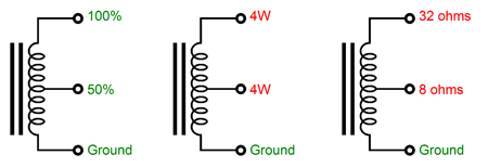
So, it looks like we are stuck with either using an output transformer or a coupling capacitor or a relay-protected DC coupling. If I had access to the inside of an output transformer factory, I would make an output transformer for OTL amplifiers. Yes, I know that output transformers and OTL are a paradox. Well, it's a paradox if you are the forgiving sort; and a contradiction or falsehood, if you are less forgiving. The fault is mine, I am thinking solely in terms of topology, not in marketing—or even truth in advertising—terms. The famous totem-pole topology of the Futterman OTL or the circlotron topology is what I have in mind.
Given either of these topologies, I would love to make a 100W output transformer whose primary reflected 32 ohms. This transformer would hold a winding ratio of 2:1 from the primary to the secondary's 8-ohm tap; a 2.8:1 ratio, the 4-ohm tap; and a 1.4:1 ratio, the 16-ohm tap. Such an output transformer would most likely offer fantastic high-frequency bandwidth, due to the low winding ratio. Achieving low-frequency extension require lots of iron. But as such a transformer would be intended for push-pull use, so no air-gap would be needed, allowing it to be smaller than a transformer intended for single-ended use. Would a 32-ohm make that much a difference? Let's do the math. Say that our Futterman or circlotron OTL amplifier is cable of delivering a safe and sustained 3Apk of output current swing. We square the current and multiply it against half of the load impedance; in other words, 3² x 8/2 = 36W. (Now, as many high-end audio companies seem to have reverted to peak watts, which are twice the value of average or "RMS" watts, so they would describe this OTL as being a 72 watter. Not every maker of high-end audio, it seems, wants to go to heaven.) But with the 2:1 winding ratio, we get twice the peak current flow at the secondary's 8-ohm tap, so we get 6² x 8/2 = 144W. The assumption here is that the OTL amplifier is only current-limited, not voltage-limited, which is usually a safe bet, but not always. For example, to get a peak current flow of 3A into a 32-ohm impedance requires a peak voltage swing of 96V.
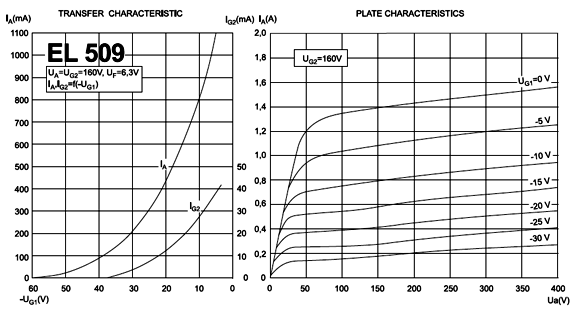
With EL509 horizontal sweep pentodes, this much voltage swing is probably not a problem; the graph above shows that one EL 509 can deliver 1A of current flow with only 40 volts of cathode-to-plate voltage, so three in parallel, a total of six per channel, would deliver 3A into the 32-ohm load. With a 6AS7 or 6C33 triode, in contrast, the bipolar power-supply rail voltages would have to be much higher than usual. A quick cheat is to divide the positive rail voltage by the triode's plate resistance to see what its safe peak output current swing would equal into a dead short to ground. A 6AS7's plate resistance is 280 ohm, so with a positive rail voltage of 112Vdc, we get 400mA per 6AS7 triode (it is a dual triode tube), so a total of eight 6AS7 tubes would be needed per channel. Alas, we are not done, as we must add the 96V of voltage swing to the bipolar power-supply-rail voltages, bring them up to +/-208Vdc. Of course, we could aim for lower power output or use more triodes in parallel to lower the rail voltages. The easy formula is: Vps = Ipk(rp + Rload) This formula gives us the needed bipolar rail voltage. If a mono-polar power supply is used, as was the case with the Futterman OTLs, then the single B+ voltage must be twice this value.Math is mean. By the way, I am a famous mathematical party pooper. Here is one of my favorite examples. Decades ago, a buddy of mine told me that he would love to get married, if he could find the right woman. I asked him what requirements his future Mrs would have to meet. His list was long, so I broke out pencil and paper and calculator. She had to be white, tall, thin, blonde, blue-eyed, an IQ of at least 140, hold a Ph.D., be between 26 and 30 years old—and a babe. Believe it or not, he wasn't already married.
We lived in California, so he had a potential pool of females of about 15 million to choose from. I then pointed out that only 15% of those females were born-blonde, so he only had 2,250,000 women to chose from; then I pointed out that only 25% of the California population had blue eyes, so he was now down to 450,000; then I pointed out that only one in 400 has an IQ between 140 to 145, so he was now down to 1,125 women; then I pointed out that less than 2% held a doctorate degree, bringing his total down to 22.5; the percentage of women in his age group was roughly equal to an 80-year life span divided by his 4-year range, or 1 in 20, dropping his number to 1; but it was worse than that, as about a third of women that age were already married and I didn't factor how many were lesbian or too short into the equations. I told him that now that he had a better grasp on the reality of the situation, he could happily forget about ever getting married. I cheated. It is so easy to do. It happens all the time in social studies. For example, a city raises its minimum wage to $50 an hour. Two years later, an economist interviews the city's business to see if the increase in pay was a burden. He learns that although it was tough going, it wasn't that bad. The smartest people in the room are delighted by the scientific results, so they ponder a $60 an hour minimum wage. What went wrong? You can only interview the businesses that survived, not those that folded or moved to a less insane city. This is called survivor bias, as only survivors can answer questionnaires. With my buddy, I got many twofers. For example, if someone was born blonde, then she is likely to also be blue-eyed and white. If someone holds a PhD, then she is likely to also have a high IQ. There is even a small positive correlation between height and intelligence, as was found recently by researchers at Edinburgh University and which was one of the conclusions of the Terman Study of the Gifted. Indeed, the fact that he and I were holding our conversation in the heart of Silicon Valley upped his odds of finding his other half nearby, as 13% of Palo Alto's population holds a PhD. So after a fairer mathematical analysis of his odds, there were probably 200 women that would qualify.
But that is not what I told him; no, I was so rude that I pointed out that even if he were so lucky to meet a woman who met his high standards, why should she be in the least interested in him?
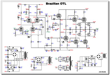
Brazilian OTL
Where to start? When designing preamps, start at the beginning; but when designing power amplifiers, start at the end. Luis had specified four Russian 6C33 output tube per channel in a totem-pole arrangement with a bipolar power supply, and the output would be coupling-capacitor-free. The 6C33 is an amazing tube.
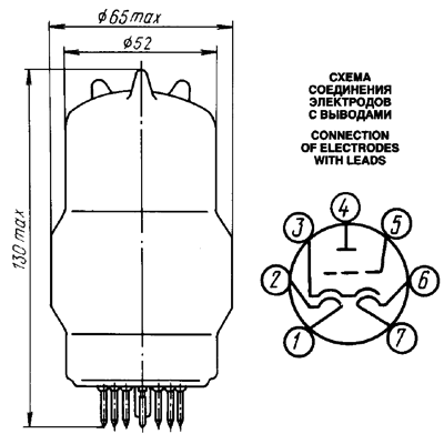
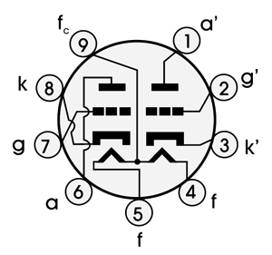
First of all, it doesn't look like any other output tube and it requires an odd tube socket and 3.6A of heater current at 12.6V. It was designed to function as the pass device in high-voltage series voltage regulators. Its electrical specifications are impressive, such as its 60W plate dissipation rating and its 600mA plate-current rating. Its plate resistance is a low 120 ohms and its transconductance falls between 30mA/V to 50mA/V. On the downside, the cathode can take up to 2 minutes to heat up and the tube is famous for proving squirrelly. I remember reading a good article on output tubes that was written either in the late 50s or early 60s. The author came up with a system of evaluation that resulted in a figure of merit, which was based on cost, heater current draw, linearity, transconductance, plate dissipation and cathode current limits. (Of course, we have advanced far beyond his system today, so a current list for evaluation would consist of far more important characteristics such as cost [the higher the better], drive, slam, pacing, bloom, jump factor, sparkle, and snob appeal.) If I remember correctly, the little EL84 offered the highest figure of merit. Well, I do a much simpler evaluation: I ask how much heater wattage is required per 1A of cathode current flow in an OTL. I should make an Excel worksheet to array all the current output tubes and see which comes out on top. If I were a betting man, I would place my bet on the EL509. (By the way, the JJ version does not use an anode cap and takes the plate connection at a base pin, along with grid, screen, and heater connections.) In SPICE simulations, bipolar power-supply rail voltages of 140V worked well.
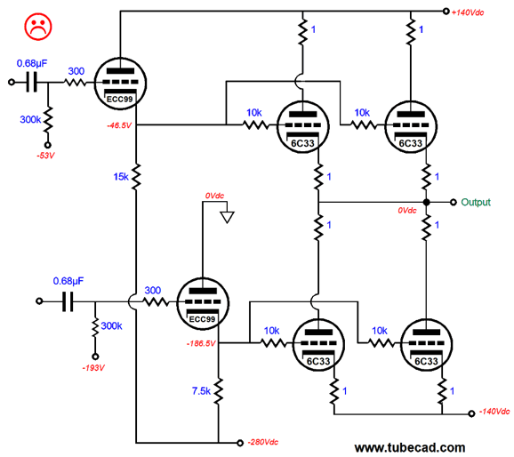
Missing from the schematic is an output relay, but not the plate-stopper resistors. Stepping back one step from the output, we have to decide on whether to use coupling capacitors or cathode followers to connect to the 6C33 grids. Since the tube will be driven hard and will probably enter positive grid bias, the safest choice is the cathode follower coupling.
The cathode followers are then capacitor coupled to the phase-splitter stage. Why the sad face? Well, although 99.9% of tube gurus wouldn't label this circuit with a sad face, the huge problem that I see is that the two cathode followers do not work in a symmetrical or a balanced fashion, as the top cathode follower must swing vastly larger voltage swings than the bottom cathode follower. Remember that the top output tubes must see grid-voltage swings far greater than the output voltage swings. In fact, the ratio can be four to one; for example, 10Vpk of output requires 40Vpk of grid voltage swing. In contrast, the bottom output triode cathodes are fixed to the negative power-supply rail, so they only need to see a 30Vpk grid voltage swing. The workaround is to get fancy, and set up a configuration that ensures that both cathode followers undergo both equal plate-current swings and equal cathode-to-plate voltage swings.
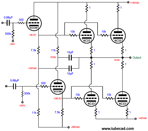
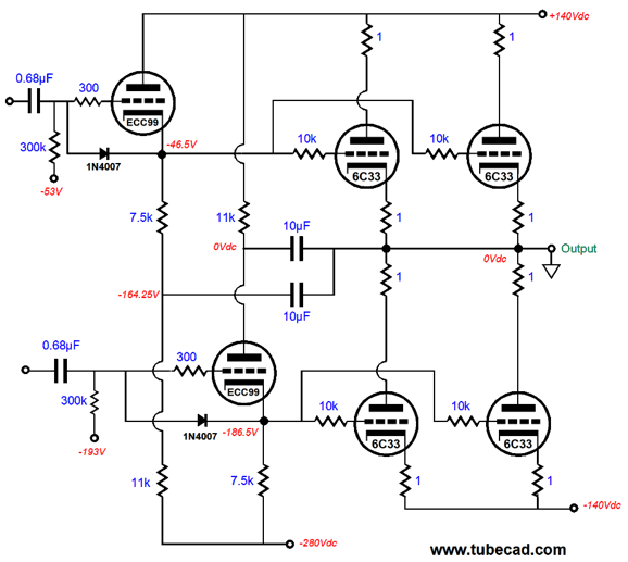
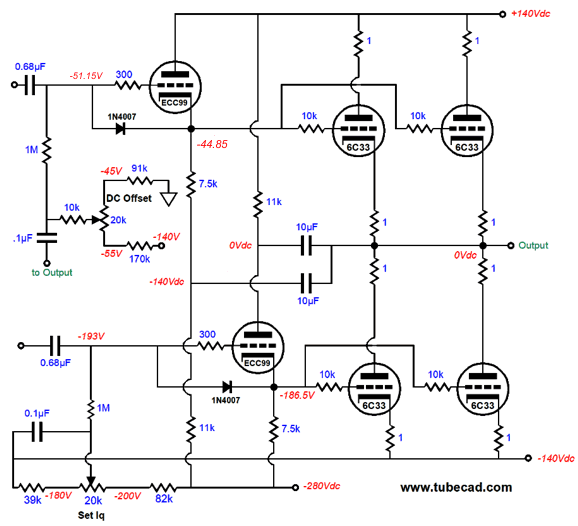
The solution is found in the two 10µF capacitors, which equalize both the cathode-to-plate voltage swings and current swings in the two cathode followers. How so? Let's get extreme. (This is my natural way of thinking. An unwillingness to think extremely betrays an unwillingness to think, as all thought requires exaggeration.) We assume at dead short to ground as the load impedance, i.e. zero ohms. (Note that I snuck in two protection diodes in the following schematic.)
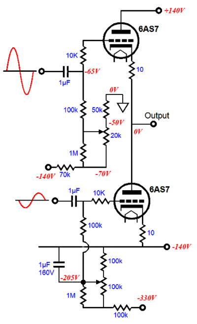
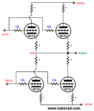
If the top cathode follower's grid sees a positive 40V upward swing, the bottom cathode follower's grid will see a negative 40V downward swing. This is the balanced condition for a zero-ohm load impedance in a totem-pole configuration. The top cathode follower responds by pulling up its cathode voltage by almost 40V, while the bottom cathode follower's cathode voltage falls by almost 40V. The top cathode follower effectively works into a 7.5k cathode resistor, as its 10µF capacitor terminates into the output stage's output, which is stuck at 0V; thus, effectively the 7.5k cathode resistor below it does not exist in AC terms. With the bottom cathode follower, its 10µF capacitor to the output prevents its plate voltage from moving. In this setup, both cathode followers work into 7.5k cathode load resistances; both see equal but anti-phase cathode-voltage swings and plate-current swings. Now, we imagine no external load, so the output stage can swing up and down without having to deliver any current external to the circuit. If the top cathode follower's grid sees positive 40V upward swing, its cathode might swing up 39V while the output stage's output swings up 38V, so the net change in grid-to-cathode voltage is +1V and the net change in voltage drop across the 7.5k cathode resistor is +1V. The top cathode follower cathode-to-plate voltage will decrease by 39V. What about the bottom cathode follower? Its grid will see a negative 2V downward swing, which the phase splitter will "knowingly" provide. The bottom cathode follower responds by dropping its cathode voltage by -1V and the net change in voltage drop across the 7.5k cathode resistor is -1V. The top cathode follower cathode-to-plate voltage will increase by 39V. In this setup, both cathode followers still work into 7.5k cathode load resistances; and both still see equal but anti-phase cathode-voltage swings and plate-current swings. If we remove the two 10µF capacitors, this equalized and balanced arrangement is off, as the top cathode follower will do far more work and experience far larger cathode-to-plate voltage and plate current swings. Moving back one more step, we encounter the phase splitter, which must attach to the output, as its job, beyond providing anti-phase signals, is to deliver dynamically equalized balanced signals to the top and bottom output tubes. Two key words in that last sentence were "dynamically" and "equalized." I have seen OTL totem-pole designs that acknowledged the need for asymmetrical drive signals for the top and bottom output tubes, but choose to implement a fixed ratio, one set for 8-ohm loads. The following design takes the ratios off the phase-splitter's plate resistors.
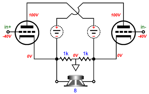
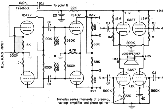
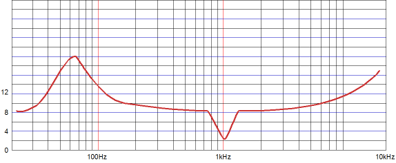
Note how the bottom triode get 50% of the signal that the top triodes get. A bad idea. Why? Almost no loudspeaker presents a fix impedance. Instead, we get the familiar roller-coaster impedance plot-lines.
What we need is a dynamically adjusting variation of the ratio that tracks the changing loudspeaker impedance. The phase-splitter's additional job is to equalize the two drive signals, as the top output tubes must see a much bigger drive signal, as their cathodes move up and down with the output signal—the only exception being the dead short to ground example.
A further requirement for the phase splitter is that it must be able to provide a drive signal for the bottom output tubes that contains 100% of the negative-power-supply-rail noise. If tit doesn't, if it provides a clean drive signal, then the negative rail ripple will be treated by a bottom output tubes as a signal to be amplified. About 99% of OTL designs make no provision for this last requirement. Why not? Negative feedback, gobs of it. OTL amplifiers run far higher negative feedback ratios then transformer-coupled tube amplifiers for two reasons: because they can, as a output transformer greatly limits the safe amount of negative feedback that can be applied; and because they must, as the output tubes are so poor a match for the low-impedance loudspeakers that the output tubes must be hammered into linearity. And one problem with high negative feedback designs is that its use allows for a lot of design slop. Since negative feedback is expected to clean up the mess, why bother trying create pristine power supplies or intrinsically low-distortion topologies? Much like having professional house cleaners arrive each day gives you license to make a mess, using gobs of negative feedback grants you the freedom to be sloppy. These three tasks the phase splitter must accomplish sound daunting, but the solution is simple enough.
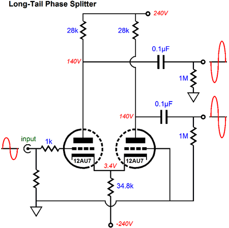
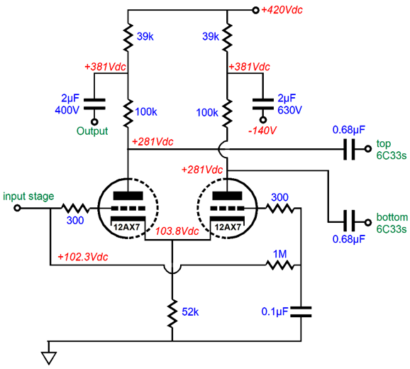
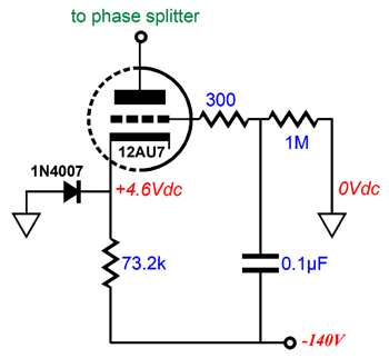
The two 2µF capacitors make all the difference. The capacitor on the left equalize the drive signals, in spite of impedance variations. The capacitor on the right purposely pollutes the bottom output tubes' drive signal with 100% of the negative-power-supply-rail noise. Both these tasks are made possible by the phase splitter's extremely high output impedance, which is ensured by either a large-valued common cathode resistor, in other words a long-tail resistor, or by replacing this resistor with a constant-current source. Speaking of which, the following schematic shows how to make constant-current source out of a triode.
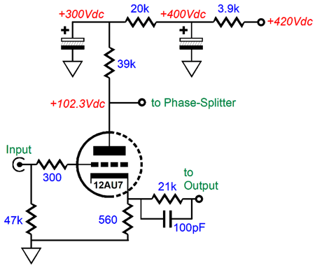
The 73.2k cathode resistor is magnified by the triode's amplifier factor (mu) plus one and to this product we must add the triode's plate resistance, i.e. Rk(mu + 1) + rp. A 12AU7 triode's mu is 17, so the effective plate impedance in this circuit becomes about 1.3M. This is plenty high, so we can put away are LEDs and cascoded high-voltage, depletion-mode MOSFETs. At last we arrive that the input stage. It has two jobs: to provide signal gain and to apply negative feedback to the entire amplifier. We could get extra fancy, but a simple grounded-cathode amplifier will work just fine.
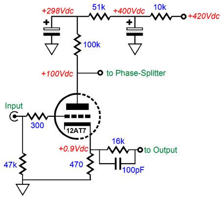
The triode's cathode is this amplifier's inverting input, while its grid is the amplifier's non-inverting input. The 12AU7's relatively low mu provokes a relatively low signal gain at its plate, so a better choice might be a 12AY7 or 12AT7 or 12BZ7 or 5751 or 5965. If octals are your preference, a 6SL7 would work, both as the input tube and in the phase splitter position. (The 6SU7 is a tightly matched version of the 6SL7, which was designed for use in differential amplifiers.) One danger, however, with using a higher-gain input tube is that establishing adequate phase margin will probably become more of an issue. Phase margin, what is phase margin? A power amplifier that uses a negative feedback loop runs into a problem at extremely high-frequencies in that the output signal's phase drifts away from zero and eventually becomes 180 degrees out of phase with the input signal. Not good, as the negative feedback has now become positive feedback and the amplifier is no longer an amplifier but a power oscillator. The key point of interest is what is amount of phase shift at the zero crossing point in the amplifier's falling gain—in other words, the amount of phase shift at unity-gain. If that amount of phase shift is less than about 145 degrees, the amplifier is not likely to break into oscillation; ideally, we strive to get not more than 90 degrees of shift. Many OpAmps are not unity-gain stable, as their phase shift is too great to allow that much negative feedback to be used; but can be made stable at unity gain by throwing away some of the negative feedback or by applying special compensation techniques (if the OpAmp's pins allow access to the circuit within). Okay, I just ran some SPICE simulation on this OTL amplifier with a 12AT7 input tube. Much better performance, as the distortion at full output (64W) fell below 0.1% and the phase margin was no worse.
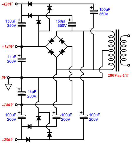
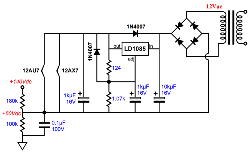
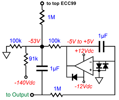
The Brazilian OTL power amplifier requires four power-supply rail voltages: +420Vdc, +140Vdc, -140Vdc, and -280Vdc. A nightmare of transformers and power-supply parts? No, not really, as we can get clever and let one center-tapped secondary create all four rail voltages.
Twelve rectifiers and eight capacitors are all it took. All four rails are full-wave bridge rectified, so 60Hz ripple or half-wave magnetizing of the power transformer core. The heater create their own set of headaches for us. The input tube and phase splitter tube should get a single regulated 12Vdc power supply, which will require a 12Vac winding and possibly its own transformer.
This heater power supply is DC referenced to+50Vdc by the two-resistor voltage divider. The top cathode follower and output tubes need their own floating 12Vac heater winding that is referenced to the output, so as the output swings up and down in voltage, so too does this winding. The bottom cathode follower and output tubes also need their own 12Vac winding, but this one must be voltage reference to the -140Vdc power-supply rail.
Each channel requires two ECC99 tubes, one for the top cathode follower and one for the bottom cathode follower. Only one of the two triodes will be used in each ECC99. What happens to the second triodes? We leave them floating, with the cathode and grid and plate tied together. The second triodes don't get hot, as their half of the heater element is not energized. This is not as wasteful as it might seem, as we could swap the bottom ECC99 with the top ECC99 and the unused triodes would be used. This would require that the top ECC99 tube socket only delivered AC voltage to pins 9 and 5, while the bottom socket only energized pins 9 and 4.
Since the 12Vac winding is too hot for the 6.3V half of an ECC99 heater element, we place two 8.2-ohm resistors in series with the element to drop the AC voltage down to 6Vac. These resistors will also greatly prolong the heater's life span, as they drastically limit the current inrush at startup. Setting the idle current and the DC offset requires two potentiometers.
Note how both potentiometers see a limited voltage range of 20V and how both are AC referenced through the two 0.1µF capacitors. This is essential with the high-valued plate resistors in the phase splitter. So, are we done? No, not really. Stop and think about it. We have a fine OTL design that addresses several important OTL issues that others want to ignore. But this amplifier is still a class-AB effort that is susceptible the same hidden problem that befouls all class-AB amplifiers, whether they be transistor- or MOSFET- or tube-based: gm doubling. While the top and bottom output tubes are all conducting, the output stage's transconductance is equal to twice what it will be once one set of tubes turn off, which means that the output impedance will double once one set of tubes cuts off. True, tubes tend to cut off in a much more gooey fashion than solid-state devices, but they do eventually turn off altogether; so while the slide into half gm may prove smoother, it still occurs. What is the solution? We need a constant-transconductance output stage. How do we do it? The easiest and cheapest solution is to add four afterburner transistors.
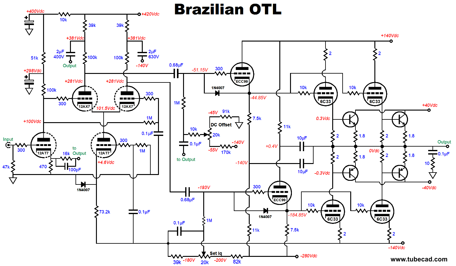
As long as the output stage is still operating within its class-A window of current flow, these transistors are shut off and not in the circuit. But as the bottom output tubes cutoff, the top two transistors turn on, providing the missing transconductance needed to restore a constant transconductance. Conversely, when the top output tubes shut off, the bottom two transistors turn on, helping the bottom output tubes achieve a constant transconductance. Really, John, what an icky solution. Well, we could add four extra output tubes at $60 each and buy a bigger power transformer to power their heaters and include some high-speed rectifiers to allow them to switch in when needed. Who knows, it just might work. But if the first watt is the most important watt, which I truly believe it is, then, by time the transistors kick in, we will be past that watt. (Just as the general practice of switching from premium alcoholic beverages to cheaper grade drinks once most the party goers are smashed makes sense, adding the transistors after the first watt makes sense.) In addition, the added transistors will increase the potential output power and extend the output tubes' life span. Couldn't we add power MOSFETs instead? We could, but their relatively high turn on voltage will add its own complications. I would give the added output transistors their own power transformer and rectifier circuit. In fact, if I was having custom power transformers made, I would have two made: one for the four power-supply rail voltages on the OTL circuit and one that would hold four windings for the heaters and the transistors. They would probably be the same size. Let's put it all together now, using a 12AT7 in place of the 12AU7.
Click on schematic to see enlargement Note that the schematic now includes a Zobel network at the output. Luis had wanted one, but I didn't think it would be necessary, but he was right, as SPICE simulations revealed. Luis also asked about a DC servo to auto eliminate the DC offset. Here is my solution.
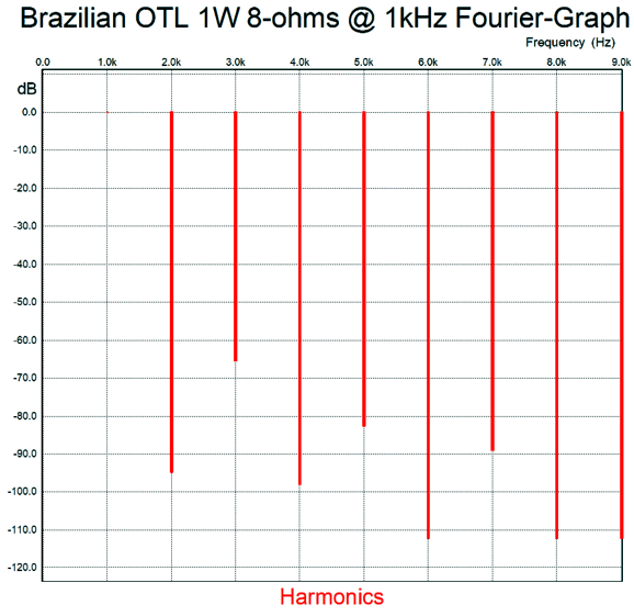
The secret is to strive to have the OpAmp's DC output centered at 0V at the target DC output voltage, which would allow it the widest range of operation. The added diodes are protection devices; I would use 1N4148 signal diodes. The complete schematic, including the many power supplies is available here as a PDF file. Now we are done. I actually had planned on presenting another OTL design, but my fingers are giving out (I am approaching 5,000 words), so it will have to wait for next time. But before signing off, here is the SPICE-produced Fourier graph for 1W of output at 1kHz into an 8-ohm load.
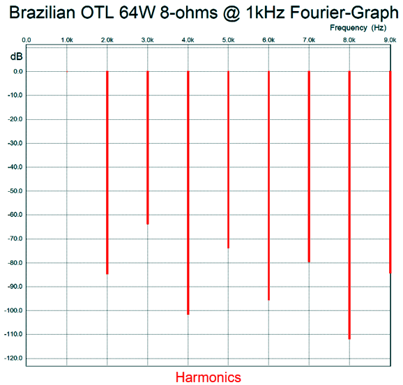
And then at 64w of output.
Not bad at all. Its harmonic signature is very push-pull and not single-ended, but then single-ended amplifiers do not put out 64W.
//JRB
User Guides for GlassWare Software
For those of you who still have old computers running Windows XP (32-bit) or any other Windows 32-bit OS, I have setup the download availability of my old old standards: Tube CAD, SE Amp CAD, and Audio Gadgets. The downloads are at the GlassWare-Yahoo store and the price is only $9.95 for each program. http://glass-ware.stores.yahoo.net/adsoffromgla.html So many have asked that I had to do it. WARNING: THESE THREE PROGRAMS WILL NOT RUN UNDER VISTA 64-Bit or WINDOWS 7 & 8 or any other 64-bit OS. I do plan on remaking all of these programs into 64-bit versions, but it will be a huge ordeal, as programming requires vast chunks of noise-free time, something very rare with children running about. Ideally, I would love to come out with versions that run on iPads and Android-OS tablets.
//JRB
|
|
John Gives
Special Thanks to the Special 69
I am truly stunned and appreciative of their support. In addition I want to thank
All of your support makes a big difference. I would love to arrive at the point where creating my posts was my top priority of the day, not something that I have to steal time from other obligations to do. The more support I get, the higher up these posts move up in deserving attention. Only those who have produced a technical white paper or written an article on electronics know just how much time and effort is required to produce one of my posts, as novel circuits must be created, SPICE simulations must be run, schematics must be drawn, and thousands of words must be written.
If you have been reading my posts, you know that my lifetime goal is reaching post number one thousand. I have 584 more to go. My second goal is to gather 1,000 patrons. I have 931 patrons to go. Help me get there.
Kit User Guide PDFs
Only $12.95 TCJ My-Stock DB
Version 2 Improvements *User definable Download for www.glass-ware.com |
||


| www.tubecad.com Copyright © 1999-2018 GlassWare All Rights Reserved |