| John Broskie's Guide to Tube Circuit Analysis & Design |
13 September 2010
Plate-Driven Phase Splitter And, who knows, maybe these circuits were gifts from God. How can anyone think of circuits in church? For me, it is quite easy, as I often get my most outside-the-box ideas in crowded, busy, loud rooms, such as coffee shops, restaurants and nightclubs (much like Boris Spassky, as I remember reading, who played his best chess games in raucous bars, a glass of vodka in hand, a wanton woman on his lap). The distractions seem to only distract the stodgy portion of my mind, allowing the untamed portion to run wild. Often the circuits derived from chaotic environments are too wild, too outside the box to be functional. And sometimes the circuits, as proved to be the case with one of my four designs, I have already designed, but forgotten. Of the three remaining circuits from Sunday, the first might prove workable, but I could not get it to run in SPICE, probably because it was too complex. Fortunately, I know a few workarounds, such as forcing initial conditions or splitting the circuit into subsections. The last two circuits, however, do pass the SPICE test and are quite interesting. Both use not the triode's grid, but its plate as a signal input. Although a triode's grid is the usual signal input port, all three of a triode's elements, its plate, grid, and cathode can function as a signal input. The grid offers many advantages: it presents a high input impedance, it can produce voltage gain when the output is taken at the plate (grounded-cathode amplifier) and current gain when the output is taken at the cathode (cathode follower). Feeding the input signal to the cathode can also result in voltage gain at the plate (grounded-grid amplifier), but its input impedance is low, seriously low, as Zin = (Ra + rp)/(mu + 1) || Rk.
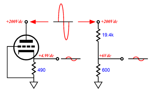
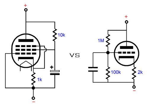
The plate, on the other hand, when used as the signal input, can never deliver any voltage gain at the grid or the cathode and its input impedance is fairly low, equaling the triode's rp (if the capacitor resistor is unbypassed, Zin = rp + [mu + 1]Rk). In fact, the plate is mu times less effective than the grid in controlling current conduction through the triode; for example, with a 6SN7, the grid is 20 times more effective than the plate. A triode's amplification factor (mu) is simply the measure of the relative effectiveness of the grid over the plate in influencing the flow of current from cathode to plate. So, why would we want to apply the input signal to the plate, rather than the grid? First, there are circuit configurations wherein voltage gain is not needed and where the cathode's low output impedance can be an asset. Here is an example, below are two high-voltage voltage dividers, the first consists of a triode and a cathode resistor; the second, two resistors. Both draw 10mA and both work as 1/35 AC voltage dividers. (The DC voltage division differs between the two.)
(Why does the 6SN7-based circuit yield only 1/35th and not 1/20th of the AC input signal, since its mu is 20? If the cathode resistor is replaced by a constant-current source, then the 1/20th voltage division would obtain, but the cathode's output impedance and the 490-ohm cathode resistor together define a secondary AC voltage divider.) Interestingly enough, these two voltage dividers differ in DC voltage division and in output impedance. The two-resistor voltage divider's output impedance is equal to the 19.4k resistor in parallel with the 600-ohm resistor, or 582 ohms; the tube-based voltage divider, the cathode's output impedance in parallel with the cathode resistor, or about 184 ohms. That's right, the tube-based circuit offers one third the output impedance. Stop right here and consider how strange this result is and then try to dream up electronic applications wherein this difference could be exploited. I did this over a decade ago when I needed to sample a high-voltage node in a single-ended amplifier and I had to keep the voltage divider's output impedance low, but without using low-ohmage resistors or extra complex circuitry or phase-shifting coupling capacitors. The plate-driven cathode follower was the answer.
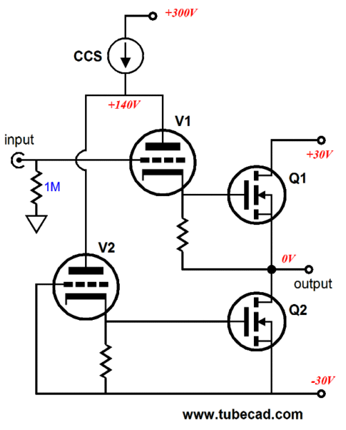
In fact, because the triode is not perfectly linear, it being easier to increase its current conduction than to decrease it, I was able to use this nonlinearity to my advantage, as it complemented the nonlinearity of the receiving tube down at ground level. The following circuit is the third that plopped into my mind last Sunday; it is a power buffer that offers unity gain and a low output impedance.
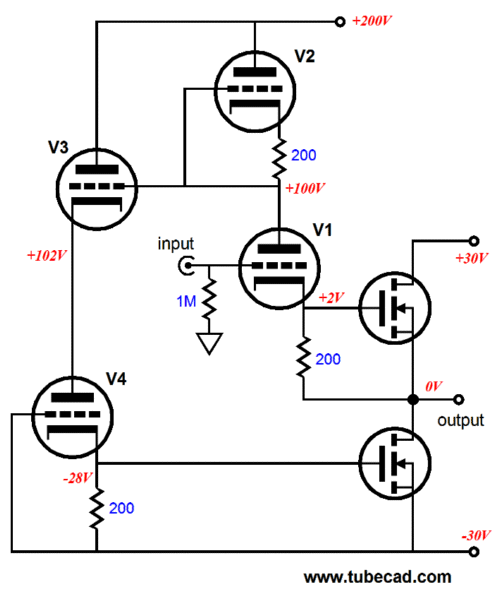
If it doesn't seem to make any sense to you , do not worry; it didn't make any sense to me either. Prior to designing this circuit, I had been wondering what a hybrid power amplifier, with MOSFET output stage, with an Aikido input stage would look like if I returned all the output signal to the Aikido input stage's bottom cathode resistor and then grounded the Aikido output cathode follower at the negative power supply rail. This circuit, however, is not exactly what I first imagined; it's far more interesting and if I had not been so distracted by the church proceedings, I would drawn my first concept down instead. My first response, after sketching this more interesting schematic out on the back of my service program, was to proclaim, "It will never work... or would it?" The more I stared at it the more I fell in love with it, although the more staid portion of my brain was not amused and demanded a mathematical proof before it would sanction the opening of any champagne bottles. The math was actually fairly easy, but a quick conceptual overview is faster. I started with my favorite extreme, a load impedance of zero, a dead short to ground at the output. With the output locked tight, a 1Vpk input signal will provoke a voltage gain of mu/2 from the input pair, V1 & V2, as V2 and its cathode resistor match V1 and its cathode resistor, which ends up splitting the triode's mu.
Triode V3 functions as cathode follower and its input so magnificently high that presents virtually no drag on the V1 and V2. Triode V4 functions as plate-driven cathode follower and its cathode-to-plate voltage swings will match those of V1, but with difference. When triode V1 see a positive input voltage, it increases in current conduction, thereby pulling down its plate, whereas V4 sees an unwavering grid voltage, so its response to its declining cathode-to-plate voltage is to lessen its current conduction. Now if all the triodes are of the same type and all use the same cathode resistor value, V4 will conduct perfectly in anti-phase with V1, so the voltage signal superimposed on V4's cathode resistor will match that superimposed on V1's capacitor resistor in amplitude, but in 180 degree phase shift. In other words, triodes V1 & V4 are in cathode-to-plate voltage phase, in anti-current phase to each other. "It is the harmony of the diverse parts, their symmetry, their happy balance; in a word it is all that introduces order, all that gives unity, that permits us to see clearly and to comprehend at once both the ensemble and the details." Symmetry is powerful and it is as close as we ever get to real magic. Here is a trivial example: if you were asked what the sum of all the integers between 1 and 10 was, you might start adding 1+2+3+4+5+6+7+8+9+10 in your head; you might even end up with the right answer, 55. On the other hand, if you saw the intrinsic symmetry of the integer rearranged into match pairs,
each of which adds up to 10, then problem would be much easier. Added together, these four matched pairs equal 40 and when added to 5, which did not find a symmetrical partner and 10, which didn't need a partner, yields 55 as the answer. Because with only had ten small numbers to be added together, the savings in thinking power is small. But if we convert this symmetry into a simple formula, sum = (X² + X)/2, then we can apply this formula to 1 to 100 integers and quickly get the answer 5050, as 100² = 10000, and 10000 + 100 equals 10100, and which divided by 2 equals 5050; or 1..1000, which equals 500500. Of course, many distrust fancy math stunts and prefer the solidity of grinding away instead. I won't list all the formulas required here, but the math is straightforward enough that anyone who cares can easily derive them on his own. This plodding approach, however, yields the same answer: balanced drive for top and bottom power MOSFETs. By the way, there is a great story about one of the greatest mathematical minds of the last century, Johnny Von Neumann. (I believe that Einstein said of Von Neumann that he was the most intelligent person he had ever met.) Von Neumann was once asked to solve the following math puzzle:
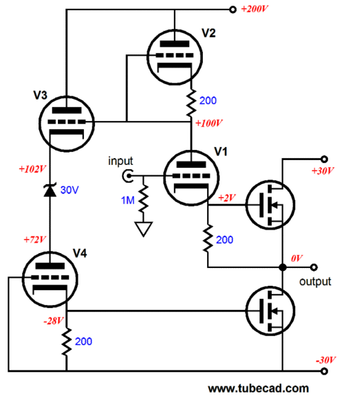
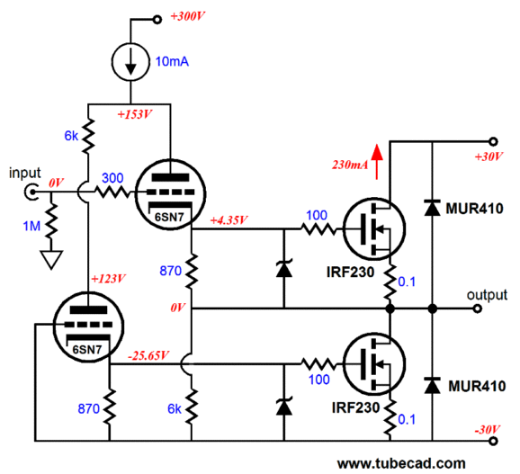
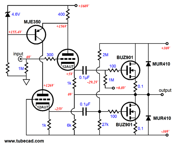
Von Neumann thought for a few seconds and came up with the right answer. Upon which, his examiner said, "Wow, that's amazing; most fall into the trap of trying to the solve the problem by a summation of an infinite series." Von Neumann replied, "But that's how I solved it." (The easy way to solve the problem is to realize that the trains will collide in one hour and since the bee travels at 20MPH, he will cover 20 miles before dying.) See thesciencepundit.blogspot.com for more information. Okay, back to the tube circuit at hand. No doubt some readers have spotted a problem with this circuit— namely, that while triodes V1 and V4 operate under the same AC plate voltage swings, they differ is DC operating points, as V1 sees a cathode-to-plate voltage of 98V, while V4 sees, 130V; and this imbalance will result in the bottom power MOSFET seeing too great a DC bias voltage. True. The workaround is to place a 30V battery or capacitor-bypassed resistor or 30V zener in series with triode V4's plate and V3's cathode. The last approach is shown below.
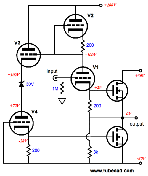
(Strictly speaking the zener voltage should have been 32V.) A secondary small problem is that all of V1's and V2's current must flow up from through the bottommost MOSFET, creating an imbalanced between MOSFETs. Adding an extra resistor gives the triodes an alternative current path to the negative power supply rail.
Of course, this circuit as shown in the schematic above is not loudspeaker ready, as it is missing many supporting parts, such as grid-stopper and gate-stopper resistors, fuses, and output protection circuitry. We do, however, get a good view of the topology, without the all the extra clutter.
Second Last Sunday Circuit
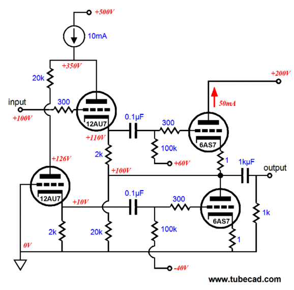
Once again, we start with a bare topology, shorn of supporting components. Triode V1 receives the input signal and its plate inverts and amplifies the signal until. How much amplification is realized? It depends on how well the MOSFET-based output stage follows it input signal. At one extreme, wherein the output is grounded, triode T1 develops a gain equal to mu/2, as V2 and its cathode resistor are V1's plate load. At the other extreme, wherein the output stage sees no external load, the output swings so closely to the input signal that V1 realizes very little gain, if any at all, maybe swinging only millivolts, which means that triode V2's cathode resistor will also see only millivolts of voltage swing. Once again, we have the issue of dissimilar DC operating points between tubes, so the following is a more fleshed out schematic.
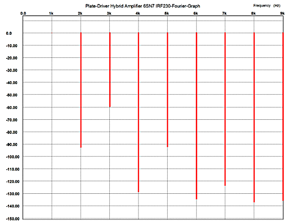
How well does this power buffer perform in SPICE? Very well indeed. Below is the Fourier graph for 1W (4Vpk) into 8 ohms @ 1kHz. As you can readily see, the harmonic signature is pure push-pull, with the even-order harmonics much more deeply suppressed than the odd-order harmonics. Is this a problem? It is if you love single-ended amplifier sound, but since circuit is a power buffer, which offers slightly less than unity gain, a large-swinging voltage driver stage will be needed. (My first choice would be a simple grounded-cathode amplifier, rich with 2nd and 4th order harmonics, which would help restore a more natural balance.) The buffer's output impedance is about 1.5 ohm; with a higher transconductance triode, such as the 6DJ8 or 5687, the output impedance will drop. By the way, the constant-current source (CCS) could be replaced with an inductor. Making a high-voltage CCS can take many forms. For example, depletion-mode MOSFETs or pentode usually come to mind. This brings up an issue worth considering, which of these two CCS provide the higher impedance?
Surely the pentode wins. Wrong. the pentode-based CCS presents about a 10k impedance, whereas the triode-based CCS (using a 6DJ8 as an example) presents an impedance of about 66k. Wy did the pentode lose? The screen resistor shunts the pentode. Now if the bottom of the pentode-based CCS were attached to ground and the 10k resistor attached to the B+ and the load attached to the pentodes plate, then the pentode-based CCS would indeed present a huge impedance. Returning to the topic of output impedance, imagine driving the buffer's output with an ultra-buffed, solid-state, power amplifier (or quickly attaching and un-attaching a battery's positive terminal to the buffer's output). Injecting a 1Vpk positive-going pulse into the output will provoke a much larger positive pulse at the topmost triode's plate, which will increase the bottommost triode's current conduction, thereby developing a positive pulse at the bottom MOSFET's gate, which will force an increased conduction on the bottom MOSFET, countering the applied pulse at the output, with each MOSFET equally bucking the pulse. So have we arrived? No. The key advantage of this topology is the DC coupling throughout; it is also it key disadvantage. What happens at start up, when the triodes are cold and not conducting or when a tube is jiggled (or pulled out of its socket) while the amplifier is on? What happens if the triodes are not matched or the MOSFETs are not matched?
A Safer Version
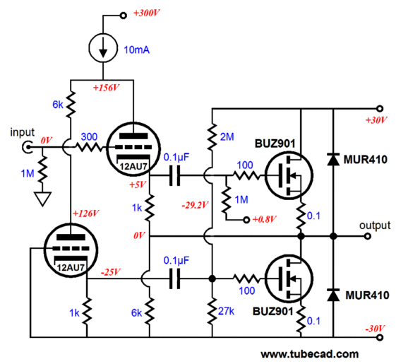
And with the coupling capacitors, a DC servo loop can be added to keep the output's DC offset low. In addition, if one of the 30V power supply rail fuses blow, the loudspeaker is still safe as the output will not slam into one rail, whereas without the coupling capacitors, such a calamity would be likely; for example, imagine the +30V fuse blowing, preventing the top MOSFET from pulling up, allowing the bottom MOSFET to pull down, as its gate would still see its DC bias voltage; in the safe example above, if the +30V fuse blow, the bottom MOSFET loses its DC bias voltage and it turns off. Before leaving this topology, I will show you an interesting variation, which forgoes the constant-current source and uses a PNP high-voltage transistor to ensure balanced drive. The main advantage this variation holds over the previous one is that since the top triode's plate is locked at 156Vdc, a much lower high voltage power supply can be used. (In the previous circuit, the plate will undergo some huge voltage swings at full output.) This new variation works differently from the previous. Here the transistor strives to see a constant voltage drop across the 400-ohm resistor that connects to the HV B+, which means that the resistor must experience a constant-current draw through it. But the topmost triode's current will vary with the input signal, so the bottommost triode's current must be made to vary in anti-phase, so the sum will remain constant.
Since the bottommost triode's grid is locked at the negative power supply rail, the only way its current conduction can be made to vary is by varying its plate voltage, which the transistor is happy to do. The disadvantage that this variation suffers from is that the high voltage power supply should be regulated, whereas in the previous version, it didn't need to be, as the constant-current source shielded the tubes from any ripple.
Tubes at Last
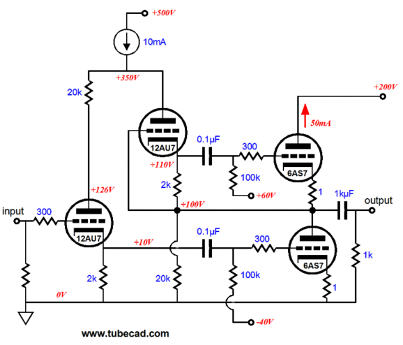
Such a power buffer would be useful for driving low-impedance headphones. To create a big OTL power amplifier would require many more output tubes and a slightly reconfigured plate-driven phase splitter stage, as the 6AS7 tubes require huge voltage swings at their grids to achieve full output into 8-ohm loads. Even with the wimpy 32-ohm load, this buffer suffers from a -20dB insertion loss; in other words, 10V input signal will yield 1V into 32 ohms. Thus, a super high-gain input stage will need to be added to this OTL. And such an addition may still not be enough, as the triodes must see bigger than huge plate voltage swings to make a go at power OTL amplifier, which would require a bigger than huge high voltage power supply to feed the constant-current source. Alas, as configured, this OTL must remain an interesting headphone amplifier design, not an OLT power amplifier. The sneaky, lawyer-like phrase in the last sentence was "as configured." If we alter the configuration, we alter the functioning. For example, what happens if we drive the bottom triode instead of the top triode? The buffer becomes an amplifier and the input signal phase is inverted at the output. In addition, the output impedance skyrockets. But the fundamental principle behind the phase splitting operation remains the same.
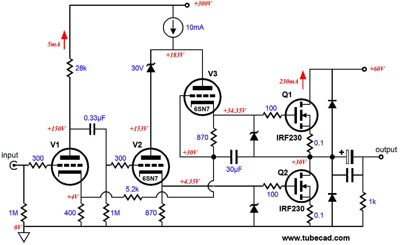
Rather than flesh out this revised OTL amplifier, below is a the same topological twist applied to the hybrid buffer, transforming it into a power amplifier.
What happened to the internal coupling capacitors, whose inclusion were deemed so critical before? The coupling capacitor at the output makes me much less worried about damaging the loudspeaker, but the coupling capacitor could—and maybe should—be reintroduced. Since both sides of the 30µF capacitor are at 30Vdc, why is this capacitor in the circuit? In actual use, the two sides of the capacitor are not likely to be at the exact same DC voltage, which will cause a huge imbalance in current conduction between the two power MOSFETs, as these device offer a screaming high transconductance, which will greatly magnify the voltage differential, throwing the output to the B+ or to ground. This capacitor prevents such a rail slam. The input triode V1 is also a 6SN7 type, although not marked as such. This triode both provides extra voltage gain and a ready feedback port at its cathode. Note how the 6K current-path resistor in previous examples has mutated into a feedback loop resistor pair. Because the input stage inverts the signal phase, the output is now in phase with the input signal. How well does this hybrid power amplifier perform in SPICE?
With the same 1W into 8-ohm load at 1kHz, the distortion about 0.1%. The output impedance is about 1.2 ohms. The 6SN7 is probably not the best choice, as a 12AX7-5687 combination would probably yield much higher performance, but three 6SN7s, bracketed by large black heatsinks, would certainly look cool.
Next Time
//JRB |
|
Kit User Guide PDFs
E-mail from GlassWare customers:
And
High-quality, double-sided, extra thick, 2-oz traces, plated-through holes, dual sets of resistor pads and pads for two coupling capacitors. Stereo and mono, octal and 9-pin printed circuit boards available.  Aikido PCBs for as little as $20.40 http://glass-ware.stores.yahoo.net/ Only $19.95
Download or CD ROM www.glass-ware.com |
||


| www.tubecad.com Copyright © 1999-2010 GlassWare All Rights Reserved |