| John Broskie's Guide to Tube Circuit Analysis & Design |
29 April 2005 
April and Eliot How I envy those who can load their car with all their belongings and move as easily as Paris Hilton changes boyfriends. After packing and unloading hundreds of CDs, magazines, electronic parts, tubes, and books, lots of books, I wish I had been brought up a Buddhist. Well, that's at least up to and during the move and while unpacking, but once settled, I cannot imagine not having a good-sized library. Yet, many—maybe most—are happy to own no more than a few books: a few coffee-table books filled with glossy pictures, a few self-help titles and cookbooks, a sci-fi novel that was never finished, the Ann Rice novel that was read twice, well, at least the good bits were read twice. Upon entering a nearly book-free house, I feel like the doctor who performs an autopsy on a body and discovers that it is missing a brain; and we both ask ourselves the same question: How could anyone live that way? Yet, I know many intelligent folks that don’t own more than a handful of books. If you are thinking that web access eliminates the need for books, this excuse cannot cover that much, as these folks didn't own any books prior to easy web navigation. In fact, I understand that the percentage of heavy readers has fallen to an all time low, yet more books are sold today than ever. How are those two outcomes compatible? Something like this occurs with audiophiles. Too many times I have seen $20,000 stereos systems supporting only twenty albums, shoddy albums at that: mostly test records, a few greatest hits collections, and several of the audiophile sanctioned group of pop albums played at stereo shows and audio salon showrooms. On the other hand, I have know committed music lovers that own thousands of records, tapes, CDs, and have spent no more than a few hundred dollars on their stereo. One college friend owned over 800 Beethoven record albums, which held at least a dozen different renditions of Beethoven’s 5th symphony; when he was tested by playing a small excerpt from one of the recordings, he would always guess the right conductor. Glenn Howard owns over a quarter million albums and I have never been able to stump him on an obscure LP; he just rattles off the list of songs on albums so rare that I thought that he might not own a copy. Glenn is not an audiophile. He doesn't worry about his power cords being broken in or his cartridge not being the current absolute. He just loves music. Thus, I have come up with Broskie’s Rule: your audio system should never cost more than your music collection. Class-AB auto-bias circuits At the complex end, we could build a circuit that only sampled the bias current when no signal was present or a circuit that ignored error signals beyond the class-A mode of operation. The first approach would work best with a small microprocessor-based circuit that would monitor the current at startup, while the input was shorted to ground, and then would lock the bias via digital potentiometer until the amplifier was turned off. Of course, some amplifiers never are turned on and remain on for months and idle current can drift over a relatively short amount of time. The alternative technique—throwing away error correction signals that occur beyond class-A operation—is much simpler to implement, as it only requires a few extra diodes. 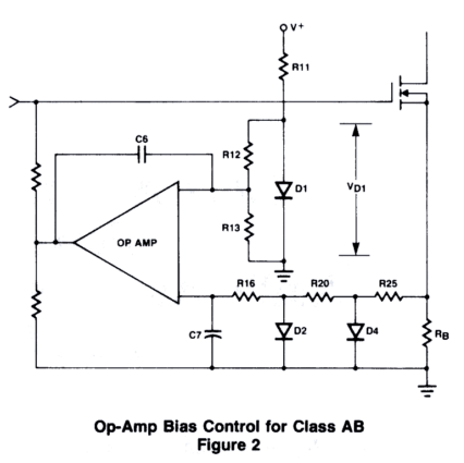
The above circuit appeared in Siliconix’s MOSPOWER Applications Handbook, 1984, p. 6-106; and originally appeared in a paper in the June 1982 IREE (ICCE). If the circuit does not make any sense to you, you are not alone. The first time I saw the circuit, I felt that it was time to tear up my big-brain club card, as I could not see how this circuit could work. If the top input on the OpAmp is the inverting input, then the OpAmp amplifies positive-going errors in bias positively! Watch out; amplifier on fire! If the top input on the OpAmp is the non-inverting, then the OpAmp applies positive feedback to the non-inverting input, which must also spell D-A-N-G-E-R. The circuit that should have appeared is shown below. The transistor at the OpAmp’s output inverts the OpAmp’s output, making the whole circuit work, as the OpAmp’s non-inverting input effective becomes the servo’s inverting input. 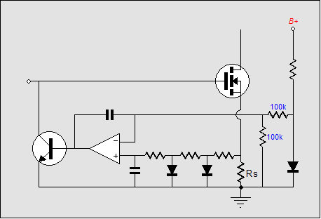
How does it work altogether? Since class-A operation ends when the output stage current exceeds twice the idle current, we need a reference voltage that bisect the clipping voltage produced by the shunting diodes. Thus, the voltage reference is derived from halving the voltage drop across the diode at the extreme right. The two 100k resistors define a 50% voltage divider that yields exactly half of the clipping voltage as the reference voltage. The diode's voltage drop defines the clipping voltage. Therefore, as long as the amplifier is run in class-A, the shunting diodes never become forward biased and, thus, never conduct, effectively falling out of the circuit. Under these conditions, in other words, under class-A operation, the DC servo strives to maintain an average idle current equal to the reference voltage divided by resistor Rs. 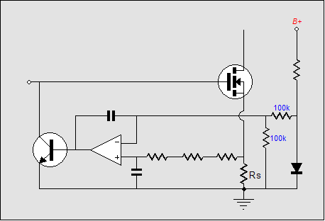
When the amplifier is called upon to produce more than a small fraction of a watt (when it falls out of class-A), the shunting diodes become forward biased and conduct, clipping the maximum voltage that can be presented to the OpAmp’s non-inverting input. Since the clipping voltage is twice the reference voltage, won’t the capacitor at the OpAmp’s non-inverting input become charged to that value?
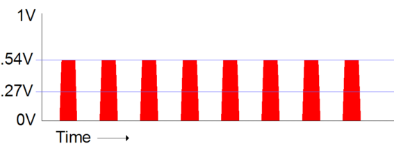
No, it cannot; as the input signal presented to it looks like a square wave with a peak magnitude equal to twice the reference voltage, as shown below, which averages outs to close to the voltage reference.
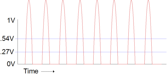
Interestingly enough, this circuit works best when the amplifier is putting out almost all of its potential power, as at lower signal levels the square wave looks more like half-wave rectified sine waves, as shown below. 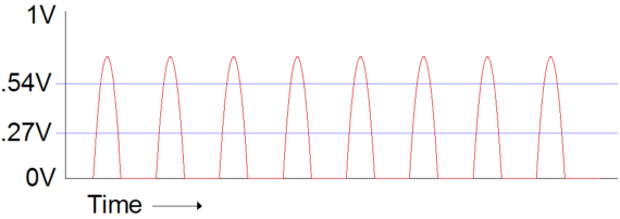
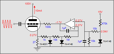
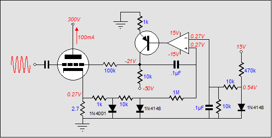
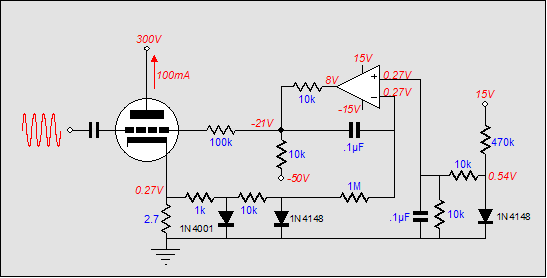
So, how well does this circuit work? Not that bad, after some tweaking. The bias voltage does drift during prolonged signal bursts, but with careful selection of the resistors feeding the shunting diodes, the rate of drift can be reduced substantially. Enough already with MOSFETs! What about tubes? The same circuit can easily be used with triodes, tetrodes, pentodes, FETs, IGBTs, and transistors—after suitable bias arrangements have been made, such as a negative bias voltage for the tubes and FETs. The circuit below works quite well and only uses one OpAmp.
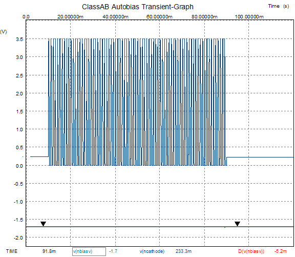
Not perfect, but definitely usable. Below is a SPICE simulation of the above circuit, with a 6DJ8.
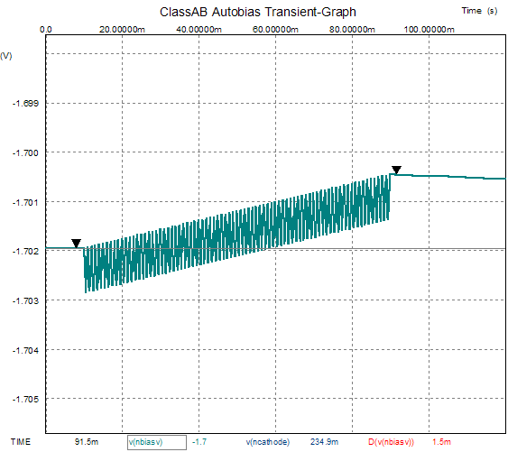
10Vpk, 1kHz tone burst Not too bad: the bias voltage drifted by only 5.2mV after the 10Vpk, 1kHz tone burst. A 2Vpk tone burst throws the bias voltage off by 1.5mV. Of course, the longer the burst, the greater the bias error.
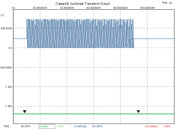
2Vpk, 1kHz tone burst
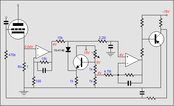
2Vpk, 1kHz tone burst As shown, the circuit can only provide a negative bias voltage down to the OpAmp's negative rail voltage (well, close to it). Two workarounds present themselves: add a PNP transistor or add an extra resistor to the output.
In both cases, an extra negative power supply will be needed. Note the 2.7-ohm resistor at the cathode and the 300V plate voltage; these examples are no longer using a 6DJ8. Morgan Jones' class-AB auto-bias circuit
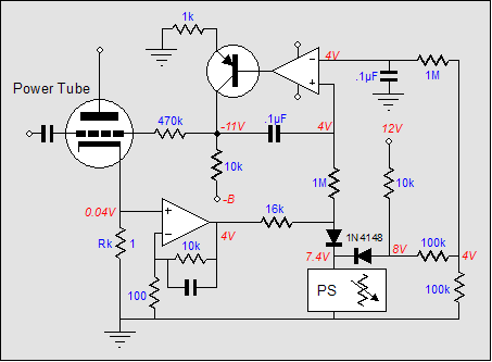
(By the way, I have been meaning to review Jones' Valve Amplifiers, 3rd Edition, for some time now, but I haven't finished reading it yet. I will, however, let the 6SN7 out of the box and urge you to buy it, even if you already own the previous edition. His book makes an excellent overview of not only tube electronics, but audio electronics in general, with good, solid information on capacitors, resistors, power supplies, and plenty more. And I mean plenty more; he covers many small topics that will inform the most experienced tube fancier. If you like this journal, you are going to like his book. Buy it.) I would do his circuit a bit differently, of course, as I even do my own circuits differently the next time I build them. As shown below, I would include the PNP grounded-emmiter amplifier in the OpAmp's AC feedback loop, which would simplify the design slightly and improve stability.
The future: a non-clipping auto-bias circuit //JRB |
Support the Tube CAD Journal TCJ Push-Pull Calculator
TCJ PPC Version 2 Improvements Rebuilt simulation engine *User definable
Download or CD ROM For more information, please visit our Web site :
|
|||


| www.tubecad.com Copyright © 1999-2005 GlassWare All Rights Reserved |