| John Broskie's Guide to Tube Circuit Analysis & Design |
10 March 2005 Which Tube Shall I Use ? "Which Tube Should I Use?" Typos My guess is that few tried pursuing the math to its conclusion; it did look daunting. The article’s punch line was that an unbypassed cathode resistor arches a triode’s transconductance curve upwards, as it lowers its slope. If the triode were perfectly linear, the resistor would only add distortion, but as the triode isn’t perfectly linear (because it already bends in the opposite direction), the unbypassed cathode resistor helps to straighten the curve by reducing the 2nd harmonic while increasing the 3rd harmonic. A key point is that too large a value will over compensate the triode. Thus, some finesse is needed. (Another example of "more, more, more" not working, not working, not working.) I recommend using a potentiometer and triangle waves to dynamically find the optimal amount of unbypassed cathode resistance needed. The circuit below shows one possible setup. 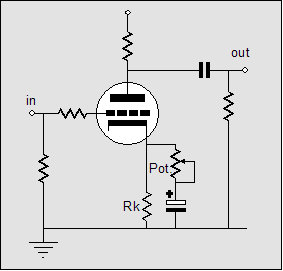
Resistor Rk sees all of the DC idle current through the triode, whereas the potentiometer and capacitor only see any current flow when AC signal is present. The capacitor is always charged to the cathode’s DC value, so the bias point will not be thrown off by adjusting the potentiometer. At one extreme of the potentiometer, the cathode resistor Rk is completely bypassed; at the other extreme, relatively unbypassed (if it were completely bypassed, the capacitor would have to pass DC current). In AC terms, the potentiometer’s un-shorted resistance is in parallel with resistor Rk. (A good starting value for the potentiometer is whatever you have in your part bins that is closest to resistor Rk's value.) By using triangle waves instead of sine waves, we can readily see changes in linearity, as our eyes can easily see a tad of distortion in a straight line, whereas it is difficult to see a gob of distortion in a sine wave. Once an optimal amount of cathode resistance is found, we can move on to the circuit below. 
We have added an unbypassed cathode resistor in series with a bypassed cathode resistor. (I have gotten e-mail from readers jazzed by a bold new grounded cathode amplifier circuit that uses two unbypassed cathode resistors in series. Well, here is chance to actually do something worthwhile with the extra cathode resistor.) Let’s say that in test setup we found that optimal potentiometer position presented a resistance of 330 ohms and that the unbypassed cathode resistor was 500 ohms in value. Now, 330 in parallel with 500 equals 200, so we have our resistor values: the bypassed resistor equals 500 – 200 ohms (300 ohms) and the unbypassed resistor equals 200 ohms. The bypassed cathode resistor can be replaced by a constant-current source FET diode or the LM134 (LM234, LM334) IC (I = 67.7mV/Rset) or a zener or a rechargeable battery. In the case of the battery, the large-valued bypass capacitor can be replaced by a small-valued, high-quality film capacitor. 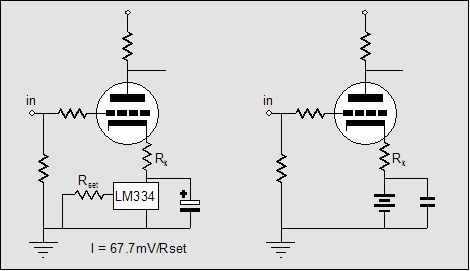 Constant-current draw amplifier 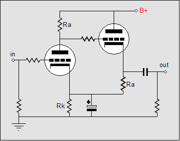
This circuit was the result of my attempt to find a perfect bypass capacitor blend. I started with a grounded-cathode amplifier with a bypassed cathode resistor and fed the grid a 10kHz square wave and attached a scope probe to the cathode. The electrolytic capacitor alone failed to shunt an amazing amount of high-frequency signal. Adding film and ceramic capacitors helped, but far too much signal could be seen on the cathode. I then replaced the cathode resistor with an LED, diodes, zeners, and IC voltage references. No part was perfect, as each still embodied some resistance or reactance, which against the alternating current produced a signal at that cathode to be amplified as much as if it had been applied to the grid. The solution? What if the current didn’t alternate? The cathode follower works in anti current phase to the grounded-cathode amplifier, so the current flowing from both branches add up to a constant current through the common cathode bias element. (Ideally, the cathode follower loss of gain must be factored into the mix, but making the cathode follower load resistor equal to the grounded-cathode amplifier’s plate resistor works close enough for most applications. Below is the modified constant-current draw amplifier. Both the grounded-cathode amplifier and the cathode follower benefit from a small amount of unbypassed cathode resistance. 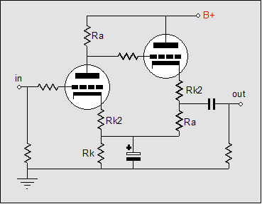
The cheat //JRB |
Support the Tube CAD Journal & get an extremely powerful tube-amplifier simulator for TCJ Push-Pull Calculator
TCJ PPC Version 2 Improvements Rebuilt simulation engine *User definable
Download or CD ROM For more information, please
visit our Web site : To purchase, please visit our Yahoo Store:
|
|||


| www.tubecad.com Copyright © 1999-2005 GlassWare All Rights Reserved |