| John Broskie's Guide to Tube Circuit Analysis & Design |
|
14 September 2020 Post 513
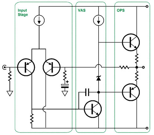
More Tube Output Stages In contrast, solid-state tends to follow either the same classic three-stage design of a differential input stage followed by a VAS intermediate gain stage and ending in an emitter follower output stage or are class-D designs that very few have any interest in understanding.
True there are some exceptions, such as solid-state circlotrons and class-G and class-H efforts, but such infrequent deviations are exceptionally rare. The same classic three-stage design doggedly and depressingly dominates. In truth, the most interesting thing about most solid-state amplifiers is their casework. Thus, we see fancy heatsinks and much machine-shop wizardry. (In my group of fellow amplifier designers, we have a running joke about who can come up with the most extreme selfless amplifier topology. Here "selfless" refers to a solid-state amplifier topology that is so bewilderingly out there as to exclude entirely its possible inclusion in any book or article by Douglass Self and to be inconceivable, if not incomprehensible, to any self-respecting solid-state amplifier designer.)
On the other hand, tube are in themselves interesting to behold; glowing and glass encased, burning hot and intricately assembled, tubes catch our eyes. I remember the owner of a stereo store telling me that he always saw a huge increase in window shoppers when he put a tube amplifier in his display window. He went on to say that, oddly enough, young couples on dates seemed most attracted to the vacuum tube gear. I also remember how mainstream audio magazines, even those magazines whose editors were staunchly opposed to tubes, repeatedly graced their magazine covers with images of shiny tube amplifiers. In other words, even if a perfect solid-state amplifier appeared tomorrow, which undoubtedly would be an IC, we can expect that tube amplifiers will still sing and continue to glow 100 years from now.
In my last post, we saw several simple tube-based push-pull output stages that held their own negative feedback loop. The idea was that we could build a power amplifier out of two amplifiers in cascade, each with its own negative feedback loop, but no global loop. Adopting this approach grants us increased flexibility and stability, but at the cost of not achieving the lowest possible static THD. By "static," I mean using a sinewave generator and an 8-ohm load resistor. In contrast, I am convinced that a two-amplifier cascade could yield lower dynamic distortion. By "dynamic," I mean actually playing music.
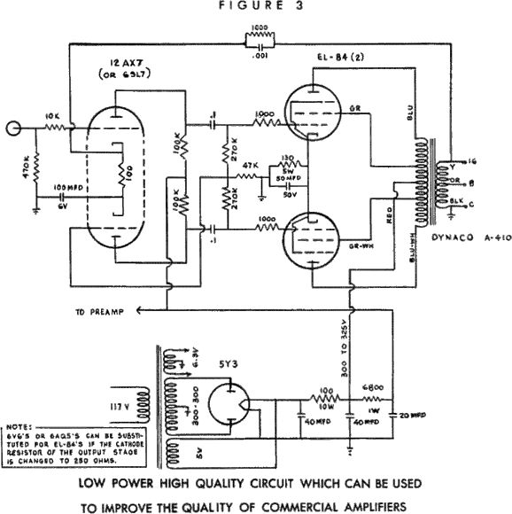
Dynaco Low-Power Design
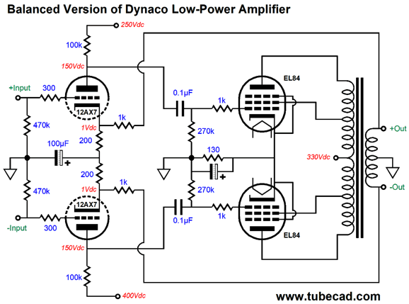
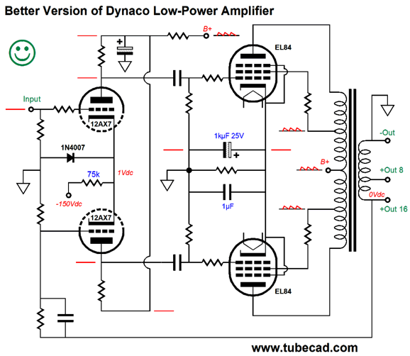
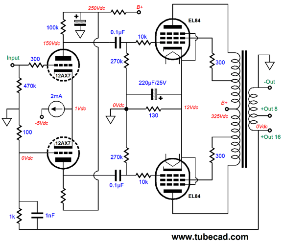
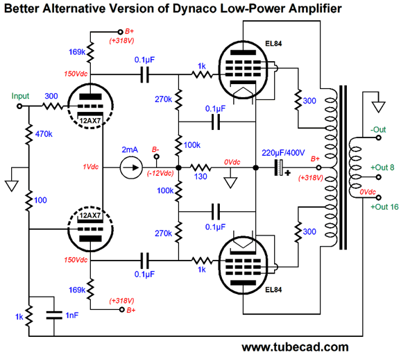
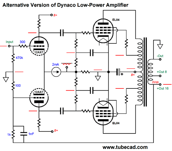
I assume that at the time of this design's creation, Dynaco didn't sell amplifiers based on the EL84 output tube, but they did sell output transformers for the EL84, the A-410, which was a potted design. A similar Dynaco output transformer, but not potted, for use with EL84 tubes was the Z-565. This little output transformer is my favorite from Dynaco—and I own several of the potted Dynaco A-430 and A-431 60W output transformers. Drive the Z-565's primary with a squarewave generator and you get a rounded squarewave on the secondary, not something that looks like a jagged mountainscape. (I have long dreamed of building a 60W stereo power amplifier that held four Z-565 output transformers and four EL34 output tubes per channel, with the output tubes mounted horizontally and protruding at both sides, making for a low-profile chassis but a big sound. It would resemble a flat-eight-cylinder car engine.) Okay, back to the Dynaco circuit, note that the negative feedback resistor also serves as the shared cathode resistor for both 12AX7 triodes. Also note how the capacitor shunts the AC signal at the bottom 12AX7's cathode to ground. Dang clever and cheap. Well, converting this design to accept a balanced input signal is easy enough.
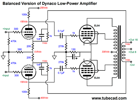
Two negative feedback loops are used, both of which serve as cathode resistors, as they provide a path down to ground through the center-tapped secondary. Unfortunately, the Z-565 doesn't hold a center-tap. (The Dynaco ST-70's output transformer, the A-470, does offer a secondary center-tap.) The workaround is the following.
The shared 390-ohm cathode resistor effectively sees a DC current flow. If we wish, we can shunt this shared resistor with a large-valued capacitor.
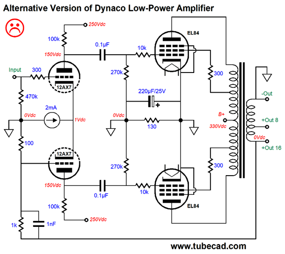
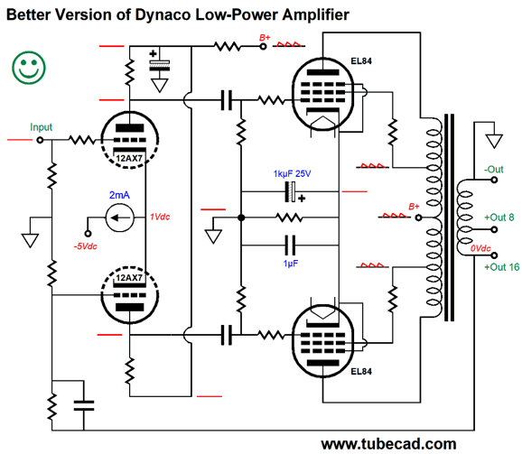
Unbalanced Dynaco Low-Power Design
Unfortunately, we instantly run into a snag: the 12AX7 cathodes sit at only 1V above ground potential, not enough to use a solid-state constant-current source, such as the LM334, which will need at least 3V to work best.
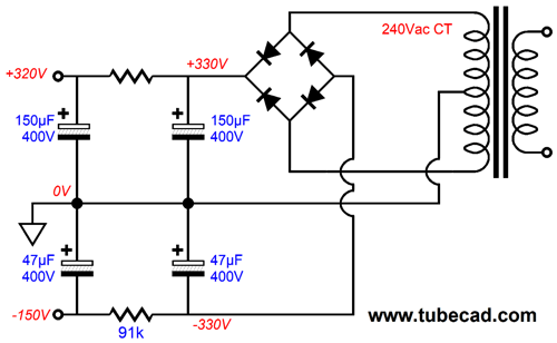
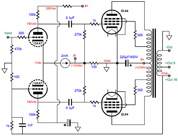
One workaround would be to add a negative power-supply rail voltage, which is easy to do when the power transformer offers a tap for creating a negative bias voltage.
The 91k resistor and the 47µF do a good job of filtering the -150V rail.
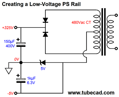
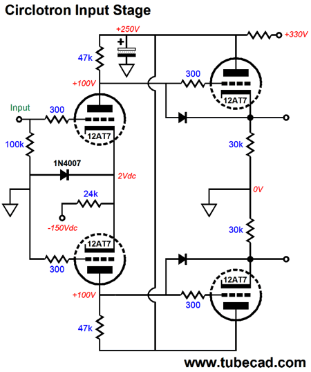
Well, an alternative sneaky workaround is to use the existing mono-polar power supply and shift the ground to a slightly higher voltage within the circuit. Is that possible? Indeed it is. The following trick is little known, but a godsend when needed.
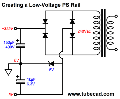
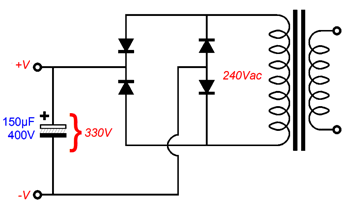
The center-tap no longer terminated directly into ground; instead, we place zener between ground and the center-tap. The result is that the center-tap now sits at -5V. (If a 12V zener were used, it would sit at -12V.) I have used three 1N4001 rectifiers in series in place of the zener, as the resulting 2.1V voltage drop across the diodes, added to the cathode voltage of the input stage, was enough to run an LM334 constant-current source. Note that the -5V came, however, at the expense of losing 5 volts of B+ voltage. We can pull off the same trick with a full-wave-bridge rectifier arrangement and no center tap.
Either of these power supplies can power the following design.
Okay, we have taken care of the constant-current source's voltage needs. Now let's look at the PSRR issues.
Things look good, as the only the EL84 plates and grid-2 see the raw B+ noise, but the output is noise free, as the the noise is common-mode signal that the output transformer ignores—at idle that is. When one El84 cuts off, the balance in noise is broken, and the noise becomes signal to passed to the secondary. I am convinced that this explains why a push-pull tube amplifier can sound just magical at low power levels, but suddenly coarsen as the volume increases. Here is a workaround, which forgoes the need to create a negative power-supply rail voltage.
The signal ground now is located at the output tubes' tied cathodes. The shared cathode resistor now does double duty, as it serves as both a cathode-bias resistor and as an RC resistor that filters the power-supply ripple. The power supply must be floating, i.e. not grounded, but it can be shared with to channels. DO NOT, however, use a single cathode resistor for both channels, as Dynaco did in both their T-35 and SCA-35 models.
Since the shared output cathode resistor sees a voltage drop of about 12V, the constant-current source now has enough voltage headroom to operate. The next move is subtle. Since the output tube cathodes are tightly coupled to the B+ voltage through the RC capacitor, we can forgo the filtering of the B+ voltage for the input stage, which allows us to use larger-valued plate resistors on the input stage, making for more gain and, thus, more negative feedback.
Note the added 100k resistors and 0.1µF capacitors; both work to improve the PSRR.
You can see that the power-supply noise is located below the output stage's cathode resistor. If we really want to isolate it, we could replace the shared output tubes cathode resistor with a constant-current source, but this would limit us to class-A operation of the output stage. For many, however, the idea of not grounding the power transformer's secondary center-tap is unthinkable, but they do like the idea of the constant-current source and the higher plate resistor values, so something will have to give.
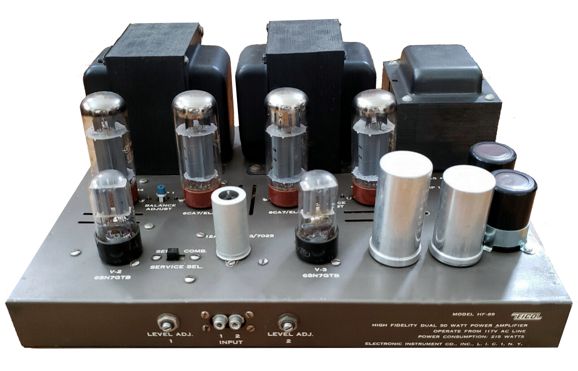
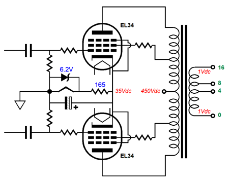
Balancing the Eico HF87
This arrangement worked due to the each EL34 drawing 75mA of current, so the two combined to 150mA, which the heater needed. The roughly part comes into play due to the heater element making a poor resistor. Resistors are amazing devices, as most resistances vary with the applied current flow, but not resistors, which are astoundingly immune to changes in temperature and current flow and voltage drop. Fortunately, when the HF87 was driven to full output, the output stage current draw increase to only 157mA. The modern workaround would be to place a 6.2V zener across the heater element; and in the other channel, place a 165-ohm resistor in series with a 6.2V zener.
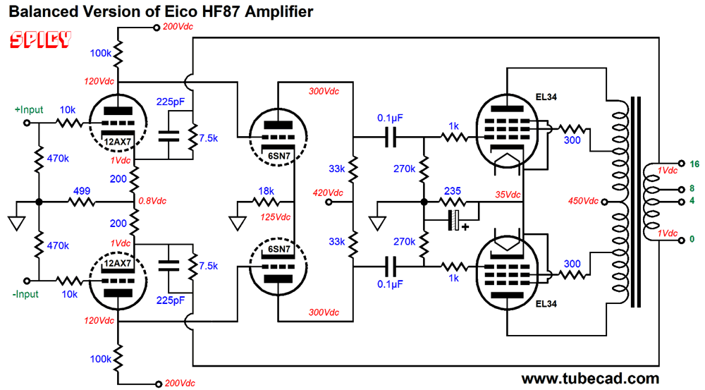
If the phase splitter held a 12AU7 instead of the 6SN7, the same trick could be used to get free DC heater voltage. Okay, how do convert this design to accept a balanced input signal? The first step would be to use the other 12AX7 triode. The next step would be to reduce the amount of negative feedback.
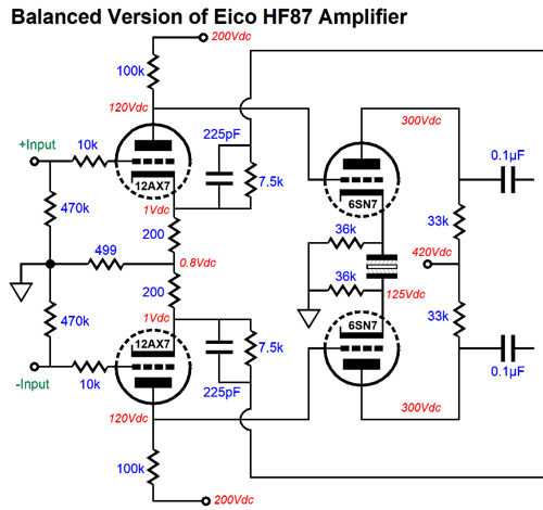
The design earns the SPICY label due to this circuit working perfectly in SPICE, but possibly running into trouble in reality. Why? The DC coupling between the input stage and the phase splitter assumes that the 12AX7 triodes are perfectly matched within their glass envelopes. In SPICE, all 12AX7s are perfectly matched; reality differs. One workaround would be to add a balancing potentiometer, but I hate potentiometers and the need to make adjustments. My workaround would be to give each 6SN7 triode its own cathode resistor and then bridge the two cathodes with a large-valued non-polarized electrolytic capacitor, say a 47µF / 50V capacitor. This way, the 12AX7 plates could differ by 10V and the phase splitter would still work well.
Another possible workaround would be to add input coupling capacitors at the front of the circuit and add a DC servo, which would ensure that each 12AX7 triode draws the same DC current at idle. If a two-amplifier-cascade were the goal, the first amplifier would be a phase splitter with a fixed gain, which would have to end with two output coupling capacitors anyway, so we wouldn't need to add coupling capacitors. The DC servo would simply read the DC voltage at one 12AX7 cathode and vary the other 12AX7's grid voltage to establish the same cathode voltage. Assuming 1% cathode and plate resistors, the plate voltage would have to be with 2% of each other. If we were truly bold, we would sample the DC voltages at the 12AX7 plates.
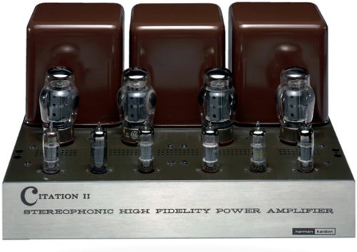
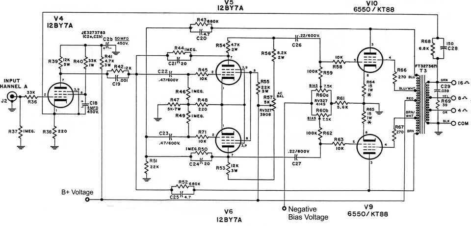
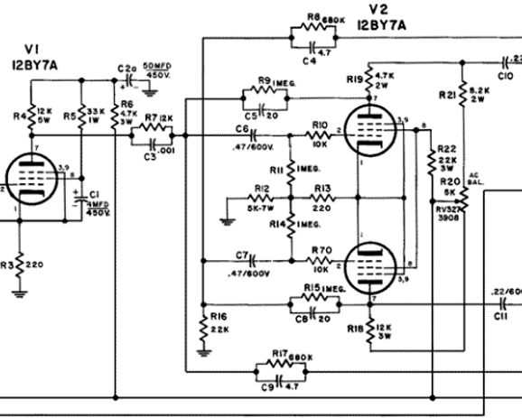
Citation MKII
I remember reading an article on this design by Hegeman in an electronics magazine from the late 50s or early 60s. His tone was strikingly bold and assertive, if not combative and aggressive. Perhaps, he had met much opposition to his design choices and he sought to silence his critics. Perhaps, on the other hand, he personality was, as my teenage kids would say, salty. Long ago, when the American magazine, The Atlantic, was not the literary equivalent of the National Enquire, its many-decade editor, Ellery Sedgwick, wrote:
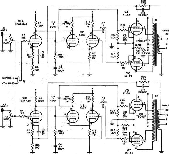
My reading of Hegeman was toasty and high. (Each month as a teenager, I read both The Atlantic and Harpers from cover to cover, something I cannot imagine anyone doing today, which is so sad.) Nonetheless, the amplifier is impressive to see, to lift, and to hear. I would give most of the credit of the last attribute to the output transformers, as they are excellent and only bettered by the Heathkit WM-6's, which were made by Peerless Transformers. (By the way, I own both amplifiers.) What troubled me was the lack of symmetry in part values. Here is a closeup that shows R7 not matching R16, and R19 and R21 defining a voltage divider, whereas coupling capacitor C11 attaching directly to the phase-splitter's bottom pentode's plate.
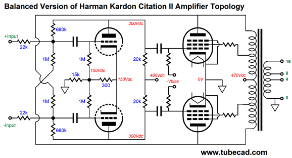
By feeding the phase splitter a balanced set of signals, rather than the single unbalanced signal allows us to impose balance. I am using triodes in the phase splitter both to avoid clutter and to appease my prejudices.
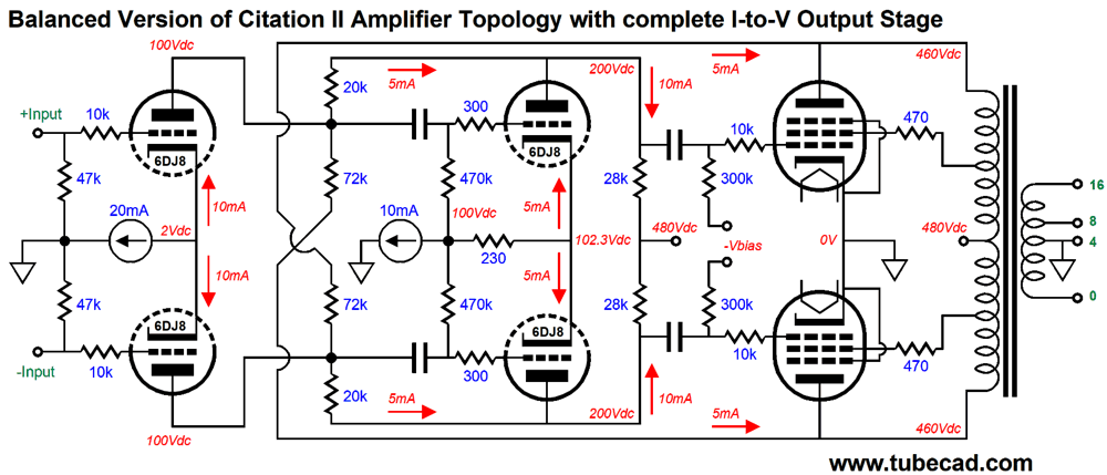
Next, we can add an extra gain stage and attach two global negative-feedback loops.
I would love to try something like the following, which confines all the negative feedback to the primary side of the output transformer.
As I mentioned earlier, I actually own a Citation II, so I could go to work on this project, but finding the time is next to impossible. Nonetheless, I like the look of this ultra-empathic design.
Check out post 305 for more on the concept.
Circlotron Output Stages
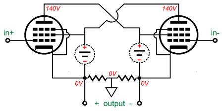
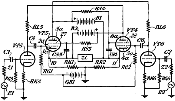
The key point is that pentode's grid-2 attaches to a fixed DC voltage, so true pentode operation obtains. Here is the C. T. hall's patent drawing.
Patent drawings usually suck, but this is still a lovely sight. I would love to have it emblazoned on a T-shirt or a coffee cup. Imagine it cross-stitched or needle-pointed on a white canvas and the schematic on display on your wall—wife acceptance factor be damned.
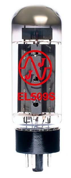
Today, it appears that only triodes are used, either the 6AS7 or the 6C33, in circlotron power amplifiers. Perhaps this is a mistake, a big mistake. How so? Power horizontal sweep tubes are a possible substitute for the triodes, as these power tubes were designed to do precisely what an OTL needs most: they pass high current. Futterman used the 6LF6 as an output tube; and JJ makes a version of the PL509 that does not hold a plate cap, which is vastly preferable, the EL509S. This 42W tube can pass a maximum cathode current flow of 500mA, which is four times more than the 6AS7's maximum. Moreover, its 6.3V heater only draws 2A, not the 2.5A of the 6AS7.
Now 100W into 8-ohms requires voltage swings of 40V peak and peak current swings of 5A, so it looks like we would need, in a 100W circlotron amplifier, twenty EL509S tubes per channel. Well, not quite. The EL509S can pass a peak current of 1.3A with a grid voltage of 0V and cathode-to-plate voltage of 100V. In comparison, a 6AS7 under the same conditions passes 550mA per triode. In other words, both tubes are closer in true peak current delivery, but differ in maximum plate dissipation, 42W versus 13W for each 6AS7 triode (the 6AS7 is a twin-triode design), making for a total of 26W per 6AS7. As long as we are playing music and not running a sinewave generator at full output, these peak current flows will be rare and brief. Organ music and synthesizer music need not apply.
Thus, we would need only eight EL509S output tubes for 100W of output power. That's if we went for pure OTL. What if we used either an autoformer or an output transformer with a ridiculously low winding ratio, say four to one. Such an inductive output device would reflect the 8-ohm load as 128 ohms to the output cathodes. A peak current swing of 1.3A into a 128-ohm load equals 108W. In other words, we could get away with just two EL509S tubes per channel. Alternatively, if we retained the eight output tubes, we could get 400W with an output transformer with a winding ratio of two to one. Bear in mind that the lower the winding ratio, the better the output transformer's performance, as the primary and secondary would couple much more tightly. In addition, an autoformer or output transformer is vastly safer than a naked, DC-coupled OTL, as arcing tubes will not short out across the loudspeaker. Moreover, an autoformer or an output transformer would allow us to use both 8-ohm and 4-ohm loudspeakers. Imagine if Mr. Hall could see a 400W version of his original design. Okay, let's return to pure-triode designs. I have shown before several circlotron versions that used nested negative feedback loops to linearize the output tubes. Well, I have new a variation on my design from post 429, but first the original.
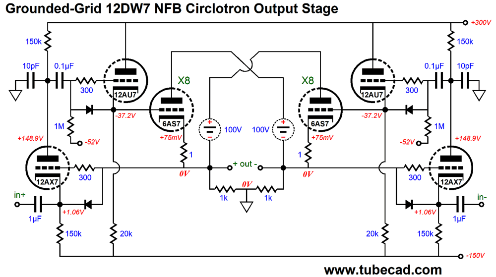
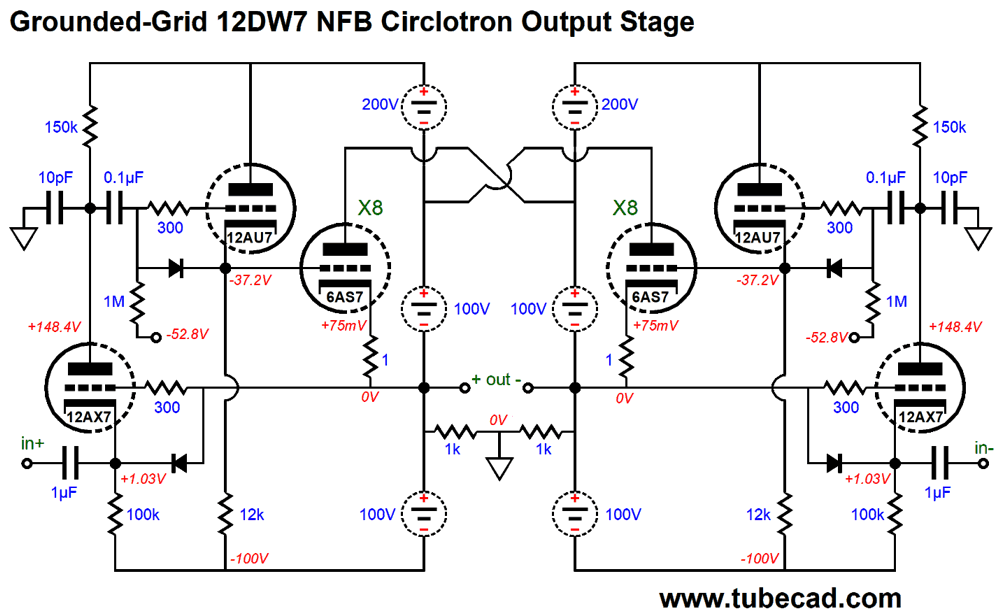
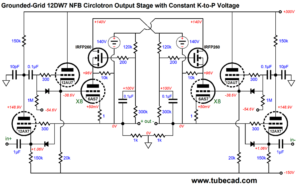
The grounded-grid amplifier accepts the input signal at its cathode and its grid monitors its output triode's cathode. In other words, the grounded-grid amplifier enslaves the output triode. If the grounded-grid amplifier delivers a gain of 10, we can expect about a tenfold reduction in output distortion and output impedance. This circuit works well in SPICE simulations, but I realized that SPICE was blind to a critical problem: positive-grid current flow. Sadly, most SPICE tube models do not include positive grid current flow. Yet positive-grid current sets a major limit to tube amplifier performance and output power. Think about it: if we drive eight 6AS7 triodes into positive grid voltages, the coupling capacitor will quickly become over charged, forcing a larger voltage drop across the coupling capacitor, which can result in blocking distortion, wherein the output tubes cease to conduct and no music reaches your ears until the coupling capacitor have discharged the excessive voltage drop, which can take seconds. The workaround is to use a DC-coupled cathode follower to drive the eight 6AS7 grids.
A 12DW7/ECC832 is shown. The DC-coupled cathode follower drives the grids directly, so there is no coupling capacitor that could charge up excessively. The input impedance at the 12AX7 cathode is about 25k, which is far lower than what its grid presents, but not too low. The 10pF capacitors prevent peaking at ultrasonic frequencies. Both the 12AX7 and 12AU7 triodes are powered by a separate fixed bipolar power supply. This setup allows us to use the single bipolar power supply with two channels. Making this bipolar power supply with dissimilar power-supply rail voltages is easy enough.
On the other hand, using two floating power supplies per channel offers better performance, as the grounded-grid amplifier and cathode follower effectively are loaded by constant-current sources, which increases their gain and decrease their distortion.
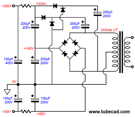
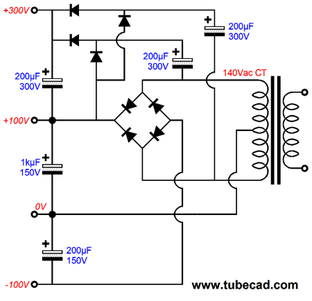
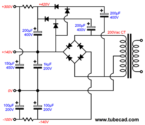
It looks complicated, but the idea is simple enough: two floating bipolar power supplies per channel, with only the center portion of power supply (from 0V to 100V) drawing heavy current. Here is how we get this power supply from a center-tapped secondary.
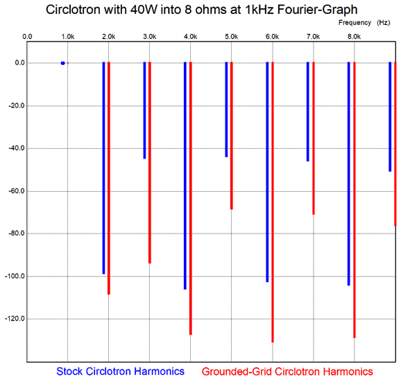
By the way, I used a 12DW7/ECC832 dissimilar twin-triode tube as an example, but, in reality, I would use a 12AX7 and ECC99. Still, with the 12DW7, SPICE simulation produced excellent results, far, far better than current production circlotrons. For example, the output impedance dropped from 7 ohms to 0.25 ohms. The improvement in THD was equally staggering 0.05% compared to 0.9% from the standard version.
Another huge improvement is the huge increase in gain. The naked, stock version required an input signal of +/-89Vpk to achieve 100W of output into 8 ohms; the grounded-grid amplifier version, only +/-21Vpk. I decided to redraw the schematic, as some prefer the following layout.
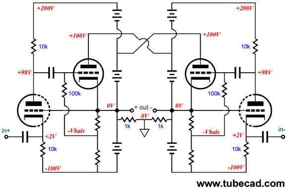
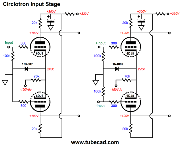
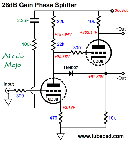
This layout better allows us to imagine the array of parallel output triodes. The grounded-grid amplifier's low input impedance (about 40k with the two floating negative power-supply rails) requires a robust input stage. Here are two possible circuits.
The circuit on the left is for unbalanced input signals, while the one on the right is for balanced signals. If we desire more gain, the following variation would work well.
The cathode follower's low output impedance is a better match than the differential amplifier's relatively high output impedance. As I look at this circuit, however, I believe that a more robust tube and a higher idle current might be needed in the cathode follower stage, say a 12BH7 or 5687 or ECC99. Here is another version.
The gain comes in at 1:20 (+26dB) and has been optimized for 40k loads. In other words, different load impedances requires a different Aikido mojo resistor value.
Constant-Cathode-to-Plate Voltage Circlotron
Ideally, we want the opposite to happen: when the output swings 40 volts, the output tube would see its cathode-to-plate voltage increase by 40V or more. I laid out the concept and possible designs in post 288. Here is a quote from that post.
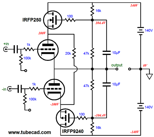
An alternative scenario would be a magic wallet that always held five twenties in it, no matter how many you took out to spend. In an OTL amplifier, the equivalent would be that the output tubes always saw a fixed cathode-to-plate voltage. Happily, this trick is easy to implement. Here is the totem-pole arrangement.
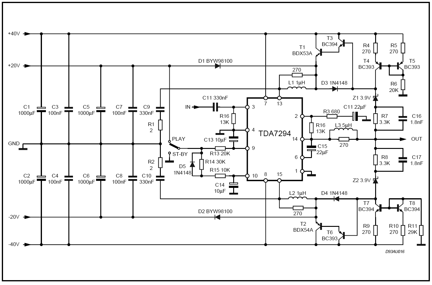
Note the 20k resistor that bridges both MOSFET sources. It is critical. Long ago, when I experiment with solid-state class-G output stages, I ran into headaches, as the switching between power-supply voltages created oscillations, which required snubber networks to tame. Here is an example of how one company tackled the problem.
Note the Darlington power-supply transistors (T1, T2, T3, T6) and the inductors (L1 & L2) and snubber circuits (R1, R2, C9, C10). Why are they there? When the power-supply transistors abruptly switch on and off they create oscillations that must be damped. My own workaround to the switching problem in class-G amplifiers was not to let the class-G power-supply transistors ever turn off. Thus, the inclusion of the 20k resistor, which prevented the MOSFETs from ever cutting off. No cutting off, no oscillations. A 20-cent solution. Here is a circlotron version, which uses two 10k resistors in place of the totem-pole's single 20k resistor. The result is the same, the MOSFET always draw some current. Since both sides are balanced, the load never sees the steady current flow from the resistors.
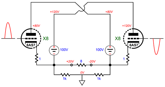
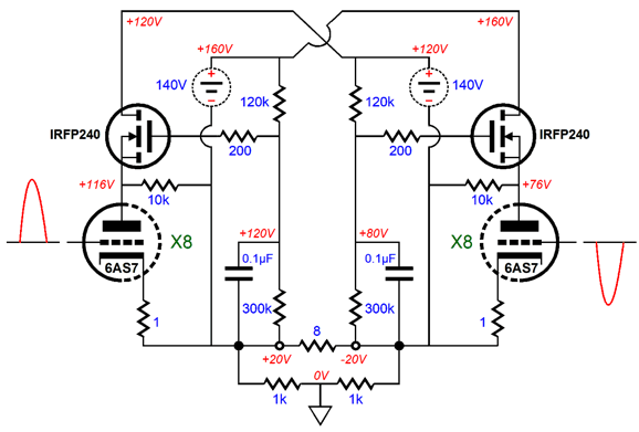
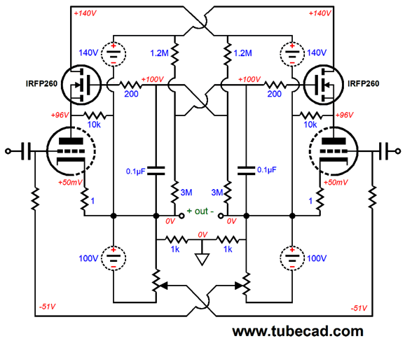
The two power MOSFETs are configured as source followers and function as capacitance multipliers. The capacitor does not terminate into ground, however, but into the output of the triode it feeds voltage to, which means that the MOSFET follows the output signal, resulting in a fixed cathode-to-plate voltage. If we use 1µF (or larger) capacitors instead, the plate voltage will come up more slowly, as the capacitors must charge up through the 120k resistors. Or we could use larger-valued resistors, say 1.2M and 3M. Here is an example of the circlotron putting out 100W and undergoing 40V peak output voltage swings.
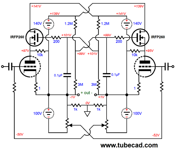
Above, we see the circlotron putting out +20V and -20V into the loudspeaker. The bank of triodes on the left see their plate voltage increase by 20 volts, but their cathodes also increase in voltage by 20V; the bank of triodes on the right see their plate voltage drop by 20 volts, but their cathode voltage also drops by 20 volts, making the cathode-to-plate voltage a constant for all triodes. In contrast, the MOSFETs see big changes in their source-to-drain voltages. At idle, the MOSFETs experience a 44Vdc voltage drop. However, at full output, i.e. 40Vpk and 100W into 8-ohm loads, each MOSFET will see its voltage drop fall to 4V and rise to 84V. In other words, by letting the triodes see a fixed cathode-to-plate voltage, the MOSFETs have taken on the burden of the big voltage swings. In addition, the two MOSFETs shield the sixteen triodes from the power-supply noise, as the MOSFET gates never see the noise. We can expect the two MOSFET used per channel to get hot, as all the triode currents flows through them. For example, if each triode idles at 50mA, each MOSFET must draw 0.4A, which against the 44V voltage drop results in a dissipation of 17.6W. Of course, this setup decreases the output stage's efficiency. No one ever said, however, that better performance was cheap, excepting a few million ads of course. What would the power supply look like?
Each channel requires two of these circuits. In addition, heating the eight heaters will require 126W of power, as 6.3V at 20A equals 126W. I would place four heaters in series and attach it to a 25.6V @ 2.5A DC power supply; two strings and two power supplies would be needed for each channel. The great advantage to this arrangement is that the rectification losses are a smaller percentage of the total dissipation. In addition, the wire need to hookup the heaters could be smaller in gauge. Of course, the obvious downside is that if one heater opens, we have the Christmas-tree-lightbulb problem of finding the bad tube. The workaround is to place an LED in series with a resistor and place this pairing in parallel with each heater element, so if one heater blows, we could easily find the lit LED and the bad tube. We can get fancier still by crisscrossing or garter-belting the the two sides of the circlotron.
The DC voltage crisscross, so the natural tendency to to self balance. Imagine a 2V DC offset, wherein the negative output was 1V positive; the positive output, 1V negative.
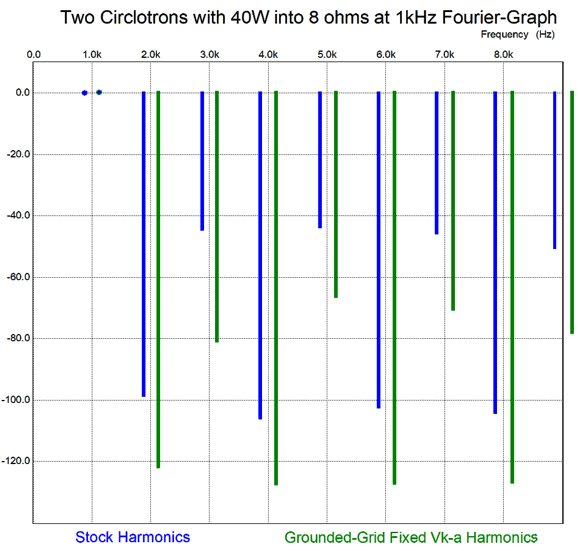
The DC crisscrossing of reference voltages bucks the DC offset, as right triode sees its grid-bias and plate voltage fall by -1V, while the left triode its grid and plate voltages rise by +1V. The big question left unanswered is: how well does this fixed-plate-voltage version of circlotron perform with the grounded-grid driver stage? The distortion is suitably low, as the 100W at 1kHz THD was 0.055% in SPICE simulations.
The output impedance came in at 0.23 ohms. But what these specifications miss is more subtle. For example, the conventional circlotron with cathode followers directly driving the 6AS7 grids sees those grids go 22.8V positive, while those in the fixed-plate voltage version only go 5V positive relative to the cathodes. Since the SPICE triode models do not include positive-grid current flow, we can only assume that 22.8V will prove far more wobbly than 5V. In addition, the N-channel MOSFETs radically improve what I call the dynamically-induced poor PSRR, which is the PSRR of the amplifier not at idle, but when one set of output devices shuts off. The Conventional circlotron's dynamically-induced poor PSRR came in at -15.7dB, while the fixed-plate-voltage version came in at better than -100dB. In other words, the real test must be performed with our ears.
Crowhurst Anti-Blocking Technique
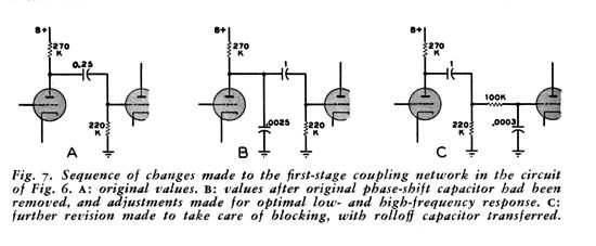
His first step is to remove the shunting capacitor from the negative feedback resistor. The next step is to use a large-valued grid-stopper resistor, as in 100k, and add a small-valued capacitor to ground to limit the output stage's high-frequency bandwidth. In other words, this added capacitor takes the place of the negative feedback loop capacitor.
Now, when the output tubes undergo positive-grid current flow, both the added capacitors and the coupling capacitors will charge up; the coupling capacitors will charge up negatively, the added capacitors, positively. The result is the output tubes never see their grid-bias voltage drop to the point of current cutoff, hence no blocking of the signal. Here are his own words:
This is an interesting approach. I can see where having a digital storage scope and pulse generator would come in handy in testing his solution.
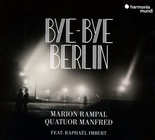
Music Recommendation: Bye-Bye Berlin The second thing to note is the album's title, which echoes. Berlin's in the 1920s was the stuff of Broadway musicals and Hollywood movies. An amazing place, an amazing time. Thus, this album, which seeks to capture its flavor and diversity, is long, just over an hour on CD. Amazon Music streams it at 24-bit/44.1kHz. Marion Rampal sings beautifully in English, French, and German. Many of the tracks are demo quality. Definitely worth hearing, if only once. //JRB
User Guides for GlassWare Software
For those of you who still have old computers running Windows XP (32-bit) or any other Windows 32-bit OS, I have setup the download availability of my old old standards: Tube CAD, SE Amp CAD, and Audio Gadgets. The downloads are at the GlassWare-Yahoo store and the price is only $9.95 for each program. http://glass-ware.stores.yahoo.net/adsoffromgla.html So many have asked that I had to do it. WARNING: THESE THREE PROGRAMS WILL NOT RUN UNDER VISTA 64-Bit or WINDOWS 7 & 8 or any other 64-bit OS. I do plan on remaking all of these programs into 64-bit versions, but it will be a huge ordeal, as programming requires vast chunks of noise-free time, something very rare with children running about. Ideally, I would love to come out with versions that run on iPads and Android-OS tablets.
//JRB
|
|
I know that some readers wish to avoid Patreon, so here is a PayPal button instead. Thanks. John Broskie
John Gives
Special Thanks to the Special 86
I am truly stunned and appreciative of their support. In addition I want to thank the following patrons:
All of your support makes a big difference. I would love to arrive at the point where creating my posts was my top priority of the day, not something that I have to steal time from other obligations to do. The more support I get, the higher up these posts move up in deserving attention. If you have been reading my posts, you know that my lifetime goal is reaching post number one thousand. I have 487 more to go. My second goal was to gather 1,000 patrons. Well, that no longer seems possible to me, so I will shoot for a mighty 100 instead. Thus, I have 14 patrons to go. Help me get there.
Only $12.95 TCJ My-Stock DB
Version 2 Improvements *User definable Download for www.glass-ware.com |
||


| www.tubecad.com Copyright © 1999-2020 GlassWare All Rights Reserved |