| John Broskie's Guide to Tube Circuit Analysis & Design |
| Post 212 27 August 2011 RIP Bob Pease & Jim Williams
Cathode Followers
Where to start? Rather than recreate from memory what I have written before, here is a snippet from the user guide to my Tube CAD program:
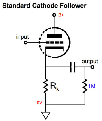
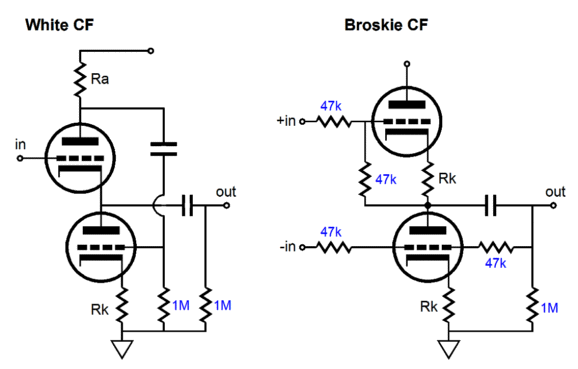
The old textbook approach was to use a cathode resistor five times smaller in value than the load being driven; for example, for a 100k external load, use a 20k cathode resistor. Another trap is assuming that cathode followers are great for driving capacitive loads; they aren't, as they work much better at driving purely resistive loads. Back in the 1950s, tests were performed that showed if a grounded-cathode amplifier were configured with plate resistor whose value match the Zo of the equivalent cathode follower, then it outperformed the cathode follower at driving a capacitor at high frequencies. (Whenever I expect encounter a highly-capacitive load, I place a series resistor at the cathode follower's output, thus preventing the cathode from seeing the naked capacitance; and I always ensure that the idle current is robust enough to ensure adequate slew-rate.) And never forget that a cathode follower can never symmetrically swing more current into the external load than its idle current draw, as it is strictly confined to single-ended operation; for example, if it idles at 1mA, then it can only swing 0.6Vpk into a 600-ohm load and even that 0.6Vpk will not be pretty. After a while, these simple rules and guidelines become habit and designing a good cathode follower becomes second nature. In other words, if you are careful, you can easily get excellent performance from a cathode follower. This doesn't mean that the stock cathode follower cannot be modified or improved. For example, we can replace the cathode resistor with a constant-current source, either a tube-based or solid-state effort—or even an inductor. We can create a push-pull version by placing two tubes in series and using either the White cathode follower or the Broskie cathode follower topology.
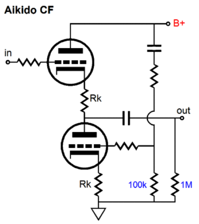
Or we could retain the single-ended operation and use the Aikido cathode follower topology, which will null power-supply noise at its output.
The Aikido cathode follower samples the noise at the B+ and then applies a countering variation in current flow to null the noise at its ouput.
Hybrid CF+
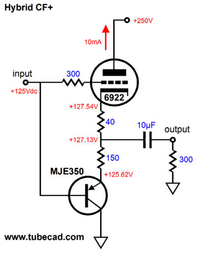
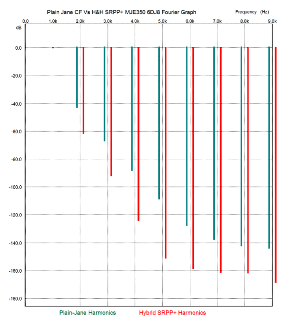
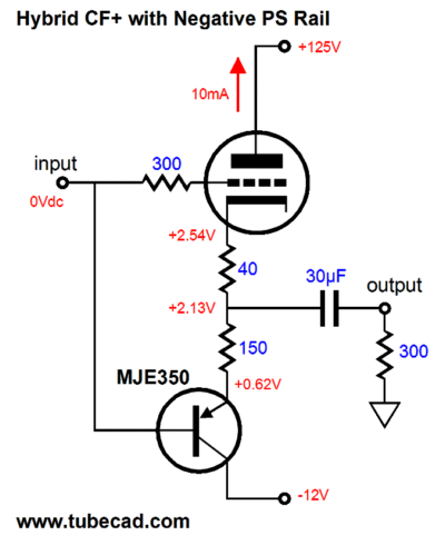
No, I didn't think so. First go through all the voltages to reassure yourself that it could bias correctly. Second, note that both triode and PNP transistor will operate in anti-current phase to each other. In other words, a positive input voltage will increase the triodes current conduction, but reduce the transistor's. The least obvious aspect is the two resistors that span between the cathode and the collector. Why two resistors and not just one? Well, 99% of tube gurus would use just one resistor (which in itself is enough to make me nervous). In a push-pull circuit, we want to ensure equal current swings from both output devices. But the beefiest triode is no match for the wimpiest transistor in terms of transconductance. So, the 150-ohm resistor not only helps bias the triode, it serves to undo much of the transistor's gm, so that matches the triode's with the 40-ohm cathode resistor in place. How well does this push-pull follower work? Here is a shootout in SPICE between a plain-Jane cathode follower and the hybrid CF+.
The test was 1Vpk a@ 1kHz into 300 ohms. Yes, the hybrid CF+ offers lower distortion, a lower Zo, and higher gain (a closer approximation to to true unity gain). Yet the hybrid CF+ has no less a single-ended sonic signature, as the above graph reveals. Pause and consider this interesting aspect of the hybrid+ circuit: the transistor does not need to displace the same amount of voltage that the tube must and which a big cathode resistor certainly would. Unlike tubes, transistors can work with just few volts across them.
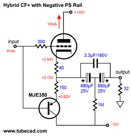
Not only do we save on B+ voltage and extra heat, we now can use lower-voltage parts, which are both cheaper and more volumetrically efficient. For example, say we planned on driving 32-ohm headphones instead. The problem with the high-voltage version is that we would have to use a high-voltage, electrolytic coupling capacitor, as we would need at least 300µF. Such caps are expensive, frail, and clunky. In contrast, with the above circuit and a 32-ohm load, we could use a super-high-quality Panasonic non-polarizied electrolytic coupling capacitor, such as the ECEA1CN331U. Even if we choose to further improve the signal transfer by adding a film bypass capacitor, a 160V film capacitor will cost much less and be much smaller than the same capacitor in a 250V form. I would also try something along these lines:
High-quality electrolytic capacitors are used back to back, with the 1M resistor biasing the capacitors up (or is down?). Furthermore, low-voltage transistors are readily available. Moreover, the hybrid CF+ is not confined to SE operation, as either tube or transistor can force huge current swings far beyond the idle current. In other words, class-AB operation. Where the plain-Jane (by the way, all the women named "Jane" I have met have been very nice looking indeed) cathode follower is limited, is to its idle current. Thus, if it idles at 10mA, then it could only swing 3Vpk into a 300-ohm load; the hybrid CF+, on the other hand, can swing an easy 6Vpk or much more into the 300-ohm load. How much more? It depends on the triode, the B+ voltage and the load impedance. Here is a quick formula: Ipeak = B+/(rp + Rload). The formula assumes that we stop at zero grid volts (relative to the cathode). For example, with an rp of 2700 ohms and B+ of 120Vdc and 300-ohm load, the peak current flow into the load would be 40mA, which against 300 ohms equals 12Vpk. Of course, our circuit could not meet this goal, as the negative power supply rail is only -12Vdc; and the 40-ohm resistor would have to be added to the 2700 + 300 ohms sum. Here is one last variation on the hybrid CF+, which uses an additional transistor to drive the PNP transistor's base and to give us an additional 0.7Vdc with which to bias the triode, as shown below.
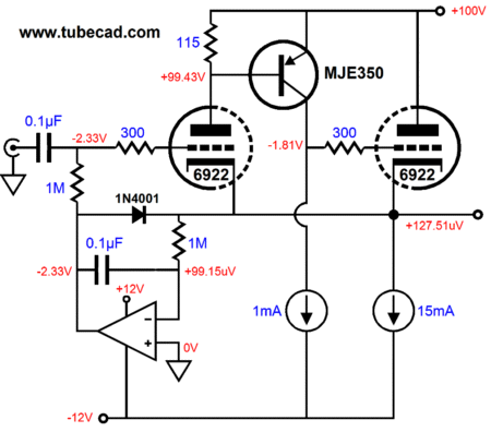
We can get away with just one resistor between the MJE350 ad the 6922, as the ensuing idle current is not excessive. If it were, then we would use the two-resistor approach. Although a 200Vdc B+ voltage is shown, we could use one with only, say, 110Vdc, while still giving the triode the high voltage it requires and letting the transistor make do with the remainder. And yes indeed, we could use a 100Vdc B+ voltage and a -12Vdc negative power-supply rail for both the transistor and the tube's heater element (with a 12V heater tube, such as the 12BH7, 5687, or ECC99). This arrangement would also allow us to DC-couple the input at ground level. Okay, if even just one transistor is too much, then we could dig back into blog number 186, where we find the Broskie buffer circuit:
I didn't make too big a deal of this circuit, as I was hot on the trail of the Tringlotron. Nonetheless, the Broskie buffer is an amazing circuit. It is an augmented cathode follower that uses another triode to control the output triode, thereby greatly reducing the distortion and output impedance. Understanding how this buffer works will help you understand how the following buffer works.
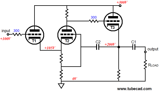
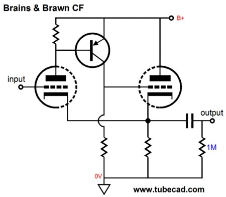
Brains & Brawn Cathode Follower
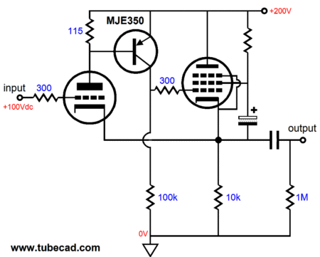
No doubt it is a bit confusing. What is that transistor doing there, for example; and are there no internal coupling capacitors? At first glance, it appears as if both triodes are driving the cathode resistor and the external load, but actually the input triode pretty much draws a constant current, which means it cannot directly dump a varying current into the load. That job is held by the right triode, which gets its instructions from the input triode, the brains of the circuit. The transistor's sole job is to maintain a constant current flow through the input tube. It does so by striving to maintain a fixed voltage across the resistor at its base and emitter. If the voltage drop across the resistor increases, the transistor's current conduction increases as well, which develops a more positive voltage at the output triode's grid, which in turn will prompt an increase current through this tube and its cathode resistor, forcing the input triode's cathode more positive, thereby decreasing its current conduction, restoring the fixed voltage across its plate resistor. In other words, this buffer will fight to keep its output in line with its input signal. Nonetheless, I know that many (even recent EE graduates) just don't get transistors. Since we have tubes and OpAmps, why bother with single transistors. Okay, I feel your discomfort, so here is effectively the same circuit, but sans transistor:
The transformer's primary senses any variation in current flow and will create a voltage swing at its secondary, should it encounter a current variation. The output triode sees at its grid the induced voltage swing and its cathode follows as a result. Once again, this buffer will fight to keep its output in line with its input signal. The electrolytic capacitor can probably be removed altogether or replaced with the following setup. The transformer's secondary should see a resistor across it, but I didn't want to clutter up the schematic.
If the transformer held two secondaries, then we could create a push-pull output stage, with one secondary winding driving the bottom tube and one driving the top tube. The bottom triode's secondary winding would be arranged in anti-phase to its top brother.
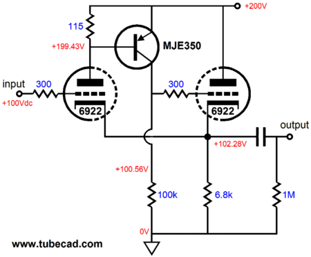
Note that both the top and bottom output tubes are configured as grounded-cathode amplifiers, not cathode followers. What?! The circuit as a whole is a unity-gain buffer, but the the two output tubes are configured as grounded-cathode amplifiers, as they do not see any cathode degeneration other than the small degeneration provided by the unbypassed cathode resistors. Back to single-ended operation. Below, we see all the part values filled in; and, of course, different tubes and a different PNP transistor could be used.
The important feature to note is that the input tube does not have to draw the same current as the output triode, nor even be the same type of triode. This means that dissimilar tubes, such as the 12DW7 can be used. In fact, triode and pentode dual tubes, such as the 6AN8 and 6BM8, can also be used. Or we could use one tube type for the input triode, such as 6N1P and an EL84 for the output tube.
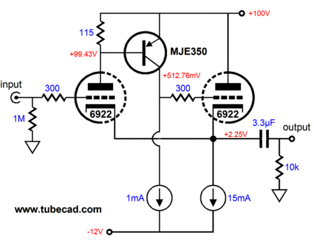
By adding a negative power-supply rail and two constant-current sources, we can accept ground-potential input signals, à la No-Gain-No-Pain.
The coupling capacitor is essential, as 2,250 mV is one heck of a DC offset. Much worse, in fact, is that at start up the tube will be cold and not conducting, so both cathodes will be at some negative voltage close to -12Vdc. Not good. Okay, what if we add a DC servo loop? Can't we then lose the coupling capacitor?
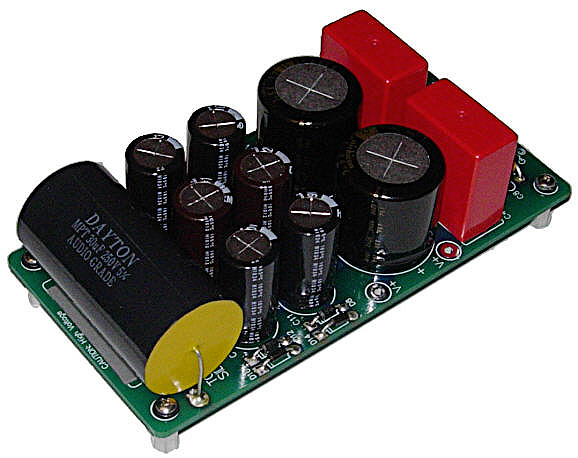
Yes, we can lose the coupling capacitor, but only if we add a relay and its complicated voltage sensing and evaluation circuitry to the output or the five-cent diode in the schematic above. I like diodes, but most solder slingers believe that their use is restricted to the power-supply portion of a circuit. Wrong. In this example, the diode only becomes forward biased (i.e. conducts), when the OpAMp's output voltage becomes more than 0.7Vdc more positive than the B & B CF's output, which would only happen if the tube failed or was absent or cold, as once the tubes are hot, their cathodes will be at some voltage more positive than their grids. In other words, the diode acts as a safety net, pulling the B & B cathode follower's output up to 0Vdc when something has gone wrong. Five cents wisely spent, no? (I used to know this brilliant Russian analog electrical engineer, Vladimir, with whom I exchanged circuits. He was fantastically creative because he was profoundly cheap. I remember him looking over my latest high-voltage regulator and him saying, "Diodes! Diodes everywhere. Why so many diodes?" I knew he resented the cost and my answer was that they cost five cents each and they kept the regulator from catching on fire. He pondered this for a bit and then proclaimed, in an impossibly low Russian accent, "Okay, eeze good idea.") By the way, the above circuit looks like a natural for the PS-6 power supply, which offers a bipolar low-voltage power supply and a mono-polar high-voltage output that is five times greater than its rail voltage. For example, if the PS-6 is attached to a 28Vac center-tapped secondary and puts out +/-20Vdc as result, then its HV B+ output voltage would be 100Vdc.
The 20 volt rails could then see two 12V or 15V three-pin regulators.
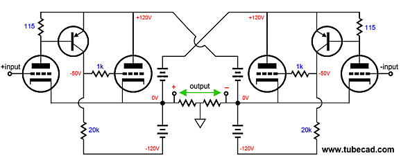
B&B Circlotron
Think 6AS7 or 6C33 and imagine many of them. The problem the circlotron faces is that the tubes most likely to be used are not very linear, nor do they provide a sufficiently low output impedance. The above circuit will correct both those problems. (If actually built, the above circuit will exhibit a slight DC offset—the same on both outputs—that we can ignore, or adjust the circuit to eliminate.)
Next Time
//JRB |
I know that some readers wish to avoid Patreon, so here is a PayPal button instead. Thanks.
John Broskie
E-mail from GlassWare Customers
High-quality, double-sided, extra thick, 2-oz traces, plated-through holes, dual sets of resistor pads and pads for two coupling capacitors. Stereo and mono, octal and 9-pin printed circuit boards available.  Aikido PCBs for as little as $24 http://glass-ware.stores.yahoo.net/
Support the Tube CAD Journal & get an extremely powerful push-pull tube-amplifier simulator for TCJ Push-Pull Calculator
TCJ PPC Version 2 Improvements Rebuilt simulation engine *User definable
Download or CD ROM For more information, please visit our Web site : To purchase, please visit our Yahoo Store: |
|||


| www.tubecad.com Copyright © 1999-2011 GlassWare All Rights Reserved |