| John Broskie's Guide to Tube Circuit Analysis & Design |
28 July 2006 I had hoped to post at least once from the East Coast, but never got the chance. Most of my computer time was wasted trying to access my email from a succession of phone numbers (dialup! I’ve been so spoiled by DSL.) In addition, the “Nothing Ships Until I Get Back” Sale was a big hit – so big, in fact, that I was kept busy with the orders for the whole week since I got back. (Thanks for the interest and congratulations. As I put together the packages, I kept thinking about how many new Aikido fanciers were about to be created.) So while a number of topics have been swirling around in my head, this is my first chance to flesh one out. I’ve chosen the one that tickles me most: Einstein’s amplifier. Don’t be confused. A year and a half ago, I labeled an amplifier topology the “Einstein amplifier.” I chose that name partly because the amplifier shifted the usual frames of reference, creating a single-ended amplifier that looked like it was standing on its head; but mainly because the design was born of an Einstein mental algorithm, wherein instead of fighting your biggest problem, you make what had been the problem the first principle of your new system. But now I’m not talking about that “Einstein amplifier.” What I’m talking about here is Albert Einstein’s actual power amplifier. The real Einstein amplifier
Einstein's amplifier
So, what sort of audio system did Albert listen to at home? The partial answer comes from reader Allen:
The topology 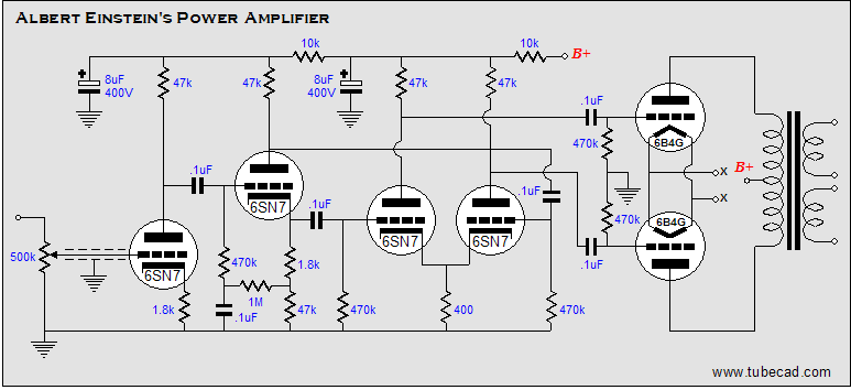
The only twist is found in the addition of the RC (the 1M resistor and 0.1µF capacitor) filter at the bottom of the split-load phase splitter. Not a good idea. My guess is that it was added in an atempt to re-balances the phase-splitter's output, which was thrown off because of the 1.8k cathode resistor (the 1M resistor is effectively in parallel with the bottom 47k resistor). A better ploy would be to ommit the 470k resistor and the 0.1µF capacitor, while moving the bottom output to below the cathode resistor, as shown below. 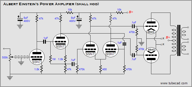
I like the 6SN7s and the DHT push-pull output stage (the 6B4G is a 2A3 type tube with an octal base and a 6.3 filament) and the absence of a global feedback loop and the use of octal tubes; but nothing really fresh or inspired stands out. Not that this is bad amplifier design, it just doesn't appear that novel today, maybe it was more so in 1949. Although I would be surprized if it was. In fact, below are some other designs amplifier designs circa 1950, which illustrate how similar amplifiers were being designed at that time: 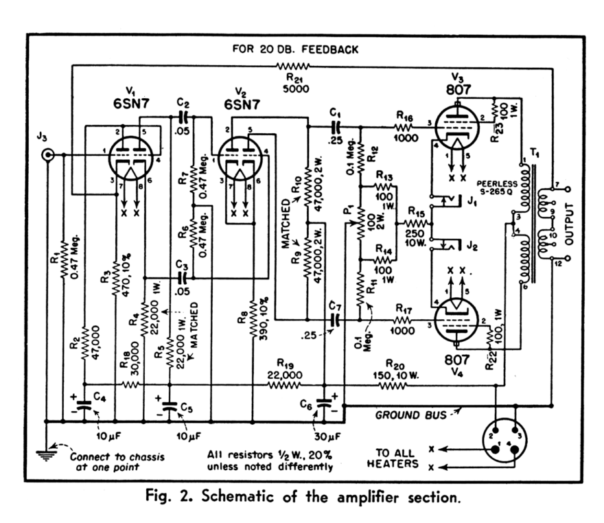
The above amplifier is from Audio Engineering (1949) and the amplifier below is from High Fidelity No 48, a book from the Gernsback Library (1953).
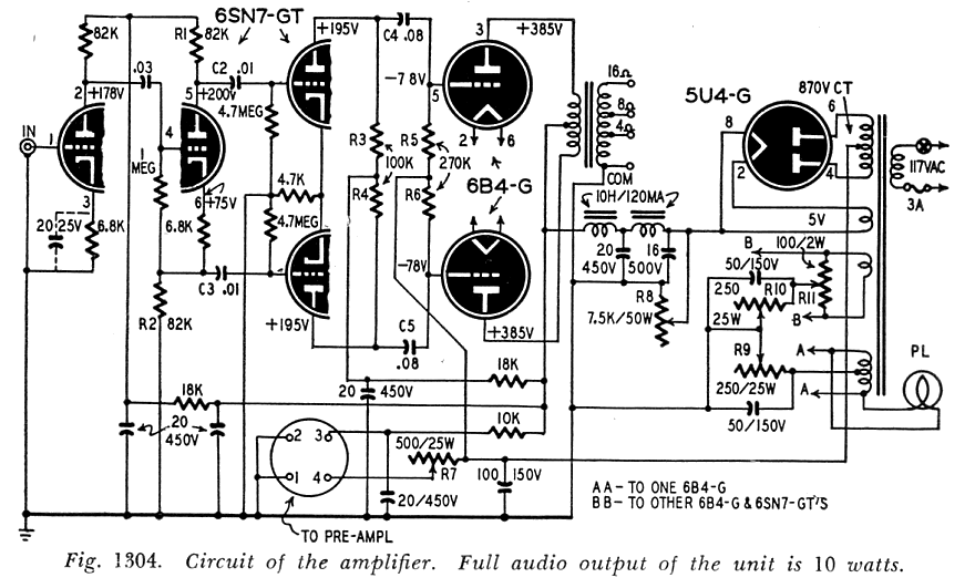
The first amplifier used a feedback loop, the second didn't. Nonetheless, I am sure that with quality iron, good tubes, and good coupling capacitors, the Einstein amplifier would sound quite good today. Therefore, I wouldn’t tweak/modify/improve/fix anything on the amplifier or leave anything out; instead I would build it straight off the schematic. Why? Because that way you would have an excellent conversation piece. Einstein’s tube power amplifier, what could be snazzier? Definitely, be sure to pick up a copy of Make magazine (Vol. 06) and look at the beautifully built amplifier on page 192. Mercy.
Make magazine
“DIY porn” was an apt description. Make magazine is devoted to existing mechanical and electronic hardware hacking and to new DIY designs. It is a slick effort, unlike Sound Practices and most underground magazines; it is sumptulously laid out, with high-quality color photos and professional illustrations, and almost no ads. No, it's not a cheesy, ad-ridden, weak-kneed magazine that will end up in the recycle box an hour after receiving it; nor is it cheap at $14.99 a copy, but it is worth it. Really, it belongs on your bookshelf next toissues of Audio Technology, MJ and Morgan Jones's books. Its motto is “Technology on your time.” and the magazine sells T-shirts that read, “If You Can't Open It, You Don't Own It” and “Void your warranty, violate a user agreement, fry a circuit, blow a fuse, poke an eye out...” However, it is not an audio magazine. First of all, its editor and writers are not over 60 (nor is anyone obviously anal-retentive, twitchy, sycophantic...). Many issues of Make may come before an audio-related, let alone a tube-related, article shows up again. Follow this link to see the current issues table of contents.
Aikido-inspired amplifier for Einstein 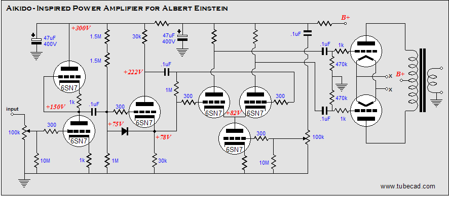
It's Aikido time! Three audio Aikido techniques allow this amplifier to sidestep power supply problems (only two are shown in the above schematic). The input stage consists of a grounded-cathode amplifier with a symmetrical loading of the same tube and cathode resistor value. This stage then cascades into the split-load phase splitter. Because the first stage evenly divides the power supply noise, the phase splitter passes this noise equally between its two output phases, which means that the following differential amplifier will reject most of the noise because of its inherent CMRR. Additionally, the first two stages work in opposite AC signal current phase, so that the simple RC filter at the B+ has much less work to do, as it does not see the audio signal. Second, the differential amplifier finds an active cathode load in the bottom triode and its cathode resistor. This triode effectively equals a medium-sized cathode resistor. But as the triode’s grid samples some of the B+ noise, the power supply noise at the differential amplifier’s outputs can be nulled. The last Aikido technique is to introduce a small amount of B+ noise to the cathodes of the output stage, via an additional capacitor, which will null the noise at their plates. For output tubes, choose 2A3s or 6B4s or 300Bs. I would use a rich class-A idle current and take the sweet sound over the lost watts.
Next time
//JRB
-----------
|
|


| www.tubecad.com Copyright © 1999-2006 GlassWare All Rights Reserved |