| John Broskie's Guide to Tube Circuit Analysis & Design |
|
06 May 2007
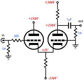
Common-cathode (a.k.a. cathode-coupled) amplifier I do not want to recap the basics of the circuit any further here, as I have covered that aspect of the topology before. See blog 42 for more background. (I suffer from a quirk: I cannot stand anything I have written--well, I can't stand it right after I have written it, to be exact. After I have finished writing, I always feel that I have done no more than just sketched out the roughest first draft and that a lot more work is needed. But after a year or so passes, I look back on the once-hated piece of writing with a small smile. So it was when I reread blog 42: “not bad, not bad at all” was my fond observation.) The last blog entries mentioned the trick of making cathode followers on the cheap. Long story, short: don't use a negative power supply. Instead, rely on a low-mu triode and a high B+ voltage to allow a higher cathode voltage and, in turn, a larger-valued cathode resistor, largely bypassing the need for a negative power supply rail. Well, the same trick can be applied to a common-cathode amplifier, as shown below:
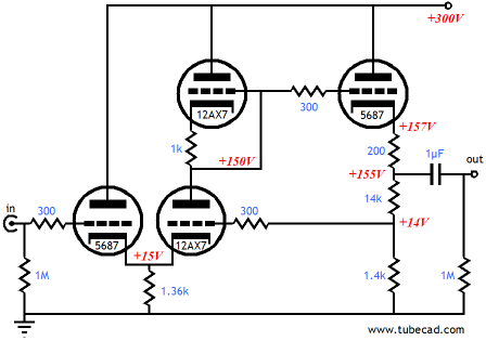
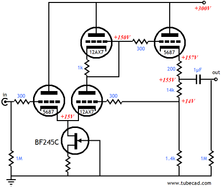
The 5687’s low mu (about 17) and the B+ voltage of 300V requires a -15V grid-to-cathode voltage to maintain an idle current of 10mA. A 1Vpk input signal is only 1/15th as large, which means that the triode will only have to undergo a small change in current conduction to accommodate the input signal (10mA/15). So, while a negative power supply and a much larger cathode resistor will produce less distortion, the 1,500-ohm cathode resistor isn’t that much worse. (1,360 ohms is shown in the schematic, because the 12AX7’s current conduction must be factored in the resistor’s value.) Note that 5687 triodes are not used throughout; instead, a 12AX7 receives its input signal at its cathode from the input 5687’s cathode. Then this bottom 12AX7 is loaded at its plate by another 12AX7, which helps lower its distortion, as the symmetrical loading offers a countervailing twist to an already twisted active circuit element. [I changed my mind; see Blog 107 for details] The rest of the topology falls into place, with the second 5687 delivering a low-distortion and low-output-impedance in the cathode-follower-based output stage. The output triode's cathode resistor is made up of three sub-resistors, which works as a voltage divider to present the feedback to the bottom 12AX7’s grid. The total gain is roughly +20dB (1:10); the open-loop gain is closer to +34dB (1:50). Much like the Aikido circuit, this line stage amplifier will require a heater power supply that is referenced to ¼ of the B+ voltage, in this example, +75V. The power supply must be well-filtered or regulated, as this topology does not enjoy any Aikido techniques to sidestep the power-supply noise. Still, this is an interesting circuit and I wish I had time to throw a working example together. Of course, the 5687 and 12AX7 are not the only tubes that can be used; two 5687s or two 6SN7s can be used instead, or a 6BX7 and 6SL7 might make a good pairing as might a 5751 and two 12B4s. In fact, a negative power supply rail can be added or, what might be better still, a FET-based constant-current source could be used, which would not require the bipolar power supply. (The source resistor's value must be adjusted to yield an idle current of 11mA through the FET.)
Wait a minute. How does this circuit sound? Well, with the right records or CDs, it sounds a lot like Beethoven or Chopin or The Beatles or John Coltrane or Rosa Passos. No, no, not what is it playing, but What does IT sound like? Oh, I misunderstood. It sounds as clear as “Those eyes, with clearest substance crystalline,” as Barnabe Barnes put it in his sonnet number 103. But then, the more I think about it, Shakespeare, as always, said it better, as we read in his 103rd sonnet: Alack, what poverty my muse brings forth, In other words, I lack the skills to describe such audio perfection, so rather than "doing me disgrace" or having my words mar a perfect sonic presentation I leave it to you to listen and tell us what it sounds like.
Slew rate Here is an example of how the math will lead you astray (or should I have said too little math...). Yes, 600 ohms shunted by 1,000pF does equal a 265kHz transition frequency, if the amplifier driving the 600-ohm resistance is burly enough to supply the needed current. How much current? It depends on how much voltage you wish to swing; 10Vpk into 1,000pF at 265kHz requires 16.7mA; 10kVpk into 1,000pF at 265kHz, on the other hand, requires 16.7A. (Hold a tiny 1,000pF capacitor in your hand and imagine dumping 16.7A of current into it.) In fact, the 12AX7-based cathode follower, with an idle current of 1mA, can only swing 10Vpk into a 1,000pF load up to 16kHz, thereafter it is slew limited and it distorts grossly. Remember, slewrate equals current divided by capacitance, SR = I/C. Now, a 12AX7-based plate follower will suffer the same fate with an idle current of only 1mA, as the same physics apply.
Plate followers
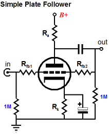
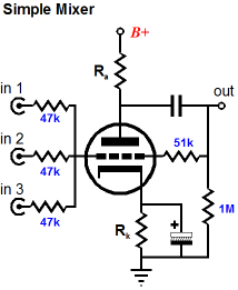
I know that more than a few readers are thinking right now that, other than the higher gain, the cathode follower has it all over the plate follower, as the cathode follower is simpler, uses fewer parts, does not invert the phase, and offers a high input impedance. While there is a lot truth to that position, the complete story is a bit more complex. For example, one liability the cathode follower faces is that its cathode is often floating far above ground, which makes referencing its heater to ground problematic, if the maximum cathode-to-heater voltage is exceeded. Moreover, the plate follower’s seeming liability of inverting the phase is not always a liability, as sometimes it is essential. In addition, the plate follower can easily be reconfigured as a mixer circuit or summing circuit by just adding a second input resistor; and its two feedback resistors allow easy frequency-selective attenuation or boost. In other words, the plate follower offers quite a bit more flexibility, which the cathode follower denies us. For example, what if we do not want 100% feedback, but only 15%? With a cathode follower we are out of luck, but with a plate follower, we need only set the appropriate feedback resistors ratio.
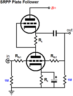
So, what can be done to improve the plate follower? Since the simple plate follower is—at heart—a grounded-cathode amplifier with a feedback loop, we can use the same techniques that improve a grounded-cathode amplifier’s performance. For example, the plate resistor can be replaced with an active load, as shown below. This modification yields a lower distortion and a better PSRR figure, as the active load effectively equals a much larger impedance than the plate resistor offered.
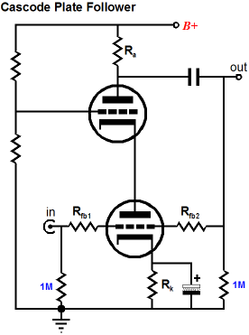
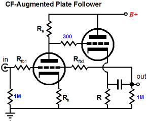
(I get depressed thinking about the 90% of tube fanciers who will label the above circuit as an SRPP, but at least I know that all the regular readers of this blog know much better, seeing immediately that this circuit functions in a pure single ended fashion, with no pushing and pulling.) Since we have moved onto two triodes, let see how many two-tube topologies can be rendered as plate followers. As shown below, a cascode amplifier can be retrofitted and transformed into a plate follower type circuit. Is this a good idea? I am not sure. The elimination of Miller-effect capacitance is a great advantage, as is the preservation of the bottom triode’s transconductance. But would two triodes in parallel work better? More experimentation is required
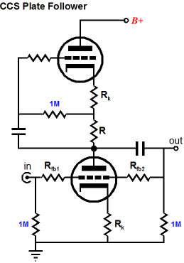
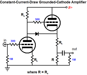
If the feedback resistors are removed, the circuit looks similar to the constant-current draw grounded-cathode amplifier that I like so much, as shown below.
This arrangement draws a fairly constant current, which greatly eases the power supply’s workload. Adding the two feedback resistors gives us the following circuit. 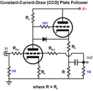
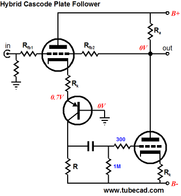
I know that the extra cathode resistor is bothering a few of you, but I would never build this circuit without it, as the small-valued resistor does wonders to improve the output tube’s linearity and it buffers the cathode follower’s cathode from excessive load capacitance. What else can two triodes do? The following circuit is an interesting example. The underlining configuration for the input tube is cascode, as the top triode sees a fixed cathode-to-plate voltage and the current variations that flow through it are relayed to the load resistor through the transistor. The output tube’s circuit topology is simply a variation on the grounded-cathode amplifier, albeit with a bipolar power supply. Expect a lot of open-loop gain, as the cascode will develop a high gain which the grounded-cathode amplifier will further amplify.
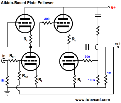
No doubt that a fistful of three-triode plate follower topologies can be devised, but I am jumping ahead to four-triode designs. the Aikido amplifier accepts the feedback loop gracefully and adds its superb power supply noise rejection and low distortion and output impedance.
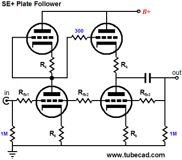
Ideally, in the SE+ plate follower, the output stage works in pure single ended operation, as the two feedback resistors, Rfb2 and Rfb3, notch out any drive signal, leaving only the output distortion as an input signal for the rightmost bottom triode’s grid, which will become inverted at its plate, reducing distortion at the output. The trick is to get the resistor ratios suitably adjusted, which means that this plate follower variation must work into a specified load impedance (or the ratios will be thrown off).
Next time //JRB
|
High-quality, double-sided, extra thick, 2-oz traces, plated-through holes, dual sets of resistor pads and pads for two coupling capacitors. Stereo and mono, octal and 9-pin printed circuit boards available.  Aikido PCBs for as little as $24 http://glass-ware.stores.yahoo.net/
Only $19.95
Download or CD ROM www.glass-ware.com
The TCJ Stepped Attenuator The center knob controls both channels, and offers six large decrements; the flanking knobs offer six fine decrements for each channel, creating a volume control and balance control in one easy-to-use stepped attenuator. This clever attenuator uses fewer resistors (only 32) than would be expected from a conventional 32-position stepped attenuator, as two series attenuators would need a total of 72 resistors; and two ladder attenuators would require 140 resistors. In addition, the PCB holds dual sets of resistor pads, one wide and one narrow, so that axial (composition, wire-wound, and film) and radial (thick-film and bulk-foil) resistors can be used without extra lead bending. Although designed to go with the Aikido amplifier, it can be used anywhere a high-quality attenuator is needed, whether passive or active. For example, it would make a first-rate foundation to an excellent passive line box. Visit our Yahoo Store for more details: http://glass-ware.stores.yahoo.net/
The Tube CAD Journal's first companion program, TCJ Filter Design lets you design a filter or crossover (passive, solid-state or tube) without having to check out thick textbooks from the library and without having to breakout the scientific calculator. This program's goal is to provide a quick and easy display not only of the frequency response, but also of the resistor and capacitor values for a passive and active filters and crossovers. TCJ Filter Design is easy to use, but not lightweight, holding over 60 different filter topologies and up to four filter alignments: While the program’s main concern is active filters, solid-state and tube, it also does passive filters. In fact, it can be used to calculate passive crossovers for use with speakers by entering 8 ohms as the terminating resistance. Click on the image below to see the full screen capture.
Tube crossovers are a major part of this program; both buffered and un-buffered tube based filters along with mono-polar and bipolar power supply topologies are covered. Available on a CD-ROM and a downloadable version (4 Megabytes). Download or CD ROM
|
|||


| www.tubecad.com Copyright © 1999-2007 GlassWare All Rights Reserved |