| John Broskie's Guide to Tube Circuit Analysis & Design |
| 21 September 2014 New All-in-One Power Supply
Sadly, the PS-10 kit is no longer available. But much of what I detail is still of interest to some. PS-10: All-in-One Tube Power Supply
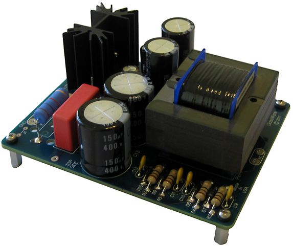
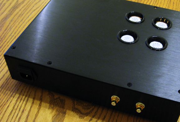
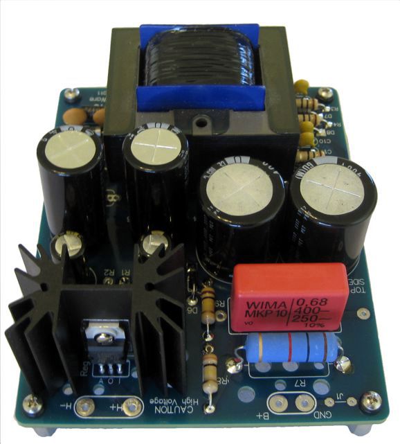
Everything except the tube sockets are soldered to the bottom of the PCB, as the PCB stands atop 1.75in hex standoffs.
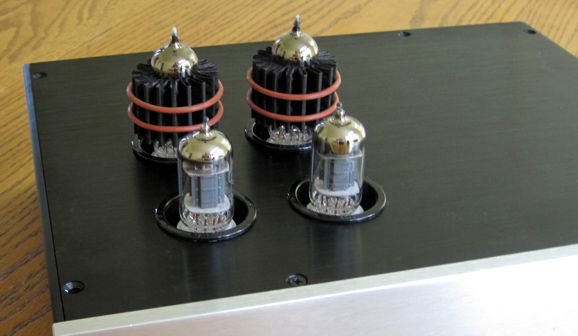
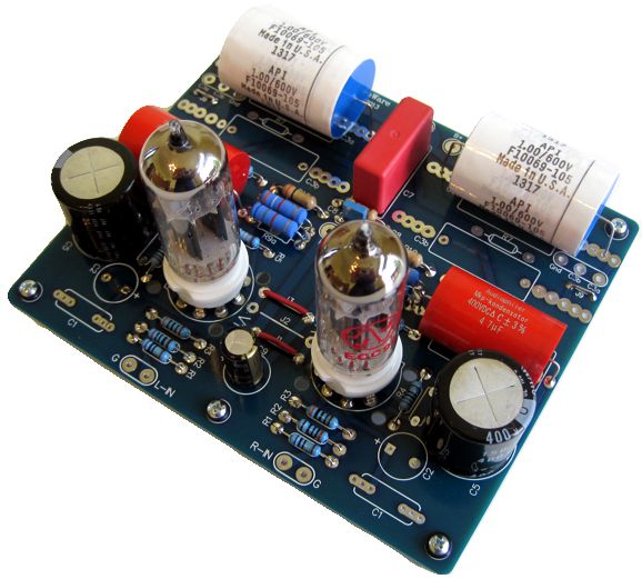
And here is what it looks like with the cover on and tube in place. Yes, that's the new Russian Mullard 12AX7 reissues. No, I haven't listen to them yet, but I hope to do so soon.
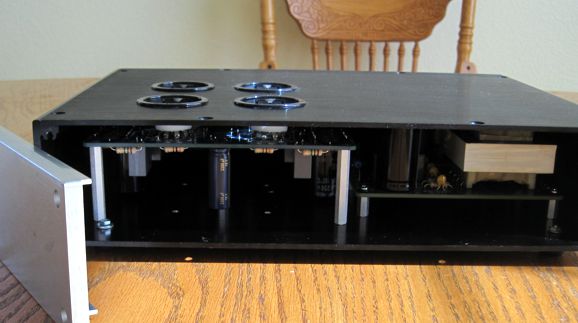
The front panel is super thick and brushed, natural aluminum. I plan seeing if the local machine shop can mill some counter-sunk holes for the knobs. And here is the view from the back.
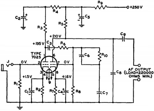
The tube complement is two 12AX7 input tubes and two ECC99 output tubes. I have set up the Tr-PS-2 for 165Vdc output, which is then filtered down to 150Vdc for the tubes. The heaters draw a total of 1.1A @ 12Vdc. Thus, the PS-10, with its much higher B+ voltage and 6.3Vdc heater voltage and 800mA heater output current limit, would never be a good match. What would be a good match? The GlassWare noval ACF and BCF and noval CCDA come immediately to mind, as they only use only two tubes. But if you are the sort of fellow who uses 6CG7 or 6H30 tubes, the PS-10 isn't for you, as their heavy heavy current draw disqualifies them. On the other hand, if you plan on using 6BC8, 6BK7, 6BQ7, 6BS8, or 6DJ8/6922 tubes, you are set with these PCBs. What about , 12AT7, 12AU7, or 12AX7 tubes? They wont work those PCBs, as the boards assume a 12V heater power supply, but they will work other projects. Say you are planning on building a hybrid power amplifier and you need to power the tube frontend's B+ and heater demands, well the PS-10 might be a perfect fit. Here is another example, I know from e-mails that the old RCA's phono preamplifier, from their RCA Receiving Tube Manual, is a big hit with many tube lovers.
Well, this humble circuit, with one 12AX7/7025 per channel is perfect for the PS-10. (*I would add a DC coupled ACF to this phono stage, as most volume potentiometers are between 10k to 100k, not over 220k.) Another possibility is to use one PS-10 per channel, in a dual-mono setup, say with one Aikido mono PCB per channel, each holding two 12AU7 or two 6DJ8 tubes (or what be best: a 12AU7 input tube and a 6DJ8 output), as the PCB allows 6.3V heater arrangements with tubes like the 12AU7.
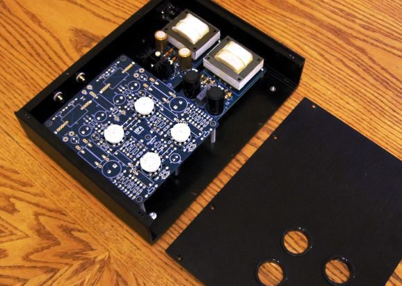
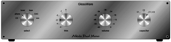
Imagine the same enclosure that I am using for my new headphone amplifier project shown above, which I bought off of eBay from China, filled with a PS-10, an Aikido 9-pin mono PCB, a Select-4 input-selector switch, a M1 66-position stepped attenuator, and a Select-C capacitor switch. Now, imagine this image twice, as each channel would get one.
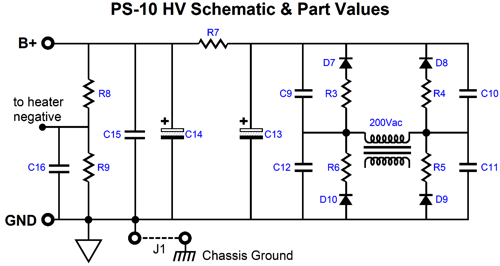
You could select from six signal sources and adjust the volume from 0dB down to -65dB in -1dB steps, while being able to select the best coupling capacitor for any given recording. Nice. Where is the power switch? It could appear on the rear, near the power connector socket; or, a small push-button or toggle switch could be place on the bottom-right corner. Mercy, this would be a relatively easy project to put together. Moreover, it would make many high-end line-stage amplifiers pale in sonic comparison. Behold the twin Davids. Bring on your Goliaths. Two holes would have to be drilled on the top panel, as the 12AU7s are too tall to fit inside the 3-inch tall chassis. I don't mind; in fact, I positively like having them protrude from the enclosure. On the other hand, with proper, full-sized enclosure, say 17 inches wide and 4 inches tall. you could easily house two PS-10 power supply PCBs and two Aikido mono PCBs (dual mono within the same enclosure). The PS-10's 280Vdc raw DC voltage is created by the following circuit.
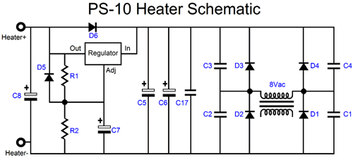
Nothing too fancy, but still filled with small improvements. For example, the ultra-fast rectifiers (HER108) each have a 10-ohm series resistor and a ceramic shunting capacitor, which helps prevent RFI creation. The 280V is then filtered and reduced in voltage by the RC filter made up of R7 and C14 & C15. The heater voltage reference is provided by resistors R8 & R9. Speaking heaters, here is the heater portion of the PS-10:
As can be seen, the power supply’s rectifier configuration is a full-wave bridge that uses ultra-fast MUR410G rectifiers and is powered by the power transformer 8Vac secondary winding. The raw rectified DC is about 9.5Vdc. The low-dropout (LDO) voltage regulator, the LD1085, puts out a fixed 6.3Vdc output voltage. The heater power supply is completely separate from the high-voltage portion. Thus, it can be left floating relative to the high-voltage output or it can referenced to ground or at ¼th the B+ output voltage via resistors R8 & R9. Capacitor C16 AC couples the heater power supply to the high-voltage ground. The power transformer can sustain about 800mA of heater current. A 6922’s heater draws 300mA, so two would draw a total of 600mA, as would two 12AU7 tubes.
The PS-10 uses an EDCOR XPWR083A-120/240 PCB-mount power transformer. Here are its specifications from its data-sheet.
The transformer is quite inexpensive at only $14.94 USD directly from the Edcor web site. In other words, the PS-10 does not come with the transformer. Why not? I would have to wait for them to be made by Edcor, who custom make many of their transformers as needed. (In addition, I would have to pay to have shipped to me.) But at the same time, the rest of the PS-10 kit, which includes all the parts—capacitors, heatsink, regulator mounting kit, LDO regulator, PCB, rectifiers, resistors, standoffs & screws—except the power transformer, costs only $29. Insanely cheap, in other words. Why so cheap? The whole point behind the PCB was that I planned on keeping ten for my own use over the coming years. Now, that I have the Tr-PS-1 and Tr-PS-2, I won't be needing them (other than the one I already assembled and that I plan on keeping for an emergency); and I know that for many tube lovers such an All-in-One tube power-supply kit would be a godsend. So, I am letting go of nine PS-10 kits, as I am sure someone else needs them. By the way, I don't plan on making anymore after that—unless, of course, my arm gets twisted enough, which does happen every once in a while. Sadly, the PS-10 kit is no longer available.
More on the SRPP Topology Confucius famously said, “Life is really simple, but we insist on making it complicated.” But with regards to the SRPP circuit, most tube lovers go in the other direction, making something complex overly simple. They imagine that the SRPP is just magic, something like a universal solvent, an electronic universal solvent which can dissolve all electronic problems, as if by magic. Seemingly, no electronic use is exempt. Need to drive electrostatic speakers, use an SRPP. Need to amplify an MC phono cartridge's miniscule output signal, use an SRPP. Need to drive a cathode follower's grid, use an SRPP circuit. Need to design a TV, clock radio, remote control, electric toothbrush, microwave oven... use an SRPP circuit. Alas, if only life were that simple. The reality is that the SRPP does not work well in many applications, but it does work well in one very limited use; namely, the delivering of push-pull power into a resistive load, not just voltage and not into a reactive load, such as a capacitor or inductor. Moreover, can never be truly universal, even within the same application, such as a headphone amplifier, as the SRPP's internal current-sense resistor, the one that falls between the bottom triode's plate and the top triode's cathode, must be selected to match both the top triode used and the load resistance driven. In other words, an SRPP headphone amplifier that was designed to work well with a 300-ohm load, will not perform well with a 32-ohm load; and vice versa. It appears that the SRPP circuit is not the all-encompassing electronic-problem solver after all. Indeed, if the goal is not delivering power, then the SRPP is probably not the right choice. In my last post, I showed a witty design that inverted the order within an SRPP hybrid power amplifier, as the input stage was not an SRPP; the output stage was. Surprisingly enough, this circuit provoked much interest, and the e-mails followed. Thus, we should down-shift a few gears and go over the circuit in greater detail.
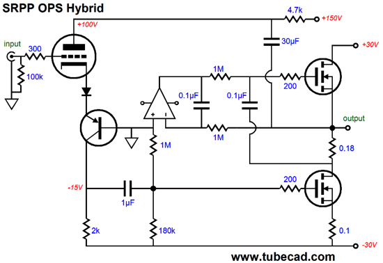
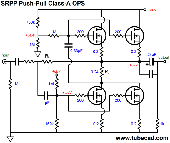
The triode's varying current conduction, the result of an input signal, travels through the PNP transistor down through the 2k load resistor, which develops the input signal for the bottom MOSFET. This MOSFET then varies its current conduction in response and this varying current flows through the 0.18-ohm sense resistor, creating the needed input signal—an inverted input signal—for the top MOSFET, resulting in true push-pull operation, with the top and bottom MOSFETs conducting in anti-phase,each giving up as much current as the other takes up, then giving up as much as the other summons. The speaker sees the delta, the difference, in current conduction between top and bottom MOSFETs as its current signal. Surely, I mean output voltage, not output current? No, I mean current. Interestingly enough, the output impedance with MOSFET, which do not present anything like the plate resistance of the triode, exhibit an output impedance so high that it is best to treat the output stage as a current-out amplifier, or a voltage-to-current converter. (With a global feedback loop in place, the output impedance can be reduced to a low value.) For this bit of magic to work requires that we never leave strict class-A operation, as the top MOSFET can only get its input signal if the bottom MOSFET is not completely shut off. No current, no signal. Our goal then is to set the idle current to a sufficiently high value that the bottom MOSFET never cuts off. How much current is that then? It depends—the most hated answer of all. What is the load impedance and how much power do you plan on making available to it? In the above example, with ±30V power-supply rails, the actual peak output voltage would be about 24V, which into an 8-ohm load equals 36W, as W = V²/(2· Rload). If the load had been 4 ohms, the wattage would equal 72W. With a class-A, push-pull output stage, the idle current must at least equal half of the peak current output; thus, we must find the peak output current first. This is simple enough, as Ipk = Vpk/R. So, in this example, with an 8-ohm load, the peak current flow is equal to 24V/8 or 3A. Thus, the idle current must at least equal 1.5A. The big problem here is that this is a lot of current, even for a big 150W power MOSFET. For example, 1.5A against the 60V of power-supply voltage equals 90W of heat at idle, which is plenty hot.
My own thermal limit is 60C for heatsinks (hot enough to make you instantly retract your probing fingers and not so hot that you leave brunt skin behind) and assuming that the silicon junction is still comfortably below its rated limit. Well, first subtract the air temperature, 25C from the goal of 60C, getting 35C, which we then divide by 90W and you get the needed thermal resistance (0.39C/W) of the heatsink per channel; this means that for every watt of heat generated by the output devices, the heatsink will see a 0.39C rise in temperature. This is a fairly low amount of resistance, which implies a big and massive heatsink. Admittedly, big heatsinks are readily available, although not cheap. The next problem is the danger of overheating the MOSFETs. If you do the math, you find that with 90W of heat and a 0.39C/W heatsink and MOSFET junction-to-case thermal resistance of about 0.8C/W and an insulator and grease (about 1C/W) and an ambient temperature of 25C, the MOSFET junction temperature will be 141C, way too hot for its 150C limit. The workarounds are bigger heatsinks (or water-cooled heatsinks) and/or more MOSFETs in parallel—or fewer watts of output power, and thus lower rail voltages and idle currents. Well, we could try doubling up on the MOSFETs. For example, with four power MOSFETs, the junction temperature drops to a comfortable 101C.
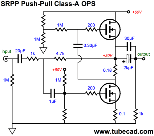
In the above schematic, we see four output MOSFETs, each idling at one quarter of the peak current flow into the speaker, in other words, 0.75A. The same 90W of heat is generated at idle, but the junction temperatures are only 101C, with the same heatsink and ambient temperature. I think this is still bit too hot, as hot days and cat fur and dust increase the heat the MOSFET withstand, so I would use bigger heatsinks and Kapton insulators (well, at least until thin film polycrystalline diamond insulators are available at Mousers). Or, bite the bullet, and go for six MOSFETs per channel. It's not the added expense that bothers me, as they are relatively cheap; no, it's the higher capacitance that each additional MOSFET adds, about 1,300pF per pair of MOSFETs added. Assuming that we have sufficiently cooled the MOSFETs, we can move on the the current-sense resistor, whose value in the above circuit has changed from its previous value. Why? I added 0.2-ohm source resistors to the top MOSFETs (so as to prevent current hogging) and the lower idle current resulted in a drop in the MOSFETs' effective transconductance (gm), so a new value was needed. How do we find the value. We start with math. The resistor's value should, with MOSFETs and transistors, roughly equal the inverse of the gm. Rs = 1/gm Fantastically simple, no? Unlike triode-based SRPP circuits, the MOSFET doesn't care what the load resistance is, be it 4 ohms or 8 ohms or even 0.8 ohms. Well, actually the load does make a small difference, but not much of one with a high-gm MOSFET. For example, with a load of zero ohms, yes 0-ohms, the optimal Rs resistor value is 0.18; but with a 16-ohm load the optimal value increases to 0.19, a 0.01-ohm difference, a rounding error or the same error a 5% resistor could add, in other words. But the top MOSFET does care about getting its gm right. With a source resistor, which both linearizes the MOSFET and prevents current hogging and thermal runaway, the gm drops. By how much? Here is the formula: gm' = gm / (1 + gm·Rs) Thus, the current-sense resistor must now equal Rs = 1/gm' My quick guesstimate was that 0.2 ohms would be needed. Well, I ran some SPICE simulations and found that 0.24 ohms was the right value for the four IRFP240 MOSFETs at that 0.75A idle current. Why the difference? At half the idle current per device, the transconductance fell a bit, so a slightly bigger sense resistor was needed. By the way, when SPICE was created, a great deal of effort went into getting the MOSFET models to work well (within the SPICE source code, MOSFETs get their own program class, vacuum tubes don't), so I am about ten times more confident of the simulation results with MOSFET than I am with triode simulations.
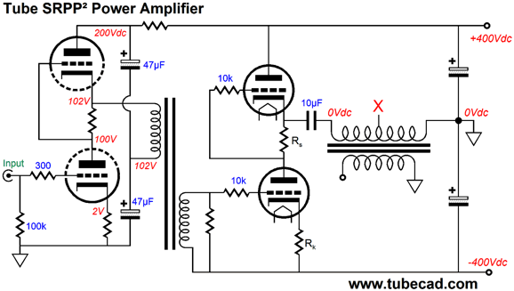
SRPP² Hybrid Amplifier
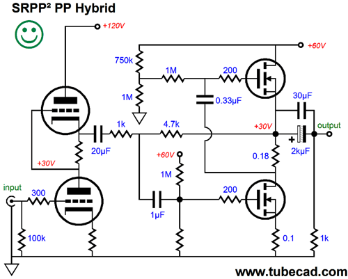
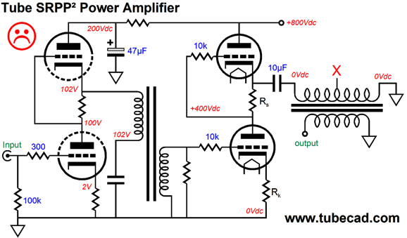
In the above schematic, we see a triode-based SRPP circuit driving the MOSFET-based SRPP output stage. This is not a gratuitous SRPP design, as the input SRPP stage actually has a low-impedance load to drive, the 1k feedback resistor. We must use a low-value resistor here, as the MOSFET present a very high input capacitance. (This explains what the famous Nelson Pass Zen amplifier also use low-valued feedback resistors.) The triode was not specified, but a 6DJ8 is what I had in mind. The smiley face is there to show that this is the preferred way to approach an SRPP², with a mono-polar power supply and capacitor coupling to the speaker. The wrong way to go is the following design.
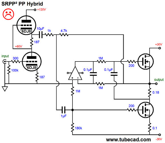
Are you sure, John, as it look awesome? Hell, I am going to build it anyway. Of course, you are free to do as you please, but the design holds a severe design problem, which interestingly enough, would never show up in SPICE simulations—unless, of course, that you knew enough to go looking for it. The problem is that the negative power-supply rail will hold some ripple, with a 1.5 to 3A current draw expect plenty, which the SRPP input stage cannot be easily made to take into account, so this ripple will be treated as an input signal by the bottom MOSFET. No good. Note how this problem does not obtain with the previous version, as the bottom MOSFET, the one that produces gain, has its source connecting to ground, not a noisy power-supply rail. (One possible workaround would be to use P-channel MOSFETs instead, delivering the input signal to the top MOSFET, which would at least put the ripple from the tube B+ and the +30V rail in phase, which would help. If they were both in phase and equal in amplitude, then the noise would null, falling out of the equation.) Once again, just because we have a winning topology, does not mean that it will be easy to actually build it. For example, the same class-A heat build-up is present, so the same heat-avoiding tactics are required as before: big heatsinks and more MOSFETs—possibly lower rail voltages.
SRPP Tube Output Stage
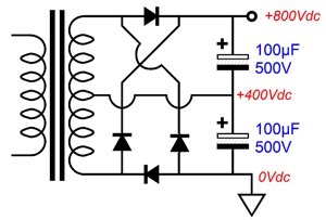
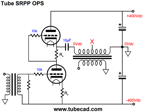
Although the power-supply capacitors are lower in value, this power supply still packs a wallop, as +800Vdc is scary high. (I hate working with such high voltages, as I can feel my arm hairs being pulled by the electrostatic charge. And God forbid that I ever sneeze inside an energized amplifier.) One workaround is to keep the present high-voltage power supply but place the ground at the midpoint, creating a bipolar power supply, whose ±400V rails are 1/4th as dangerous as the 800V one, as the wallop increases by the square of the voltage.
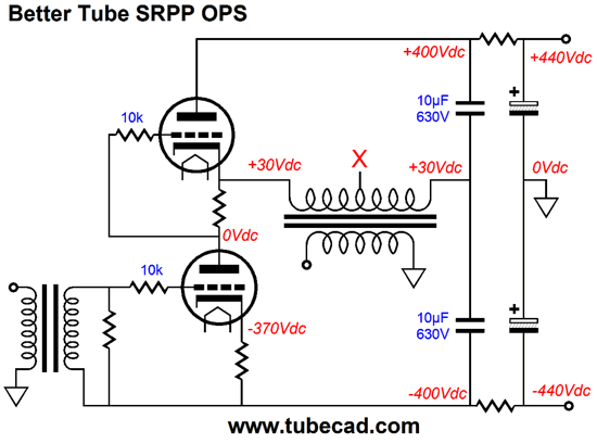
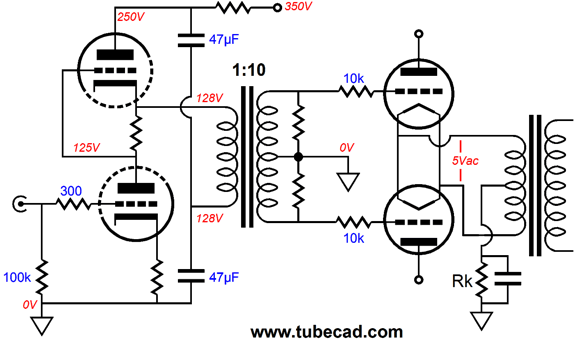
Don't we run into the problem of the negative power-supply rail's ripple causing signal problems, just as we had with the MOSFET SRPP and the bipolar power supply? Not necessarily, as we can use a signal transformer to shield us from the ripple, as shown above. The negative power-supply rail can roar with ripple, but the inter-stage transformer is indifferent to it. In addition, note how both the two tubes and the power-supply rails split the positive and negative rail ripple, creating a null at both midpoints. Wonderful, as the power-supply noise drops out of the equation. Heck, we can use an SRPP input stage to drive the signal transformer, particularly if the load resistor is low in value on the secondary and/or the winding ratio steps up the signal voltage.
The input stage non-gratuitously uses an SRPP stage, as it does have a low-impedance load to drive. For example, lets say that the inter-stage transformer offers a step-up ratio of 1:4, which implies an impedance ratio of 4² (or 1:16). Let's also say that the transformer works best when the secondary is terminated by 4,800 ohms. Well, with the impedance ratio of 1:16, the SRPP sees a load impedance of just 300 ohms, plenty low. Indeed, probably too low. As an idle current of 10mA would only garner voltage swings of up t0 6Vpk into 300 ohms, which the inter-stage transformer would step up to 24Vpk, not enough to drive the bottom output triode to full output. If we keep the same impedance ratio, however, we should terminate the inter-stage transformer with a 12k load resistor, if we can get away with it, as it would reflect back to the input SRPP stage as 750 ohms. Now, twice the 10mA idle current into 750 ohms equals peak voltage swings of 15V, which the inter-stage transformer would step up to peaks of 60V at the output tube's grid, which would probably be more than enough. The more I think about, the less confident that I become that a single input tube would suffice. why not? Well, with a 6DJ8/6922 input tube, only a gain of about 4 would be realized with the 750-ohm load, so an input signal of a tad less than 4Vpk would be needed. Sure, most tube line stage can easily produce this big an output voltage swing, but the standard is 1Vpk for full output from a power amplifier.
Speaking as a man known for his stingy approval of the SRPP topology, I have to say that I love the circuit shown above. First of all, who else but me would design such an amplifier? I positively drips with Broskie flair and panache. Second, it cleverly, if I say so myself—which indeed I do—sidesteps the SRPP's poor PSRR of -6dB by terminating both the inter-stage and output transformers with a the same power-supply-noise division of 50%, thereby greatly improving the PSRR at the output. Remember that a transformer's winding is intrinsically a differential device, which can only see deltas in current and voltage; where there is no delta, there is no output signal. Wait a minute John, before you sprain you arm from patting yourself on the back excessively, the output transformer terminates into ground, which by definition is noise free. True enough, but relative to the bottom triode's cathode, the ground seems to present 50% of the power-supply noise present from negative rail to positive rail; and relative to the top triode's plate, the ground also seems to present 50% of the rail-to-rail power-supply noise. Electronic relativity, you gotta love it. Remember that the two rails hold equal, but out of phase noise signals. Now, if the SRPP didn't halve the power-supply noise that spans from +400V to -400V, say it quartered it, then the connection to noise free ground would prove noisy. Here is a simple example, say we shunt the bottom output tube's cathode resistor with a big capacitor, so we can get more gain. We will get more gain, but we will also get more noise, as the SRPP output stage will no longer split the rail-to-rail noise, with maybe only a quarter or third of the noise being present at the SRPP's output. To highlight the design's PSRR enhancements, let's look at the same design, but as it would be designed by your average tube guru.
Both the inter-stage and output transformers go to ground and the noise at the output skyrockets. Why? In the input stage, 50% of whatever power-supply noise is present at the top triode's plate gets fed into the inter-stage transformer, which the output tube treats as signal and amplifies; and 50% of whatever power-supply noise is present at the 800V B+ connection gets fed into the output transformer—all of which gets fed to the speaker and, ultimately, you ears. Are you sure, John, as it look awesome? Hell, I am going to build it anyway. And people wonder why I drink. Bear in mind that, in all these designs, the top tube will require its own floating heater winding (or DC power supply) referenced not to ground, but the top tube's cathode; additionally, this power source cannot be shared between channels, as each top tube will swing huge voltage extremes. The bottom tubes, in contrast, can share a common heat power supply and it will be referenced to the negative power-supply rail. Note the coupling capacitor that connects the SRPP's output to the output transformer. It's value is surprisingly low, don't you think? The formula is an easy one: C = 159155/F/R, where C is the capacitance in µF and F is the lowest frequency and R is the primary impedance. A different approach would be to to forgo the use of the coupling capacitor.
The two 10µF capacitors serve to two purposes here: the first is as coupling capacitors, which prevent DC current from flowing through the primary, which could cause core saturation, particularly with toroids; and, second, they serve as ripple filters with the two series resistors. By the way, we can use this configuration with a more typical push-pull output stage, for example:
Just how much power might such an amplifier put out. Well, it depends. But let us start with the crazy assumption that the full 400V appears across the primary, whose impedance is 4300 ohms. in this extreme case, 400V²/(2 x 4300) = 18.6W average watts or 37.2W of fake peak, high-end-audio watts. Why so little? The quick answer is the high primary impedance, which in a class-A push-pull amplifier remains high, unlike a class-B push-pull amplifier, wherein the 4300 ohms would quarter to only 1075 ohms. One workaround is to mis-tap the secondary. Instead of attaching our 8-ohm speaker to the 8-ohm output tap, we use the 16-ohm tap, which will reflect only 2150 ohm on the primary. Does that make a difference? Oh yes, as 400V²/(2 x 2150) = 37.2W real watts. The reality is that we could never get the full 400V to appear across the primary, as the cathode resistor and the triode's plate resistance limit the available voltage. By how much. It depends. Here is a useful formula to find the peak current flow into the primary: Ipk = B+/(Rk + rp + Rload) where rp is the plate resistance. Lets assume a cathode resistor of 200 ohms and an rp of 800 ohms. Once we plug these values into the formula, Ipk = 400/(200 + 800 + 2150), we get 127mA of peak current, which we then plug into the following formula to get the power output. W = Ipk² x Rload/2 In this example, we get W = 0.127² x 2150/2, or 17.3W, which is not bad for a class-A power amplifier. By the way, since we know the peak current, we also know the idle current, 63.5mA. This idle current against the 800V of total power-supply voltage equals 50.8W of heat at idle, with the triodes splitting the remainder after the subtraction of the two 200-ohm resistors 0.8W of heat each. Math, you gotta love it.
No-Signal Transformer SRPP Amplifier The following design uses no inter-stage (or signal) transformer within the amplifier; in its stead, a Bastode circuit or "inverted cascode" circuit relays the ground-referenced input signal down to the bottom output tube, with both gain and no phase inversion.
The Bastode circuit is not just a ground-cathode amplifier stood on its head, as it, like its cascode cousin, can deliver a signal gain in excess of the triode's amplification factor (its mu). For example, in the above circuit, with a 6SN7 or 6J5 triode, the gain from the input stage comes in at about 26, which is more than the triode's mu of 20 would allow in a grounded-cathode amplifier. One problem we face is finding a sufficiently robust PNP transistor. As far as I know, -400V is the maximum emitter-to-collector voltage available. Several workarounds present themselves. First, we could shunt the PNP transistor with a 200V zener, so the device would be protected from over-voltages. Or, we might find a P-channel MOSFET with a higher breakdown voltage, say 600V or 800V. Or, we could lower the power-supply rail voltage to something less, say ±300V. Or, we could use two PNP transistors in series.
Note how the two MJE5852G PNP, high-voltage transistors split the -400V power-supply rail, each getting -200V. Well, that is true at startup, when the triode above is still cold and not conducting, which is precisely when I worry most. Why? One reason is that at startup, the power-supply rail voltages can develop very quickly and will be substantially higher than their normal in-use voltage. Why? High-voltage power transformers hold high DCR (DC resistance) on their secondaries, which create a large DC drop when under heavy load current; but when unloaded, there is no large DC drop, so the nominally ±400Vdc rail voltage can exceed ±500Vdc. This also helps explain why I used two 0.1µF capacitors shunting the two-resistor voltage divider resistors, rather than a single capacitor to ground. In other words, at startup, when the negative power-supply rail voltage is something like -500V and the two capacitor in place, the bottom PNP transistor won't see the full -500V, as the two capacitors will charge equally, splitting the negative power-supply rail voltage along the way. But once the amplifier is hot, the bottom PNP transistor sees only -100V across it, as the 20k load resistor will drop 100V. Since we can get a lot of gain from the input stage, we can employ a negative-feedback loop. We can extend the feedback loop across the output transformer, attaching at the secondary, as shown below.
Or, we can attach the NFB loop to the primary.
Because the signal is inverted at the connection to the primary, we must employ the inverting feedback style NFB loop, which attaches to the input triode's grid, not its cathode. As the input frequencies fall below the cutoff frequency imposed by capacitor C1, the negative feedback will turn off, causing the gain to rise. We can counter this unintended bass-boost by carefully choosing capacitor C2's value, which can create a countering low-frequency cutoff. Why would we need a negative feedback loop? Isn't the SRPP a type of cathode follower? The two output triodes plate resistance save the day, as the two are effectively in parallel, which gives the primary some impedance to grab onto. Had pentodes been used in the triode's stead, the output impedance would so high that that the amplifier would effectively become a current-out type. This may be a good thing, but it may also come as a surprise, if you expected to encounter some dampening factor. The NFB loop creates that dampening factor, by substantially reducing the output impedance.
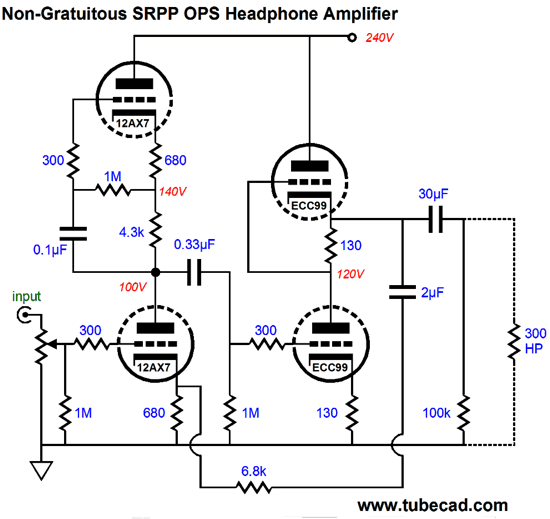
SRPP² Headphone Amplifiers
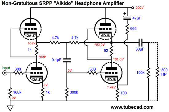
The 12AU7 drives the 4.7k feedback resistor and the 6DJ8 drives the 300-ohm headphones. I added the sneaky/signature noise-canceling circuit of the 665-ohm resistor and 47µF capacitor to cancel the power-supply noise at the output. Well, this got me thinking: couldn't I do the same with a grounded-cathode amplifier as the input stage. Here is what I came up with:
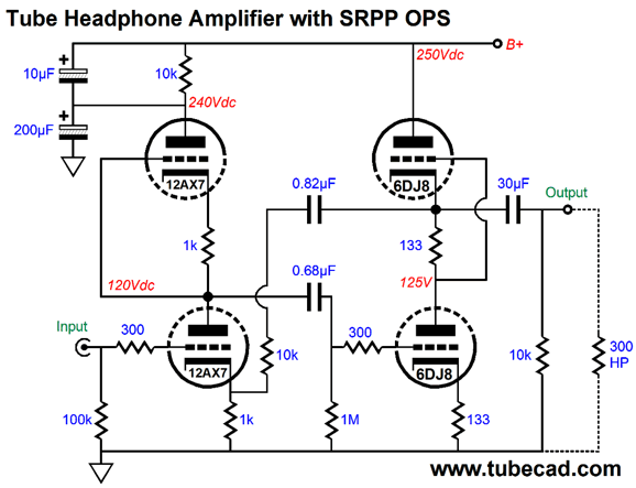
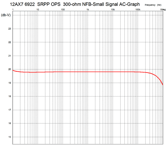
The 12AX7-based input stage delivers a gain of 50 (+34dB) and the 6DJ8-based SRPP output stage develops a little voltage gain as well. The 10k feedback resistor sets a final gain of about 10 (+20dB) and lowers the distortion and output impedance. All fairly obvious. What isn't obvious is what the two capacitors at the top left of the schematic are doing. Why is the 10µF capacitor there at all? It is there to purposely leak a small amount, 1/20th, of the power-supply noise into the the top 12AX7 plate, half of which will leak out at the bottom 12AX7 plate. The result is that this trickle of noise gets inverted and amplified, thereby nulling with the power-supply noise already at the output. Sweet. Once again, can you imagine anyone else using the two-capacitor noise null? An additional bit of magic is the the optimal coupling-capacitor values. Didn't it seem odd that 0.82µF and 0.68µF capacitors are specified? Why not make them the same value or different values? The answer is that with these values a truly interesting result obtains: flat low-frequency output.
The graph starts at 1Hz and ends at 1MHz. By fiddling with these two capacitor values we can create bass boosts or dips or, what we have here, a fairly flat low-frequency response. As I said, truly interesting. What is going on is that the low frequencies are actually rising, but at the rate as the 30µF coupling capacitor to the 300-ohm headphones is cutting them, so they effectively cancel each other out. By the way, be sure to compare this SRPP headphone amplifier to the one I presented in blog number 293:
It, too, offers a good PSRR, but does so through more of a brute force way. Here the top 12AX7 triode functions as a quasi constant-current source, which both helps the bottom 12AX7 triode develop more gain and leak less B+ noise. I would love to hear a shootout between the two designs.
A Wedding in Heaven?
The PS-10's limited heater current of 800mA is easily enough for two 6DJ8s and the 20mA current limit is also enough for most SRPP designs.
//JRB
Next Time
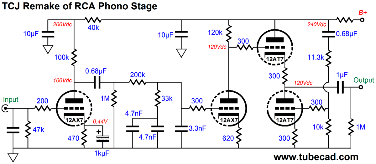
*TCJ Remake of RCA Phono Stage
This tube phono preamp is flat from 20Hz to 20kHz within 0.1dB and the 12AT7-based Aikido cathode follower (ACF) stage greatly improves the PSRR and offers a low output impedance. The only difficult part of designing this phono stage was making sure that readily available RIAA EQ capacitors were used, which s why two 4.7nF capacitors were placed in parallel. The gain comes in at a little over 47dB. Unfortunately, the PS-10 can not power its heater demands, as the four tubes will draw 1.2A at 6.3Vdc. The PS-3 or PS14 or Janus Regulator on the other hand...
User Guides for GlassWare Software
For those of you who still have old computers running Windows XP (32-bit) or any other Windows 32-bit OS, I have setup the download availability of my old old standards: Tube CAD, SE Amp CAD, and Audio Gadgets. The downloads are at the GlassWare-Yahoo store and the price is only $9.95 for each program. http://glass-ware.stores.yahoo.net/adsoffromgla.html So many have asked that I had to do it. WARNING: THESE THREE PROGRAMS WILL NOT RUN UNDER VISTA 64-Bit or WINDOWS 7 & 8 or any other 64-bit OS. I do plan on remaking all of these programs into 64-bit versions, but it will be a huge ordeal, as programming requires vast chunks of noise-free time, something very rare with children running about. Ideally, I would love to come out with versions that run on iPads and Android-OS tablets.
//JRB |
I know that some readers wish to avoid Patreon, so here is a PayPal button instead. Thanks. John Broskie
Kit User Guide PDFs
And
High-quality, double-sided, extra thick, 2-oz traces, plated-through holes, dual sets of resistor pads and pads for two coupling capacitors. Stereo and mono, octal and 9-pin printed circuit boards available.
Designed by John Broskie & Made in USA Aikido PCBs for as little as $24 http://glass-ware.stores.yahoo.net/
The Tube CAD Journal's first companion program, TCJ Filter Design lets you design a filter or crossover (passive, OpAmp or tube) without having to check out thick textbooks from the library and without having to breakout the scientific calculator. This program's goal is to provide a quick and easy display not only of the frequency response, but also of the resistor and capacitor values for a passive and active filters and crossovers. TCJ Filter Design is easy to use, but not lightweight, holding over 60 different filter topologies and up to four filter alignments: While the program's main concern is active filters, solid-state and tube, it also does passive filters. In fact, it can be used to calculate passive crossovers for use with speakers by entering 8 ohms as the terminating resistance. Click on the image below to see the full screen capture.
Tube crossovers are a major part of this program; both buffered and un-buffered tube based filters along with mono-polar and bipolar power supply topologies are covered. Available on a CD-ROM and a downloadable version (4 Megabytes). Download or CD ROM For more information...
To purchase , please visit our Yahoo Store:
|
|||


| www.tubecad.com Copyright © 1999-2014 GlassWare All Rights Reserved |