| John Broskie's Guide to Tube Circuit Analysis & Design |
|
26 February 2018 Post 414
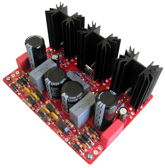
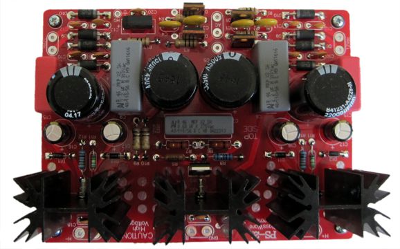
New Power-Supply Kit for Tube Equipment: PS-21 The high-voltage regulator holds the same circuit as the PS-1 and the two low-voltage regulators are similar to the H-PS-1 circuit, but differ in that the rectifier circuit cannot be configured as a voltage doubler.
The assumption is that the two low-voltage regulators will be set up to deliver 12V or 12.6V, although they can be configured for 6.3Vdc output. Many, many audiophiles insist on 6.3Vdc, as they cannot imagine placing two 6.3V heater elements in series—apparently the universe simply isn't that rich and compliant. But a very good argument can be made for running a 12Vdc output voltage, in spite of the mental anguish it might provoke in the only-6.3V groupies, as it effectively doubles the amount of current the regulator can pass and it gives the regulator more voltage headroom. In general, low-voltage regulation is a pain with linear regulators, due to rectifier losses and regulator headroom requirements, which is why switcher power supplies are so popular and ubiquitous, as they do not waste half the potential power in the power supply itself. Amazingly enough, I was able to fit the three regulated power supplies on a PCB 4.5in by 6in big (or, rather, small), the same size as the PS-1 PCB. I needed this new power supply PCB, as I have also designed new Aikido PCBs to test the value of independent heater power supplies. Of course, the PS-21 could be used with other circuits. For example, often we are limited in our designs by the relatively low heater-to-cathode voltage limit (usually 100V), so we cannot use as high a B+ voltage as we might like or design multitier efforts, with some tubes situated high above ground potential, while others sit far down at a negative power-supply rail voltage, with far too much voltage between top and bottom cathodes to allow a single heater power supply to be used. (One day, I will build a 400V Aikido line-stage amplifier with eight 6J5 single-triode tubes, four per channel, with four low-voltage heater regulators, two per channel, one referenced to 80V, while the other is referenced to 280V.) Still another possibility is to make a bipolar, low-voltage power supply out of the two low-voltage regulators. Think tube-hybrid headphone amp, with tubes driving solid-state devices; or a hybrid phono stage, with low-noise OpAmp driving a tube circuit. The last possibility that I will mention, although I can easily think of scores of possible applications, is that the second low-voltage regulator can power a stand-alone DAC. Some DACs require 12Vdc, others 9Vdc or 5Vdc. A good linear regulated power supply can make a huge improvement in sound over the cheesy switcher wallwart that came with the unit. In other words, we build a tube-based buffer or line amplifier and power the DAC from the same power supply PCB that powers the tubes. Nice. The PS-21 kit is available now at the GlassWare Yahoo Store.
More Cathode-Coupled Amplifiers Indeed, that is an interesting question. When I was a teenager, I was told repeatedly that I should become a lawyer. Then after college, I was told that I should become an opinion columnist. No doubt, half of the time, I received sincere career-guidance consultations; the other half, thinly veiled insults. I had far too much respect for the law to become a lawyer, whose job after all is to circumvent the law. And talking-head opinion spewers drove me crazy—not due to my disagreeing with them, which I usually did, but due to their relentless and plodding repetition. The weeks and months and years progressed, but the same old columns appeared over and over. And to what end, as those who agreed, still agreed; those who didn't agree, still didn't agree. It was for such an endeavor that the word "Sisyphean" was coined. Relentless repetition was not the exclusive domain of opinion writers, however, as I could go a year or two before I read something truly novel in the audio press. Now that I have almost achieved maturity, being one fourth as old as The United States, I can see that my expectations were in fact too high. Just as Playboy magazine wasn't bought for its articles, Audio, High Fidelity, and Stereo Review magazines were not bought for their articles either. Why were they bought then? Possibly, primarily for the items I liked least: the ads. And just as Playboy must have published a few good articles, although the prevailing wisdom was that writers always sent their worst stuff to the one-hand press in spite of it paying the most, the glossy HiFi magazines did publish some good articles, including some great articles. For example, Audio magazine actually printed DIY articles by such greats as Nelson Pass and High Fidelity routinely ran wonderful music articles; sorry, I cannot think of anything good to say about Stereo Review. I lie. I forgot about the fabulous Charles Rodrigues cartoons. My favorite being the customer in a high-end audio store being handed a remote control with tubes protruding from it and he says, "This whole tube revival thing is getting out of hand." A genius. For his cartoons alone, the subscription was worth it. The word "journalism" comes from the word "journal," which in turn meant a daily publication, with the first journals being books of daily prayers. The keyword was "daily." We should expect a very poor signal-to-noise ratio with anything that recurs daily. With weekly efforts, we can expect more, but not that much more. Bill Bryson, the wonderful Bill Bryson who was born in Des Moines, Iowa, but lived most of his life in England, recounted in his book, I am a Stranger Here Myself, a commencement speech which he ended with the reflection,
Bill is right. Repetition might be the death of art, but it is the life of learning. The secret is in getting the right ratio between repetition and the new.
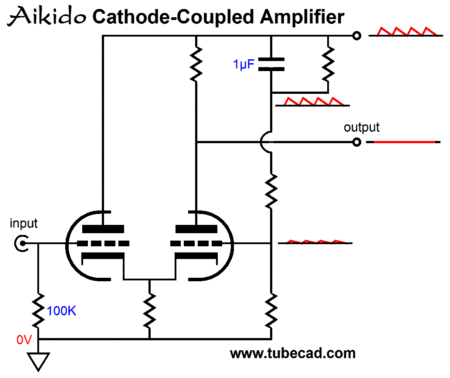
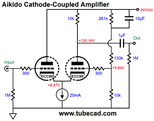
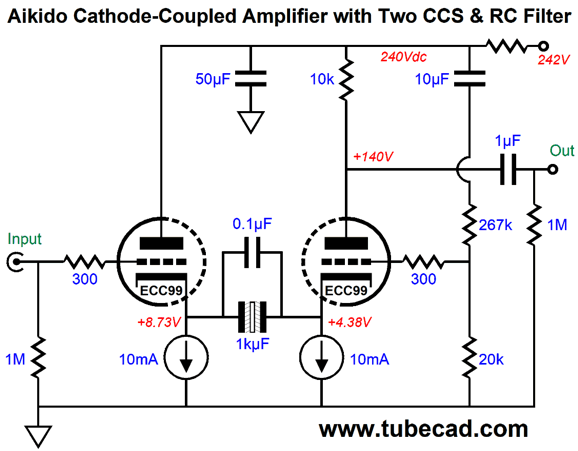
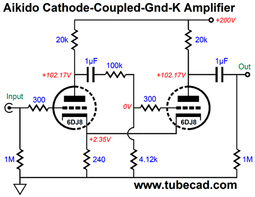
Aikido Cathode-coupled amplifier
The problem of dissimilar cathode-to-grid voltages between triodes is solved by feeding the right triode a slightly higher DC grid voltage. Ideally, we want both triodes to idle at the same current, as this ensures the best performance; but the right triode sees a much lower cathode-to-plate voltage than the left triode sees, so the same cathode-to-grid voltage cannot be shared between triodes. In addition, the three-resistor voltage divider allows us to inject a sampling of the power-supply noise into the right triode's grid, which will modulate its current conduction to produce an anti-phase response to the B+ ripple and, no less important, to the audio-signal-induced power-supply perturbations.
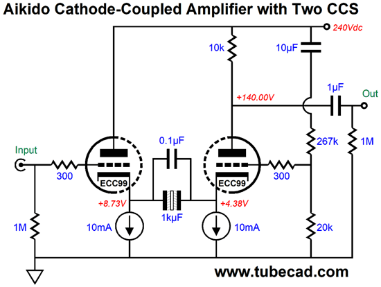
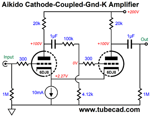
The constant-current source auto bias the two triodes and greatly improves the cathode-coupled amplifier's performance. Nonetheless, it could be replaced by a resistor, preferably a long-tail resistor, i.e. a large-valued resistor that terminates into a substantial negative-power-supply voltage rail. With a cathode resistor in place rather than a constant-current source, the amount of power-supply noise needed to null the noise at the output will need to be adjusted. The tube shown above is the JJ ECC99, which I have grown quite fond of, as it sounds good and is easily available. Its downside is that its heater draws 400mA at 12.6V, whereas a 12AU7 only draws 150mA at 12.6V. Of course, a different tube could be used, such as the 6BL7, 6H30, Russian and Chinese 6N6 noval tubes, 12BH7, 5687. The 6DJ8 and 6SN7 could be used if a negative power-supply rail, which could be just -6.3Vdc, were used, which would allow the constant-current source more voltage headroom. Returning to the constant-current source, the usual suspect, the LM334, tops out at about 10mA. To get to 20mA, we could use two in parallel or more. Another solution might be to give each triode its own constant-current source, which would truly auto-bias each triode. How would we couple the triode cathodes then? Easy enough, if you can tolerate a large-valued coupling capacitor. How large a capacitor? At the very least, 10µF, but bigger would prove better, say 100µF to 1kµF. Such a large value moves us out of the land of film and PIO into the land of the polarized electrolytic capacitor. Or does it? A third land exists, the land of non-polarized electrolytic capacitors. These non-polar capacitors hold two polarized electrolytic capacitors in opposition and, for reason not entirely understood, sound much better. Very expensive and very fancy loudspeakers hold non-polarized electrolytic capacitors in their crossovers. This type of capacitor's downside is that they are twice as large as comparable polarized electrolytic capacitor and they are only made with voltage limits of up to 100V. Of course, with cathode voltages less than 10V, this voltage limit is not a concern.
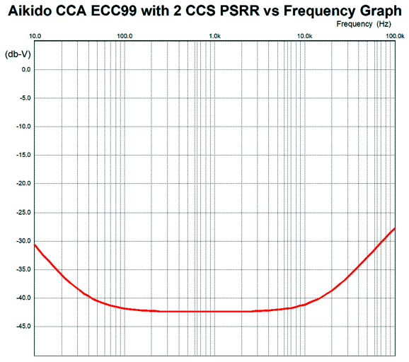
Note how both grids now see the same 0V ground potential, which is the result of losing one voltage divider resistor. The Aikido mojo still obtains, but we can far more easily adjust voltage divider resistor values, as a change in values only results in a change in AC signal voltage division, not DC voltage division. Indeed, we could even add a potentiometer to the mix, so we could dial in the deepest power-supply noise null at the output. (In general, I am loathe to allow a steady flow of DC current through a potentiometer, but in this setup, no DC current flows through the wiper.) Such an arrangement would allows us to perform some easy tube rolling, as the ECC99 could be replaced by a 12BH7. If the 1kµF and 10µF capacitor values seem too egregiously large, be assured they aren't. Here is the SPICE-generated PSRR versus frequency graph with the above values.
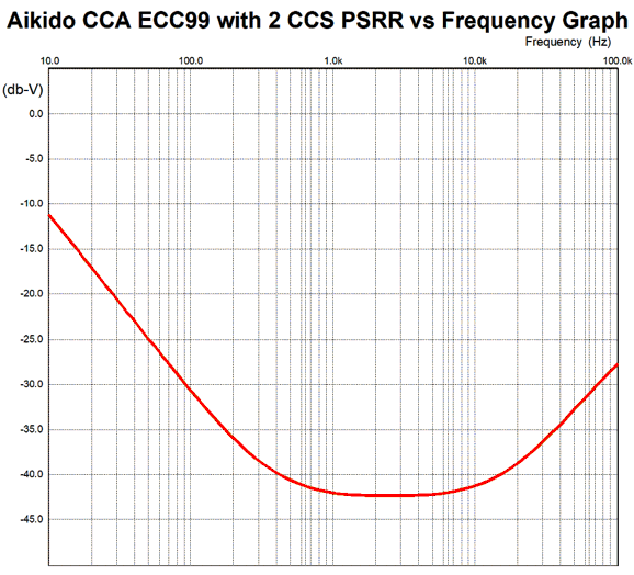
Now, here is the graph with 100µF and 1µF capacitors.
Ideally, we want to see a flat line at -100dB. Failing that, we must pay attention to 120Hz here in The States and 100Hz in Europe, as that is where we will find the most power-supply ripple. The bigger capacitor values moved the null into lower frequencies. By the way, we shouldn't worry too much about the frequencies above 10kHz, as the shunting capacitors from the B+ voltage to ground should prove supremely effective above 10kHz, as a 50µF capacitor presents an impedance of 0.318 ohms at 10kHz. Here is an example; note the added RC filter to the B+ connection. (100-ohm resistor in the RC filter, by the way.)
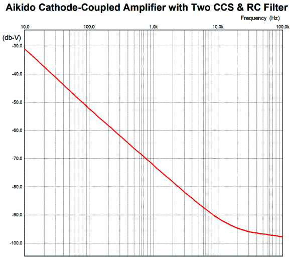
Now, let's look at the PSRR versus frequency graph.
This does not reveal the actual amount of noise exiting the Aikido cathode-coupled amplifier, but the relative attenuation of whatever power-supply noise happens to be present on the B+ connection. In other words, this graph only represents the final amount of noise, if the amount of ripple equals 1V. If the amount of noise is only 1mV, quite likely, then the entire plot line must be moved down by -60dB. (Of course, resistor and tube noise will prove much higher.)
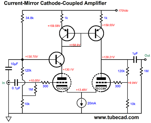
Current-Mirror Cathode-Coupled Amplifier
Note the low B+ voltage of only 170Vdc, which is made possible by the solid-state current mirror. The left triode is cascoded by the NPN transistor, so any variation in the triode's current conduction will be transmitted through the NPN transistor to the left PNP transistor and 1k resistor, which will then relay its varying voltage drop to the right PNP transistor. The result is a push-pull operation at the output. As the right triode conducts more, the right PNP transistor conducts less; and vice versa. Since transistors are cheap and plentiful, nothing stops us from getting extra fancy.
The current mirror just got an upgrade in the above variation. The added PNP transistor improves the current mirror's performance. Note the change in tube and the different input biasing setup for the left triode's grid. We can get even fancier still, as shown below.
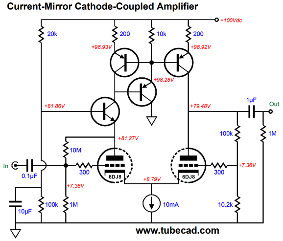
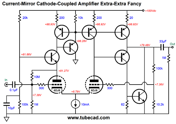
We have added another current-mirror output, which loads the added PNP output transistor, resulting in push-pull operation of sorts. The NPN transistor at the bottom is controlled by the PNP transistor above it and the two transistors form a compound topology that yields low distortion and output impedance. Note the 20-ohm emitter resistor, which results in ten times more current flow than the 200-ohm resistors; in other words, 50mA, not 5mA. In solid-state circuits, such as current-feedback designs, we see current mirrors with multiple outputs.
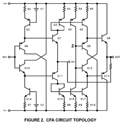
The above schematic appeared in the Intersil AN1213 data sheet. Transistors Q3 & Q4& Q5 define the top current mirror, while transistors Q15 & Q16 & Q17 define the bottom current mirror. Note that two diamond circuits are tucked inside this circuit.
Aikido Cathode-coupled/Grounded-Cathode Amplifier
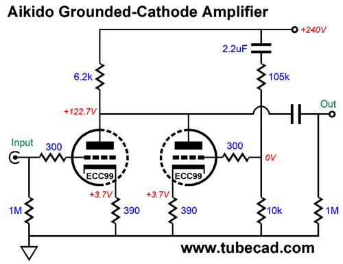
In contrast, the following design consists of a split-load phase splitter driving a grounded-cathode/differential amplifier.
Both cathodes are directly coupled and the input triode's plate indirectly drives the right triode's grid. The result is high gain (about 25 or +28dB) and a stellar PSRR (-54dB). In addition, there is no phase inversion between input and output signals. The Aikido mojo obtains from the careful part value selection, which ensures the best PSRR figure. On the other hand, if high gain were our primary goal, we would deliver more of the left triode's gain to the right triode's grid. For example, if we replace the 4.12k resistor with an 11.7k resistor, the gain climbs to 100 or +40dB, but the PSSR worsens to the point of becoming positive. In other words, we end up getting more power-supply noise that the output than actually is present on the B+ connection. We can replace the shared cathode resistor with a shared constant-current source.
Both versions offer low distortion and a wonderfully high PSRR figure, but I prefer the cathode-resistor version, as it offers slightly more 2nd harmonic distortion. The following design does actually fit the cathode-coupled amplifier topology, as the cathodes are not coupled, but it does show how Aikido mojo can be applied to a single tube, i.e. two similar triodes in one glass envelope.
The left triode develops the signal gain, while the right triode nulls the power-supply noise from the shared output below the common plate resistor. As an added bonus, this configuration yields an output impedance of about 3k with the ECC99.
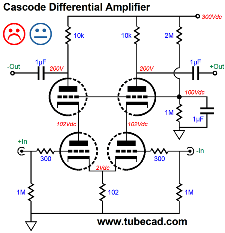
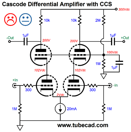
Cascoded Differential Amplifier
The top two triodes could be replaced by two NPN transistors or two N-channel MOSFETs. Like all cascode circuits, this design realizes a high gain and poor PSRR. Replacing the common cathode resistor with a shared constant-current source will both increase the gain and worsen the PSRR, but we do get a bonus in vastly improved CMRR.
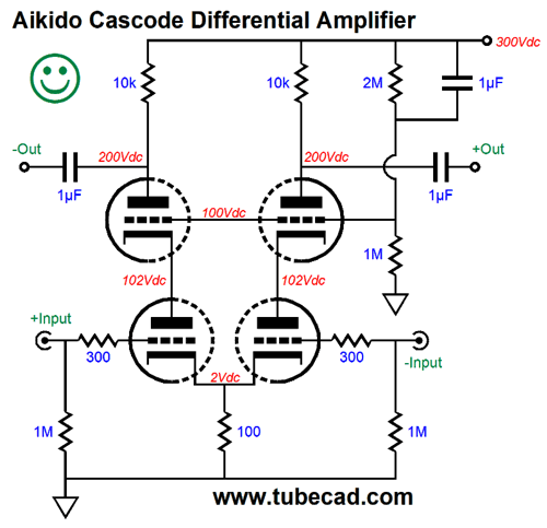
A poor PSRR might not prove to be a problem in a more complex circuit or in a special application, where the following differential stage's high CMRR cleans up the balanced signal leaving the cascoded differential amplifier. For those applications that do require a power-supply-noise-free balanced signal, the following Aikido design drips with Aikido mojo.
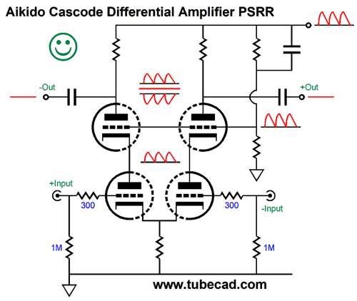
The trick here is that 100% of the power-supply noise's AC signal is fed to the grids of the two top triodes, which then treat the bottom two triodes as cathode resistors; so the top triode behave as a split-load phase splitter, with the power-supply noise as its input signal and which achieves a power-supply noise null at the outputs. The top triodes' current conduction is in phase with the power-supply noise, so the output signal developed at the two top triodes plates is equal in amplitude, but out of phase with the B+ voltage ripple, nulling at the outputs, as +1 + -1 = 0. Although not shown in the above schematic, I would give both top triodes their own 300-ohm grid-stopper resistors.
Note that if we replace the common cathode resistor with a shared constant-current source, the Aikido-mojo deal is off, as the PSRR falls to zero, i.e. 100% of the power-supply noise leaks out of the two outputs.
Blast from the past: Aikido Single-Ended Output Stage
This design was the result of my correspondence with my long-time friend Vance Lohoff, who had gotten me once again interested in grounded-grid output stages. I didn't want to waste the grid by just grounding it, when I knew that I might be able to null the power-supply noise from the output stage's output with the grid. Or, could it be done? The Aikido tricks that worked in a line-stage amplifier with a coupling capacitor at the output no longer worked with a transformer-coupled design; indeed, they worsened the PSRR, not improved it. Our goal is no power-supply noise at the loudspeaker terminals; the speaker does not attach to the plate, however, but to the transformer's secondary. Thus, the output transformer's primary must not see any power-supply-noise induced current variations. In other words, the output tube(s) must not respond to power-supply noise by varying its current conduction. Thus, as the power-supply ripple moves the B+ voltage up, the output triode must not do what it normally would, which is increase its current flow due to the higher plate voltage; instead, it must ignore this noise-induced increase in plate voltage and conduct a steady current flow. The solution is to apply 1/(mu + 1) amount of power-supply noise to the output triode's cathode, which will undo the increase (and decrease) in plate voltages due to power-supply noise, making this noise invisible to the output transformer's primary. I like the above design so much that I am tempted to build such an amplifier with two UBT-1 output transformers (I own four extra) per channel and six EL34 output tubes per channel, with one to drive the other five, resulting in an easy 30W of single-ended glory. The only big problem is the power transformer, as six EL34 tube will draw 9A of current at 6.3V and the each channel will draw a bit over 300mA from the B+ connection.
//JRB
User Guides for GlassWare Software
For those of you who still have old computers running Windows XP (32-bit) or any other Windows 32-bit OS, I have setup the download availability of my old old standards: Tube CAD, SE Amp CAD, and Audio Gadgets. The downloads are at the GlassWare-Yahoo store and the price is only $9.95 for each program. http://glass-ware.stores.yahoo.net/adsoffromgla.html So many have asked that I had to do it. WARNING: THESE THREE PROGRAMS WILL NOT RUN UNDER VISTA 64-Bit or WINDOWS 7 & 8 or any other 64-bit OS. I do plan on remaking all of these programs into 64-bit versions, but it will be a huge ordeal, as programming requires vast chunks of noise-free time, something very rare with children running about. Ideally, I would love to come out with versions that run on iPads and Android-OS tablets.
//JRB
|
|
John Gives
Special Thanks to the Special 65 Only those who have produced a technical white paper or written an article on electronics know just how much time and effort is required to produce one of my posts, as novel circuits must be created, SPICE simulations must be run, schematics must be drawn, and thousands of words must be written.
If you have been reading my posts, you know that my lifetime goal is reaching post number one thousand. I have 586 more to go. My second goal is to gather 1,000 patrons. I have 935 patrons to go. Help me get there.
Kit User Guide PDFs
Only $12.95 TCJ My-Stock DB
Version 2 Improvements *User definable Download for www.glass-ware.com |
||


| www.tubecad.com Copyright © 1999-2018 GlassWare All Rights Reserved |