| John Broskie's Guide to Tube Circuit Analysis & Design |
| 23 March 2010 NEW PCB 1: PS-5 a Simple Tube-Rectified Power Supply
I wasn't kidding when I said that it was simple, as the following schematic makes plain:
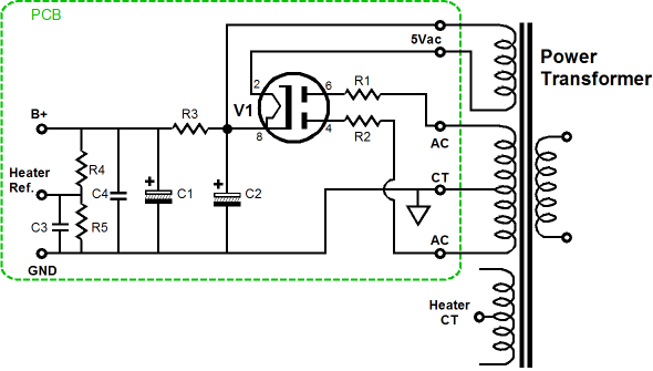
The configuration is classic tube power supply: 5Y3 tube rectifier (5AR4 or 5R4 or WE274B could be used), series anode resistors (R1 & R2), and a simple RC filter (R3 & C1/C4). The PCB requires that a center-tapped power transformer be used to establish the B+ voltage. In addition, the PCB requires a 5Vac winding to heat the rectifier. The PS-5 holds two 47µF/450V capacitors (C1 & C2) and a power resistor (R3). This power resistor can be replaced with a choke. To do so, leave R3 off the PCB and solder the external choke's two leads to R3's solder pads.
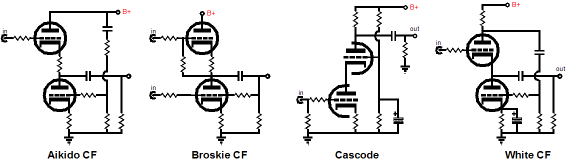
Many topologies, such as the Aikido and Broskie and White cathode followers or cascode or Aikido topology, use triodes standing atop one another, which makes referencing the heater power supply to the B+ power supply a small chore. With one tube atop another and a single heater power supply, the top and bottom heaters cannot share the same heater-to-cathode voltage relationships. With such totem circuits, the safest path is to reference the heater power supply to a voltage equal to one-fourth the B+ voltage; for example, 75V, when using a 300V power supply. The ¼ B-plus voltage ensures that both top and bottom triodes see the same magnitude of heater-to-cathode voltage. The easiest way to establish this voltage relationship is to attach the heater winding's center-tap to the "Heater Ref." pad on the PCB. If the heater winding does not offer a center-tap, then place two 1k resistors in series across the winding and attach the junction between both resistors to the pad labeled "Heater Ref." on the PCB. Speaking of heaters, where is the heater power supply? There isn't one—well at least not on the PCB. Many power transformers intended for use in tube audio gear are woefully weak in heater winding current. Here is an example, a 6.3Vac @ 1A heater winding cannot deliver anywhere near 1A of DC current at 6.3Vdc. When using such a transformer with a 1A load, it's best to give up on using DC and settle for AC on the heaters. In addition, I know that there is an AC-heater fan club out there, as I often get e-mail from some of its members. Well, the PS-5 is just perfect for them. On the other hand, for those who enjoy a bit less humming with their music, the other new PCB, the PS-4, offers DC regulated heater voltage.
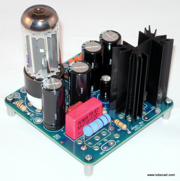
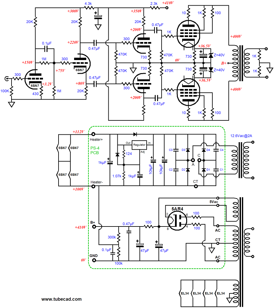
New PCB 2: PS-4 Tube Power Supply The low-voltage regulator is meant to power the tube heaters; the high-voltage power supply, the rest of the tube circuit. The low-voltage regulator’s power supply is flexible enough to allow either a conventional full-wave-bridge and full-wave center-tapped rectifier arrangement or a two-rectifier voltage-doubler configuration, allowing for more latitude in power transformer selection; this regulator can be set to either 6.3V or 12V or 12.6V. Just like the PS-5, the high-voltage portion of the PS-4 power supply uses a tube rectifier, a simple RC filter to achieve a fairly quiet B+ voltage, which can span from 200V to 380V. Once again, the series resistor can be replaced by an external choke. And just like the PS-5, the PS-4 can DC reference the heater regulator to ground or 1/4 of the B+ voltage or left floating, with only a shunting capacitor to ground. The PS-4 power supply PCB is equal to a PS-5 PCB and an H-PS-1 PCB welded together. It is not the equal to the Janus regulator, but then it is neither as expensive nor complex; in addition, it is much more flexible, as it can use any suitable series resistor value in its RC filter, whereas the Janus must use a 1500-ohm resistor. In other words, add a power transformer and the PS-4 PCB makes the basis of a fine tube-circuit power supply, say a tube line-stage amplifier or headphone amplifier or crossover or, even, a small power amplifier.
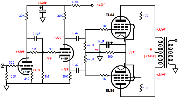
EL84/6BQ5 Push-Pull Power Amplifier
The 6N1P is a fine little tube and about 1Vpk of input signal will bring this amplifier to full output (about 8W) and no feedback loop is employed. The input stage and split-load phase splitter define a CCDA and present an equal amount of B+ noise to the output tubes' grids, which will help reduce the noise at the output. (By the way, the 0.47µF coupling capacitors could be replaced with something smaller, say 0.1µF.) I would use old Dynaco ST35 (also SCA-35) output transformers (about 8k P-to-P), which are stellar performers. A single PS-4 power supply could easily power a stereo version of the amplifier shown above. I would use a 5AR4/GZ34 rectifier, because of its low internal rp. The power supply is shown below.
Note the use of a voltage doubler in the heater circuit. Why? The sad fact is that 6.3Vac is too low to establish a regulated 6.3Vdc. But when 6.3Vac is applied to the voltage doubler, the ensuing DC voltage can sustain a regulated 12Vdc output voltage, as the rectification loses are a smaller part of the 12V regulator's raw DC power supply voltage. The voltage doubler, unlike the federal government, does not work magic; it must pay for the doubled voltage by halving the winding's potential current output. In other words, the 6.3V@6A winding appears as a 12.6V@3A winding, which after rectification losses, can sustain a bit less than 2A of DC current demand.
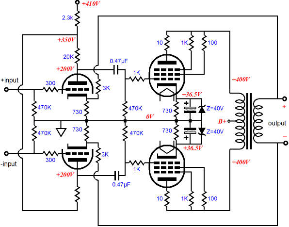
EL34/6CA7 Push-Pull Power Amplifer (The other two most common tube project construction errors are not using grid-stopper resistors and applying too much voltage across heaters and power-supply capacitors. For example the power transformer that would supply 6.3Vac at 6A with a wall voltage of 115Vac might actually deliver 7.3vac with a 3A load and an actual wall voltage of 120Vac. And the power supply capacitors that are rated 450V often see 475Vdc when the intended tube rectifier has been replaced by solid-state rectifiers.) The PS-4 power supply's heater regulator is current limited to about 2.5A, which will allow the 2.4A of current to pass for the four 6SN7 heaters in parallel. (My preference would be to place the heaters in series-parallel and use a 12V regulator output voltage instead, as the rectifier losses would constitute a smaller percentage of the raw DC voltage and I am sure the three-pin voltage regulator would be happier delivering only half the current.) Now, with the input and driver stage tube's heater power supply given over to the PS-4 power supply, a power transformer that holds a 6A heater winding can be used directly with the four EL34 output tubes. To forestall any e-mail asking for a schematic, here is one such possible circuit.
(Speaking of e-mail, I have been killed lately with e-mail, gobs and gobs of it; every hour of the day pours forth more e-mail -- relentlessly, profusely pouring. This is mostly my fault, for two reasons: this website gets well over a million hits a month; so that's a lot of folks thinking about tubes, and the search engines casts big nets. And second, the site is so huge and unwieldy that most people do not realize that their question has already been answered in a previous blog entry or article or old Tube CAD Journal issue. In other words, this site desperately needs to be reorganized, restructured, and simplified.) Back to circuits, the above schematic holds a few surprises; for example, the addition of the 1M resistor across 0.1µF coupling capacitor between the input tube and the split-load phase splitter and the inclusion zener diodes in the output stage. Starting at the end, the zeners set limits to the maximum rectification-induced increase in cathode bias voltage, as they place a 40V ceiling on the cathode resistor's bypass capacitor charging up during loud passages. The EL34s are triode-connected in the extreme, as both screen and G3 are connected to the plate through current-limiting resistors. The output tubes also get 10-ohm resistors before connecting to the primary. Why? It's a small bit of insurance. The resistors work as plate-stopper resistors that dampen out oscillations and they serve as last resort fuses, should the tube arc: better to lose a ten-cent resistor than a hundred-dollar output transformer. Now we move the beginning, this amplifier's input stage uses both an Aikido-like technique to improve PSRR and a CCDA-like choice of the phase splitter plate and cathode resistor values to ensure a constant-current-draw conduction by the first two triodes. The input tube's cathode resistor was purposely left unbypassed and its value was selected to halve the B+ voltage (300Vdc) at input tube's plate. Thus, the triode and its unbypassed cathode resistor will define a virtual resistance equal to the 20k plate resistor, thereby halving the power-supply noise at the plate (and resulting in a gain equal to mu/2). This halved amount of power-supply noise is then cascaded into the split-load phase splitter, which unlike the typical split-load phase splitter setup, will pass the noise from both its outputs in phase and equal in magnitude. See blog 135 for more information. The two 1M resistors split the halved B+ down to a quarter, which then provides the DC reference voltage for the split-load phase splitter. Since the phase splitter undergoes the same voltage swings as the input stage, the current swings though the phase splitter must match the input tube's, as the same 20k cathode resistor value is used I both circuits; but the current swing are in anti-phase between input tub and phase splitter, so the net current draw remains close to constant, thereby greatly relieving the power supply decoupling capacitor. Because the split-load phase splitter does realize unity gain, its slight diminishment of its input signal will subtract from this idealized result. Math-fiends, like myself, can do the simple algebra to work out the exact AC power-supply noise ratio the input tube must establish with its plate resistor and the exact resistor value the split-load phase splitter must use for both its capacitor and plate resistors to bring about exact constant-current draw and exact power-supply noise splitting at the phase splitter's outputs. But the quick answer is that the higher the mu of the triode used as the input and phase-splitter triode, the less we have to worry. From the phase splitter we move to the driver stage. The driver stage consists of two grounded-cathode amplifiers in parallel. Like the input stage, the driver stage also uses a 6SN7 and which also draws an anti-phase AC current between triodes, resulting in a constant DC current draw. These two equal amplifiers also provide a matched power-supply noise contribution their plates, which allows the common-mode noise to cancel in the output stage. The gain from the driver stage is a bit less than the input stage's mu/2. With 6SN7s (or 6CG7s) used throughout, the resulting total voltage gain presented to the output tubes' grids is close to 100, which might seem too high, but would be perfect for an amplifier that forwent an active line-stage amplifier. Or we could use the high gain to drive a negative feedback loop, thereby effectively reducing the amplifier's gain, distortion, and output impedance. I would attach the feedback resistors not to the input tube's cathode, but to the driver tubes' cathodes. Although this configuration will result in higher distortion, the amplifier will prove much more stable, as the feedback loop will contain fewer reactive components. (This helps explain the two-resistor voltage divider on the output transformer's secondary, as shown in the schematic above. Since the secondary automatically provides a balanced output, why ruin it by grounding one lead.) If the two feedback resistors are added, the two 1k resistors across the secondary can be omitted.
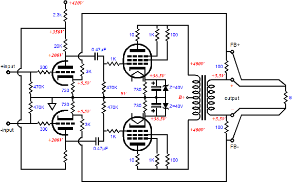
The output transformer's secondary still offers a balanced output, as both terminals present an equal impedance to the load. Balanced in, balanced feedback, balanced out. I am just guessing at a suitable feedback resistor value and I am sure some tweaking will be needed, but this topology is wonderfully symmetrical. By the way, I have built an entire power amplifier based on the circuit shown above, but which used a 12AX7 as the input/driver tube, with only a slight variation on this topology. It worked well and it included the following trick: remote feedback sensing.
The amplifier held four binding posts per channel: two for positive and negative outputs to the loudspeaker and two for feedback. Why? I got the idea from looking a regulated power supply schematics, which presented four terminals on a mono-polar DC output. And I found that the remote sensing of the signal appearing right at the loudspeaker terminals did much to undo the loudspeaker cable faults. The feedback sense cables only conducted a small fraction of the current that the main speaker cables delivered to the speakers, but they experienced the same voltage swings. Back in 1994, John Atwood wrote about this design in the rec.tubes user group:
I used a flat, four-wire, solid-core loudspeaker cable from AudioQuest (F-14 was its name I believe). I tried using dissimilar cables, fat wire for the speakers and thin wire for the remote sensing, but I never liked the results, although in theory dissimilar cables should work best...or do we need a better theory? If flat, solid-core wire is not your cup of tea, you could try one of the many four-wire fancy speaker cables made instead. But is the setup safe? Even if the feedback sense wires were not used, the two 100-ohm resistors, which are normally shunted by the sense wires, come to the rescue, preventing the gain from climbing to open-loop levels. In other words, the remote sensing feedback wires are pretty much optional. Besides, we are not runing a lot of feedback here. By the way, note that the loudspeaker terminals are now referenced to 5.5Vdc. The speaker driver ignores this DC voltage as it is a common-mode signal as far as it voice coil is concerned. No difference, no effect. Nor should we worry too much about this DC voltage as safety hazard, as 5Vdc is not a lot of voltage; 30V, 50V, 100V, on the other hand, is, so the sky is not the limit here. But even if we accidentally short one of the four amplifier speaker terminals to the chassis, the spark will be tiny, as the 3k feedback resistors greatly limit the maximum current flow into the grounded chassis (less than 2mA). By the way, with a 12AX7 in the input tube position, this floating DC voltage is a tiny 1.5Vdc. Of course, if the secondary holds a center tap, that tap can be grounded, which greatly reduce the DC present on the output terminals.
Next Time
//JRB |
E-mail from GlassWare Customers
High-quality, double-sided, extra thick, 2-oz traces, plated-through holes, dual sets of resistor pads and pads for two coupling capacitors. Stereo and mono, octal and 9-pin printed circuit boards available.  Aikido PCBs for as little as $24 http://glass-ware.stores.yahoo.net/
Support the Tube CAD Journal & get an extremely powerful push-pull tube-amplifier simulator for TCJ Push-Pull Calculator
TCJ PPC Version 2 Improvements Rebuilt simulation engine *User definable
Download or CD ROM For more information, please visit our Web site : To purchase, please visit our Yahoo Store: |
|||


| www.tubecad.com Copyright © 1999-2010 GlassWare All Rights Reserved |