| John Broskie's Guide to Tube Circuit Analysis & Design |
25 December 2016 (Updated Dec 27 2016) Merry Christmas! I didn't plan on posting today, but I didn't want to miss a chance to use the following image, one of my favorites.
See December 25 2015's post to read about her.
Push-Pull Minus Push Equals Single-Ended My pick is Leonhard Euler's Identity Equation.
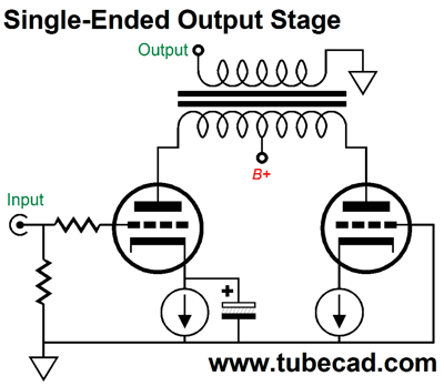
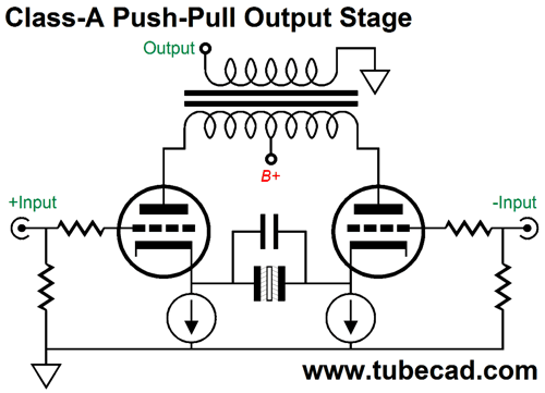
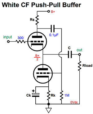
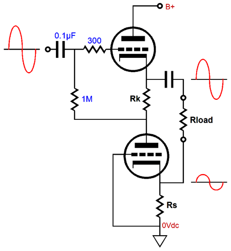
It is short and sweet, filled with all the important things, such as zero, the primary integer, pi, i, e, addition, multiplication, exponentiation, and equality. Returning to the world of electronics, What happens to a push-pull circuit when we subtract pushing half? Answer: we get single-ended operation. Here is an example, which converts a nominally push-pull output stage into a single-ended one. The triode on the right functions as a constant-current source, as its cathode is loaded by one. The triode on the left does all the amplifying. Understand that plate load impedance has fallen, as only half of the primary is loaded. In other words, if the winding ratio had been 20:1, it's only 10:1 now, which means that that primary impedance has fallen to one fourth its plate-to-plate value, as the winding ratio squared equals the impedance ratio. Now, if you are running 16-ohm speakers, you could attach them to the 4-ohm output tap on the secondary, so the old load impedance is restored. By the way, what happens if we remove the remaining electrolytic capacitor from the above circuit? We get no amplification at all. What happens if we add a second the electrolytic capacitor to the above circuit shunting the right constant-current source and drive both grids with a balanced input signal? We get push-pull operation in class-A. Well, we can actually push the output stage past class-A, but we risk over-charging the two electrolytic capacitors, which will lead to under biasing the output tubes, which if severe enough, can turn them off altogether for a short period, resulting in momentary loss of output, i.e. blocking distortion. Class-A means living within our idle current. Here is a fun push-pull setup, wherein each triode gets its own constant-current source to set its idle current, while the non-polarized electrolytic and film capacitors bridge the two cathodes to AC signals.
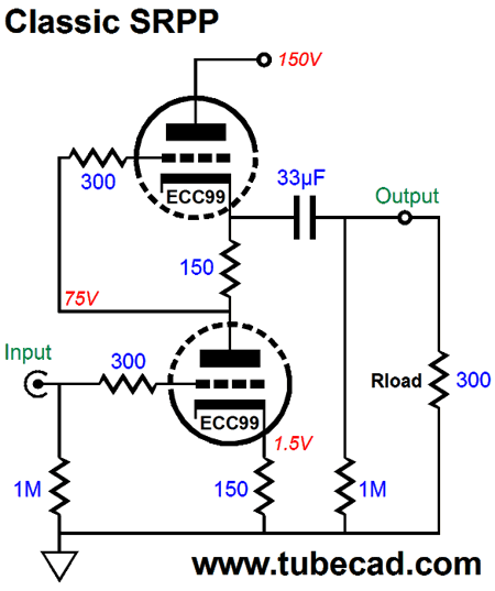
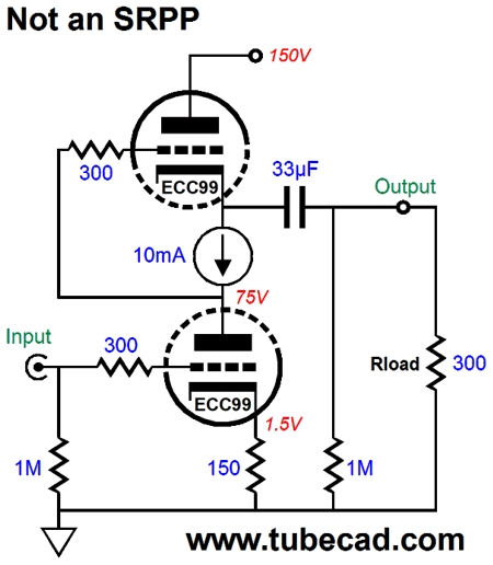
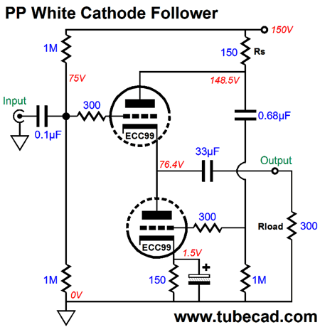
Now that we have mentally warmed up, we can move on the three reflexive circuits, i.e. the SRPP, White cathode follower, and SRCFPP. All three belong to a triumvirate of lazy push-pull circuits, circuits that achieve class-A push-pull operation without receiving a balanced pair of input signals, making use of a single unbalanced signal at just one triode's grid. How does the other triode get its own signal at its grid? Each circuit uses a current-sense resistor to develop the needed anti-phase signal to drive the opposing triode. All three circuits are entirely load dependent; a different load impedance requires a different current-sense resistor value. The SRPP is the darling of tube fanciers, as it is super simple and it solves the problem of what to do with the extra triode found in dual-triode tubes such as the 6DJ8, 6SN7, and 12AU7. The SRPP's formula for the optimal current-sense resistor value is easy enough: Rs = (rp + 2Rload) / mu In fact, this same formula is used with the other two lazy circuits. With a cathode-to-plate voltage of 75V and 10mA of idle current, an ECC99 exhibits a plate resistance of 2700 ohms and a mu 22, which the above formula decrees that a 150-ohm current-sense resistor be used. SPICE simulations conformed the formula's prediction.
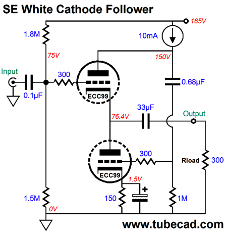
The ECC99 is a robust twin triode tube that can dissipate an amazing amount of plate dissipation, i.e. 5W per triode. In the above circuit it idles at 10mA, which means that the peak output current swing is 20mA, which in turn means a peak voltage swing of 6V into the 300-ohm load. If we replace the current-sense resistor with constant-current source, we end up entirely undoing the push-pull operation, leaving only single-ended operation.
It is no longer an SRPP, as we have undone the push-pull operation. Some call this circuit a mu follower. Many either believe that this is the ultimate expression of the SRPP topology or that this actually how all SRPP's work. Ah, distinctly I remember it was in the bleak late 1990s; and each separate angry email wrought its ghost upon my soul. The same three pained expression of dissatisfaction and resentment. "All Circlotron must by necessity operate exclusively in class-A." "Bruce Rozenblit's patented OTL circuit had been vouchsafed by the luminaries at the US Patent Office, so no debate was permissible." "The SRPP holds no PP, as it is purely a single-ended effort, the top triode functioning as a constant-current source and as a cathode follower at once, achieving the miracle by varying the current flow through the top triode, which is a great trick for something that draws a constant current." All three claims were repeated over and over, like some deranged magical enchantment. Then it ended. Somewhere mid 2000's, the three claims grew silent. Why? Super good question. My guess is that enough readers had access to a SPICE program and they were able to perform their own tests. In the simulations, no exclusive class-A operation could be found, just everyday class-AB; Bruce's patent didn't ensure equal but opposite phase conduction for the OTL's output tubes; and the SRPP pushed and pulled, true to its name. Thus, SPICE won over those for whom reasoned arguments left unpersuaded. At the same time, however, SPICE allowed many to create impossible circuits. For example, the above current-source-laden circuit works perfectly well in SPICE, but would prove impossible to reproduce in reality with the same performance. Seriously? Why? In SPICE, a current source is magical device that finds no equivalent in reality, as it produces current flow in the absence of a power supply; it is a power source in its own right.
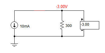
The above is a screen capture of a SPICE current source in action. Note that no power supply or battery is present. In reality, constant-current sources are actually current regulators or current limiters; they do not produce current out of thin air. Moreover, they cannot work below some relatively high voltage, say 1V to 3V. Is this a problem? Yes, it is, as this means that the circuit shown above will choke with a real current source, such as the LM334, as only 1.5V of voltage spans from the bottom triode's plate to the top triode's cathode. Think about, let's say that the LM334 could, miraculously enough, work down to 0V across its leads. Then the maximum positive grid-voltage swing the top triode could experience would be 1.5V, the voltage drop across the current source at idle. But a real LM334 will stop working once its voltage differential falls below 1V. In contrast, a SPICE current source can swing the grid up past its cathode voltage, as the following SPICE generated graph shows.
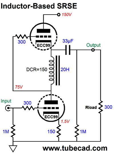
The thick, blue line reveals the top triode's grid-to-cathode voltage. After a 1mS delay, a 1Vpk sinewave is presented to the bottom triode's grid. The constant-current source sets a strict negative voltage swing into the load of -3Vpk, as 10mA against 300 ohms equals 3V. The top triode is not limited by the constant-current source; indeed, the constant-current source performs the magic trick of swinging the top triode's grid 4V more positive than its cathode. Unfortunately for us living in the non-virtual-reality world, this magic trick is just a fantasy. The workaround would be to add an internal coupling capacitor and a few extra resistors and FET or MOSFET—and bump up the B+ voltage to something closer to 160V. Another possible workaround is to use a large-valued inductor, say at least 20H) with a DCR of 150 ohms. The inductor can swing the top grid several volts more positive than the top cathode, but it, too, imposes an idle-current limit to negative voltage swings into the load impedance, the same -3Vpk limit.
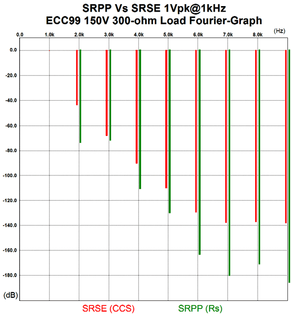
Okay, returning to the virtual-reality SPICE version of the SRSE, the top triode experiences all the current variations, while the bottom triode sees a constant current flow. The 300-ohm load impedance sees the difference between the top triode's conduction minus the 10mA of steady current flow. For example, in order to swing +/-10mA of current into the load, the top triode must increase its conduction up from 10mA to 20mA and then drop its current flow to zero to allow the constant-current source to deliver all its flow into the load. The great advantage to the SRSE topology is that gain increase from 1.9 for the resistor-based version to 15 for the constant-current-source version. In the distortion contest, the winner is clear.
Forgive the Christmas color scheme. Ho ho. The SRPP with the current-sense resistor puts out far less than 0.1% distortion, whereas the SRSE with the constant-current source, the SPICE best-case-possible current source, does a little better than 1%. The SRPP can swing up to 6Vpk into the 300-ohm load, while the SRSE can only swing 3Vpk. Okay, was this a slam dunk? Did the SRPP with current-sense resistor totally kick butt? Maybe, maybe not. Note that the SRSE delivered more 2nd harmonic distortion. I can easily imagine many preferring the sound from the SRSE, finding it far more musical and warm sounding. Of course, even this scenario can be flipped. The same listener who reveled in the SRSE's romantic presentation of an old Verve jazz LP may prefer the SRPP with a thick orchestral recording, finding the clearer presentation well suited to complex, hundred-instrument performances. Sometime you fell like a nut; sometimes you don't.
Single-Ended White Cathode Follower
Many, if not most, do not want to use the optimal White cathode follower setup shown above, preferring to make the current-sense resistor's value as high as possible, which logically ends in using a constant-current source instead.
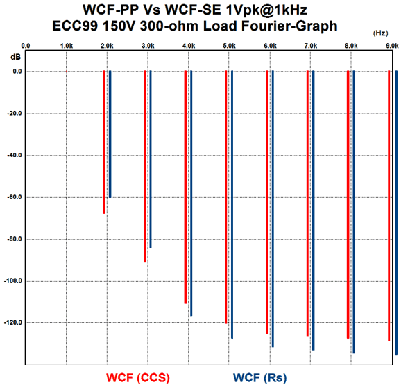
Placing a constant-current source in series with the triodes means that we have departed push-pull operation, as the top triode must constantly draw a fixed amount of current, which means that the bottom triode must do all the work, swinging up to twice the idle current and then swinging down to zero conduction. With a 10mA constant-current source, the maximum output voltage swing would be 3Vpk into 300 ohms. In contrast, the optimal push-pull version will swing 6Vpk into 300 -ohm, as each triode can deliver twice the idle current into the load. In terms of performance, the constant-current source version offers a closer appropriation to unity-gain (0.94 versus 0.8, in this example), far lower output impedance (5 ohms versus 45 ohms), insanely improved PSRR (near negative infinity versus -9.3dB). What about the all important harmonic distortion? Here is the SPICE generated results.
The optimal push-pull version of the White cathode follower delivers lower 4th and above harmonics, while the constant-current source version offers lower 2nd and 3rd harmonics. So which won? I cannot say. I can say, however, that if you need stellar PSRR and low output impedance, but not heavy power delivery, say driving a passive LCR RIAA EQ network, then the constant-current source version clearly wins. Or does it? In the absence of a DC feedback mechanism to keep the DC voltage inline with our desires, placing a constant-current source in series with an ultra-high impedance termination, which the top triode's plate presents in this topology (in DC terms, not AC terms), creates huge headaches. Trust me. Placing constant-current source in series with an ultra-low impedance termination, such as a cathode, however, works well. The solution is to use one of my compliant-current sources (CCCS) instead.
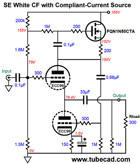
The
FQN1N50CTA is a high-voltage (500V) MOSFET in a TO-92 package. It is rated for 0.89W and two can be bought for less than $1. Now, the idle is set by the 150-ohm cathode resistor, not a constant-current source.
Single-Ended SRCF
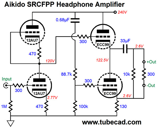
Like the White cathode follower, the SRCFPP is a unity-gain buffer, a buffer which can swing twice the idle current into the load. Here is a fun arrangement, which uses a 12AU7 as the input tube and an ECC99 as the output tube.
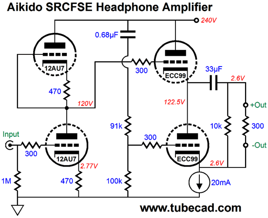
The output impedance is about 80 ohms; the PSRR, about -60dB; and the gain, about 6 (+15.5dB). This makes a truly sweet headphone amplifier for 300-ohm headphones, such as those made by Sennheiser. (I plan on building a headphone amplifier based on this circuit with two Aikido Noval Mono PCBs and two PS-1 power supplies, one per channel. Overkill? Yes. I want to not share ground connections between the channels in the enclosure, only in the signal source, so I welcome the balanced output. The idea behind this project is to prevent a shared ground that would allow signal currents to travel down the wrong channel's ground connection.) Undoing the push-pull operation requires replacing the current-sense resistor with a constant-current source. Unlike the SRPP and White cathode follower, the constant-current source in series with the cathode and ground is no problem.
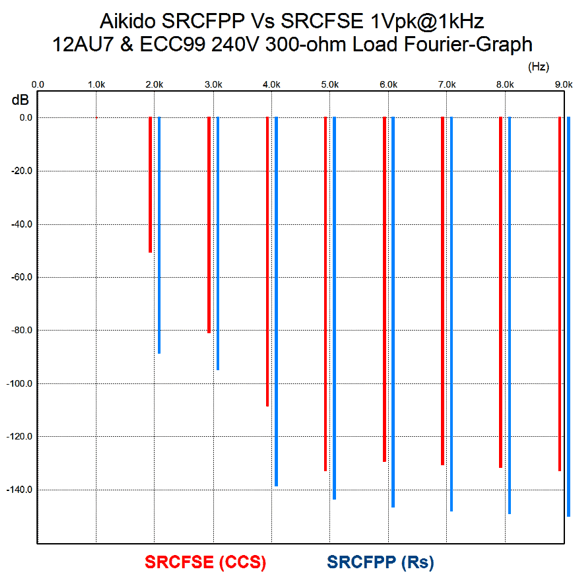
What might prove to be a problem, however, is the constant-current source starving for voltage. One workaround would be to place a 2M in parallel with the 0.68µF capacitor. Note the high B+ voltage (250Vdc) and the high idle current (20mA), both of which allow 6Vpk output voltage swings into 300-ohms, compared to the push-pull version's 12Vpk swings. Unlike the previous shootout, the gain, output impedance, and PSRR are pretty much the same between the push-pull and single-ended versions. What does differ, however, is the harmonic distortion, as the following graph shows.
The push-pull version offers significantly less harmonic distortion. How can this be, John, constant-current sources always make things better? Actually, they don't. For example, a cathode follower's PSRR worsens with a constant-current source load over a resistor load. For those who must use the tree-contact headphone plug, the following variation could be used.
The output transformer allows us to either run a balanced output or a regular shared-ground output. In addition, it allows easy phase reversals and the ability to use either high- or low-impedance headphones. A winding ratio of 2:1 results in an impedance ratio of 4:1, so 300-ohm loads will be reflected at the primary as 1,200-ohms loads. Assuming 50-ohm headphones as the low-impedance load, the winding ratio should be 5:1, as 25 times 50 is 1250, close enough. I ran some SPICE simulations on the above circuit and the results were so fine, I am too embarrassed to show them.
SE Vs PP Update
The single-ended versions with a constant-current source delivered half the peak output swing. The White cathode follower improved the most, as its output impedance and PSRR fell considerably; its distortion was more than halved. Across the board, the SRCFPP suffered from using a constant-current source over a current-sense resistor. And the SRPP delivered a mixed bag of results, as the output impedance fell greatly, while the PSRR improved and the gain climbed, but the distortion substantially worsened by twenty-fold. Note that the SRCFPP circuit was the straight version shown below, except that no Rk resistor or coupling capacitor at the input.
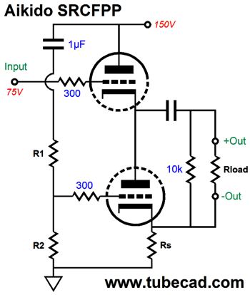
Instead, we can use the Aikido version of the SRCFPP, which offers a significantly improved PSRR.
By inject a small portion of the power-supply noise into the bottom triode's grid, we create a power-supply-noise null across the load resistance.
//JRB
If you have been reading my posts, you know that my lifetime goal is reaching post number one thousand. I have 634 more to go. My second goal is to gather 1,000 patrons. I have 976 patrons to go. If you enjoyed reading this post from me, then you might consider becoming one of my patrons at Patreon.com.
User Guides for GlassWare Software
For those of you who still have old computers running Windows XP (32-bit) or any other Windows 32-bit OS, I have setup the download availability of my old old standards: Tube CAD, SE Amp CAD, and Audio Gadgets. The downloads are at the GlassWare-Yahoo store and the price is only $9.95 for each program. http://glass-ware.stores.yahoo.net/adsoffromgla.html So many have asked that I had to do it. WARNING: THESE THREE PROGRAMS WILL NOT RUN UNDER VISTA 64-Bit or WINDOWS 7 & 8 or any other 64-bit OS. I do plan on remaking all of these programs into 64-bit versions, but it will be a huge ordeal, as programming requires vast chunks of noise-free time, something very rare with children running about. Ideally, I would love to come out with versions that run on iPads and Android-OS tablets. //JRB |
Kit User Guide PDFs
E-mail from GlassWare Customers
High-quality, double-sided, extra thick, 2-oz traces, plated-through holes, dual sets of resistor pads and pads for two coupling capacitors. Stereo and mono, octal and 9-pin printed circuit boards available.  Aikido PCBs for as little as $24 http://glass-ware.stores.yahoo.net/ Support the Tube CAD Journal & get an extremely powerful push-pull tube-amplifier simulator for TCJ Push-Pull Calculator
TCJ PPC Version 2 Improvements Rebuilt simulation engine *User definable
Download or CD ROM For more information, please visit our Web site : To purchase, please visit our Yahoo Store: |
|||||||||||||||||||||||||||||||||||||||||||||||||||||||||||||||||||||||||||||||||||


| www.tubecad.com Copyright © 1999-2016 GlassWare All Rights Reserved |