| John Broskie's Guide to Tube Circuit Analysis & Design |
|
08 May 2007 Turmoil It seems that I have caused turmoil in tube land; the angry towns people are taking up pitchforks and torches, and soon they will break down my door. What was my offense? Surely it would have to be something spectacular, like describing a D-getter as a halo or confusing the 12AV7 for the 5965 or by gratuitously quoting Shakespeare. No, much worse than any of these, my sin was not being sarcastic enough. I began my last blog entry with
The “—thanks Bruce” portion was my subtle way of rapping Bruce Rozenblit on the knuckles for misnaming the cathode-coupled amplifier the “grounded-grid amplifier.” I should have written, “—no thanks to Bruce Rozenblit, whose taxonomic howler has made already murky waters murkier still.” Because I didn’t write that last fragment, I am seen as thanking Bruce for a job well done. I am not. In fact, when I reviewed his book, Audio Reality: Myths Debunked...Truths Revealed, I wrote that he had misnamed his line stage amplifier:
(By the way, I received some criticism for my having endorsed his book so highly. A few readers who bought his book on my recommendation told me that they were disappointed that his book wasn’t more like the Tube CAD Journal. Well, it isn’t, but that doesn’t mean it isn’t a good starting point from many beginners. In other words, I still stand by my recommendation; besides, in a world where equipment stands and power cords can cost $5,000, at $29 it’s a bargain. Yes, I do not think his OTL-zener-trick patent is worth any of the commotion that his fans announce so loudly, but I do think that the rest of his circuits are otherwise solid, if not a bit stodgy—in a good way, having had to repair many uncultivated and too-imaginative circuits for friends, I prefer stodgy. And I truly enjoyed reading his engineering philosophy, particularly the part where he writes about talking to two Afro-American audiophiles at a high-end show.) So, are we done? No. The topic of circuit designation is dispiriting. The SRPP goes by four or five names; and most single-tube topologies have at least two names—even the cathode follower is also known as the “grounded-plate amplifier.” I wish it wasn’t so. But can you ever put a genie back into a bottle? On NPR radio shows, NPR for God’s sake, I hear the word “enormity” used to describe huge things, even huge good things like lotto winnings or number of adoring fans, but never moral outrages—for monstrous offenses the word “enormous” is often used. Just today, I read of the “fulsome” praise heaped on Queen Elisabeth; did the reporter mean “offensively flattering” or just copious or, possibly, pompous? The sad reality, speaking of audio reality, is that I get at least one e-mail a week where the reader calls the cathode-coupled amplifier a “grounded-grid” amplifier. And it easy to see why he does: Bruce has named his line stage amplifier such and it is popular, besides the reader is quite unlikely to have read many 60-yearold electrical engineer textbooks (very few share my fetish) and on the DIY sites he reads that is what the circuit is called. Do not get me wrong; I wish it were otherwise. In fact, here is the irony of the situation, in these pages, I have decried sloppy nomenclature—the procedure of assigning names to the kinds and groups listed in a taxonomic classification. For example, from the Cars, Planes, Circlotron article:
And here is what I wrote on Pawels circuit:
And on hybrid topologies:
And from the Partial Feedback Amplifiers article.
Speaking of “nice,” it once meant wanton, profligate, as in Shakespeare’s Anthony and Cleopatra:
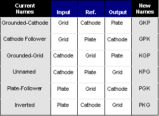
(In all honesty, I expected some flack for quoting Shakespeare in the last blog, as dead white guys go, William Shakespeare is about as dead and white as they come. And quoting him or any other dead white guy is minor sin these days, wherein we bow to the multicultural imperative, the view that the all the world’s cultures merit equal respect and scholarly interest, except the Western culture.) Six years ago, I even offered my own cure to the circuit-naming problem:
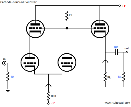
Cathode-coupled amplifiers
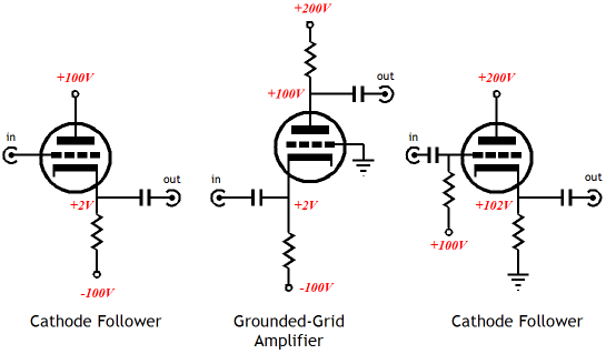
Let's ignore the active load in place of a plate resistor and let's deconstruct the circuit.
Three simple, single-tube topologies make up the more complex circuit. (I have used the same triode in each and have used typical voltage values.) The first is a simple cathode follower that receives the input signal; next, the grounded-grid amplifier amplifies the signal, without inverting its phase; then the cathode follower buffers the output. Note how many of the voltages match and since they do, we can eliminate four coupling capacitors, which brings us back to the complex circuit. Now, what if we didn't need any gain, but we did want the widest bandwidth possible. The great feature of a cathode follower is its low-input capacitance. This makes sense, as the grid-to-plate capacitance is small and the larger grid-to-cathode capacitance is mitigated by the cathode following the grid in phase. Well, what if the plate also followed the grid? Such an arrangement would effectively nullify the grid-to-plate capacitance. The following circuit shows how this can be realized.
100% of the output signal is fed back to the grounded-grid amplifier’s grid (remember the deconstructing, I am referring to the rightmost bottom triode’s grid), which will force the amplifier to produce a near-unity-gain output. this arrangement will also supercharge the output cathode follower’s performance, as its distortion and output impedance will be greatly reduced by the 100% feedback ratio. The 100% feedback also causes the coupled cathodes to more closely track the input signal (had the right triode’s grid been grounded, the cathode will only move 50% of the swing that the input grid sees), which greatly reduces the effective grid-to-cathode capacitance, which, in turn, greatly extends the high-frequency bandwidth. The input cathode follower is now augmented in that its plate sees the same signal as its input grid, as the leftmost top cathode follower follows the output signal. All in all, not a bad circuit, but of course there is always room for improvement.
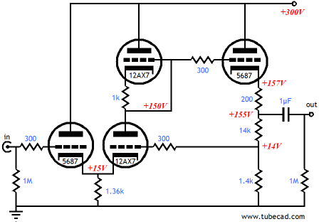
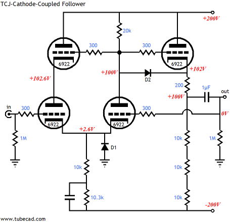
Now the circuit is fleshed out, with the missing parts restored to their rightful places. For example, grid-stopper resistors—those unsung and under appreciated circuit savers, abound. The Tube CAD Journal signature protective diodes stand ready to keep huge hundred-volt voltage differentials from developing between grid and cathodes at start up, when the tubes are cold and not conducting (just imagine the grid being 400 volts more positive than the cathode. And, finally, the Aikido-like noise reduction trick of bypassing the bottommost shared cathode resistor, which injects just enough power supply noise-induced current to flow through the 20k plate resistor to counter the power supply noise at the output. So is this circuit a modified cathode follower or a hotrodded cathode-coupled amplifier? Or, was Bruce right after all and the circuit is a super-mega grounded-grid amplifier? Or, how about, using my own system, the GPK-KGP-GPK amplifier? To be frank, I like the “TCJ cathode-coupled follower” best, although I must admit that GPK-KGP-GPK amplifier does have a ring to it. A less complex, but equally interesting, circuit is shown below.
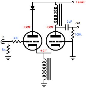
The inductors work as constant current sources, but with out displacing much voltage, assuming a DCR of 100 ohms. The diode can be removed, as it only serves to make up for the voltage drop across the top choke. Note the low B+ voltage. Note the paucity of parts. Imagine a chassis with two tubes and four chokes. If only we didn't have to deal with the coupling capacitor:
But then, who say that we have to put up with it. (Now, what if we lost the 1M grid and the 300-ohm grid-stopper resistors, replacing the first with a choke and the second with a ferrite bead...a resistor and capacitor free line stage amplifier—in marketing terms, that has got to be worth at least $5,000. Or, am I not being sarcastic enough ;} //JRB
|
Now accepting Only $12.95
Download or CD ROM www.glass-ware.com
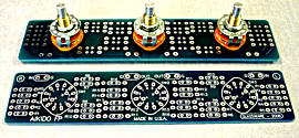
High-quality, double-sided, extra thick, 2-oz traces, plated-through holes, dual sets of resistor pads and pads for two coupling capacitors. Stereo and mono, octal and 9-pin printed circuit boards available.  Aikido PCBs for as little as $24 http://glass-ware.stores.yahoo.net/
The TCJ Stepped Attenuator The center knob controls both channels, and offers six large decrements; the flanking knobs offer six fine decrements for each channel, creating a volume control and balance control in one easy-to-use stepped attenuator. This clever attenuator uses fewer resistors (only 32) than would be expected from a conventional 32-position stepped attenuator, as two series attenuators would need a total of 72 resistors; and two ladder attenuators would require 140 resistors. In addition, the PCB holds dual sets of resistor pads, one wide and one narrow, so that axial (composition, wire-wound, and film) and radial (thick-film and bulk-foil) resistors can be used without extra lead bending. Although designed to go with the Aikido amplifier, it can be used anywhere a high-quality attenuator is needed, whether passive or active. For example, it would make a first-rate foundation to an excellent passive line box. Visit our Yahoo Store for more details: http://glass-ware.stores.yahoo.net/
The Tube CAD Journal's first companion program, TCJ Filter Design lets you design a filter or crossover (passive, solid-state or tube) without having to check out thick textbooks from the library and without having to breakout the scientific calculator. This program's goal is to provide a quick and easy display not only of the frequency response, but also of the resistor and capacitor values for a passive and active filters and crossovers. TCJ Filter Design is easy to use, but not lightweight, holding over 60 different filter topologies and up to four filter alignments: While the program’s main concern is active filters, solid-state and tube, it also does passive filters. In fact, it can be used to calculate passive crossovers for use with speakers by entering 8 ohms as the terminating resistance. Click on the image below to see the full screen capture.
Tube crossovers are a major part of this program; both buffered and un-buffered tube based filters along with mono-polar and bipolar power supply topologies are covered. Available on a CD-ROM and a downloadable version (4 Megabytes). Download or CD ROM
|
|||


| www.tubecad.com Copyright © 1999-2007 GlassWare All Rights Reserved |