| John Broskie's Guide to Tube Circuit Analysis & Design |
09 May 2005  Broskie Auto-Bias Circuit
 Schematic typos 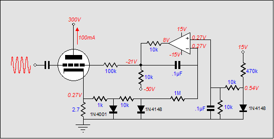
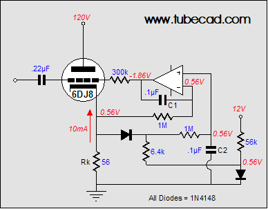
However, once the output stage jumps out of class-A into class-AB operation, the DC servo will see a net DC increase at its inverting input and it will strive to bring the amplifier back into line with its reference voltage, but at the same time the capacitor will begin to charge to higher voltage, which will throw the bias voltage off (negatively) until the input signal subsides enough to let it discharge back to its idle value, as shown in the graph below. 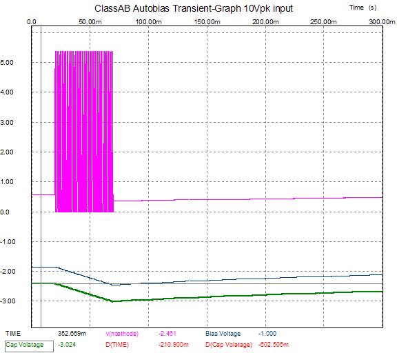 The graph above shows the tube's current conduction in hot pink, the grid bias voltage in blue, and the capacitor’s voltage differential in green. The signal burst excessively charges the DC servo's capacitor and its output voltage is thrown off the mark by over half a volt (602mV). The principle behind the clipping-style auto-bias circuits is also simple: monitor the tube’s current conduction while it is operating in class-A; ignore its AC conduction beyond class-A, when the tube moves into class-B. The clipping diode shorts to ground error signals greater than its forward voltage. In other words, the clipping diode's forwards voltage creates a window that extends from 0V to the cathode-to-anode voltage required to turn the diode on (silicon diodes also have cathodes). By setting the DC servo’s reference voltage to half of the diode's forwards voltage, we ensure that the window of current encompasses the extent of class-A operation that the tube(s) can undergo, without one tube cutting off, while the other conducts beyond the window’s top edge. This plan works perfectly with no input signal; well with large input signals that extend deep into class-B; not so well with input signal just beyond class-A operation of the output tubes. 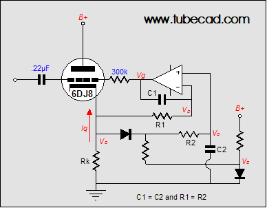 Broskie auto-bias circuit How does it work? The triode's idle current must be great enough to establish the same voltage across the cathode resistor as the diode’s forward voltage, as this voltage is used as the servo’s reference voltage. (Imagine that the diode that attaches to the tube’s cathode has been removed from the circuit, which it effectively is at idle). The OpAmp compares the cathode voltage to its reference voltage and then establishes and maintains grid-bias voltage required to meet this compulsory idle current. 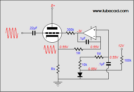
Now, as long as the tube runs within the boundary of twice the diode’s forward voltage (Vd) at its cathode, the triode will operate in pure class-A and the DC servo will handle setting the bias voltage quite nicely. 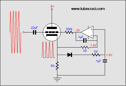
Once the tube leaves the confines of class-A, however, its cathode voltage will exceed twice Vd and the diode attached to the cathode will begin to conduct, charging C2 as a result. Since capacitors C1 and C2 are equal in value, as are resistors R1 and R2, the rate of charging will be the same between both capacitors. In other words, the DC servo’s reference voltage will be thrown off in a matching way as the servo’s own capacitor is thrown off. It’s much like docking a boat to a floating dock: no matter how much the tide rises or falls, the boat will remain in the same relation to the dock.
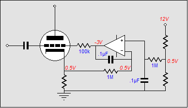
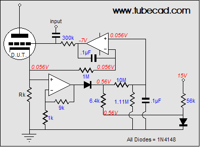
In the schematic above, we see all the part values and voltages labeled. In SPICE simulations, these values worked best (and of course, real values may differ). How well does it work? 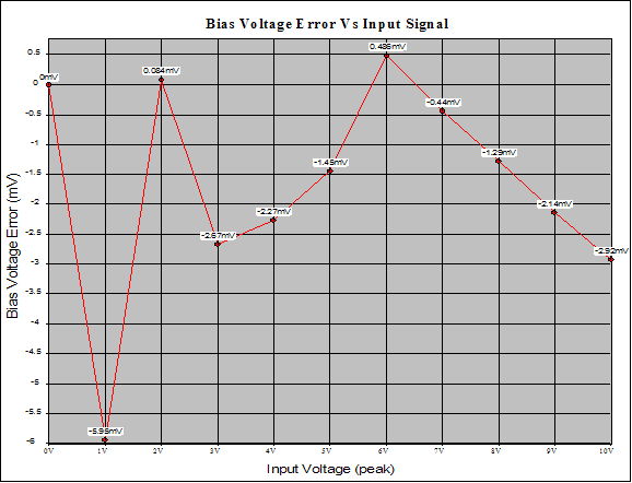 The above graph shows the circuit’s bias voltage error in millivolts against input signal. Interestingly, the greatest departure from the desired bias voltage occurs at the 1-volt input signal. This makes sense, as the 6DJ8 is approaching the class-A boundary with this input signal and the tube undergoes a good bit of rectification; i.e. it linearity suffers because it is much easier to turn on a triode than to turn it off. This uneven handling of the sine wave ends up charging the servo’s capacitor C1, but the voltage reference’s capacitor doesn’t see any of the rectification, so it isn’t further charged. So, how good is the Broskie auto-bias circuit? One problem this circuit faces is that the tube’s cathode is burdened by the presence of the 1N4148 diode and the 6.4k resistor. In the act of sampling the cathode voltage, we end up influencing the tube by giving it a nonlinear cathode load. A second, and much more damning, problem is found in the relatively high-valued cathode resistor (56-ohms in this example). Ideally, we should be able to choose whether or not the triode receives a little or a lot of cathode degeneration. The workaround for the last problem is to amplify the cathode voltage before using the diode to set a voltage threshold. In the schematic below, we see an additional OpAmp that both buffers the cathode voltage from the diode and provides voltage gain, allowing us to use a much smaller-valued cathode resistor. (When the Broskie auto-bias circuit is used with MOSFETs or transistors, this feature will become much more important, because of the much lower power supply voltages used and much higher currents experienced through the output devices.)
Note that a single 1M resistor is missing from the voltage reference portion of the circuit; in its stead, a 10M and 1.11M resistor are used to create a 10% voltage divider whose output impedance equals 1M, the same resistor value that the servo uses. (10M in parallel with 1.11M equals 1M.) Unfortunately, 1% resistors above 2M are hard to find. OpAmps, on the other hand, are readily available and cheap. The circuit below uses an additional OpAmp to buffer the voltage reference’s output before feeding a fairly low-impedance voltage divider. The source voltage is first amplified by 100 and the voltage-reference voltage is divided by 100. 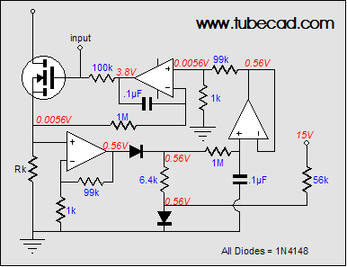
Three-OpAmp Broskie auto-bias circuit How well does the dual-OpAmp version of the Broskie auto-bias circuit work? Much better than the previous version, it turns out. 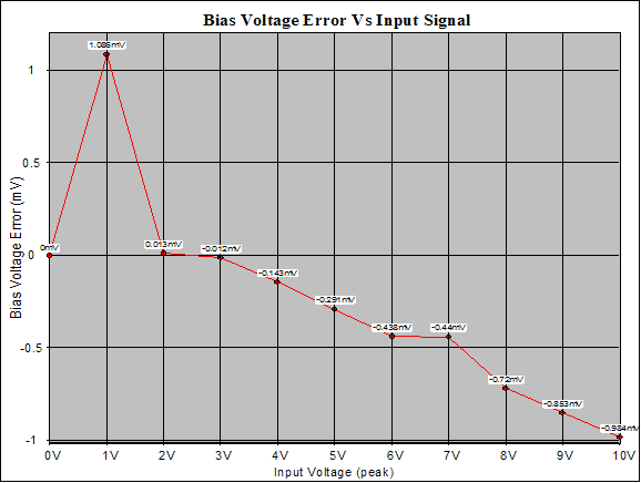
Not too bad. The bias voltage is only once thrown off by more than 1mV (1.084mV, to be exact). Once again the most egregious error occurs at an input signal of 1 volt, but beyond that input level, the auto-bias circuit works admirably. So much so, in fact, that some of my friends are wondering why I didn’t apply for a patent on this circuit or sell it to some big-name audio-equipment company or, at the very least, show them and no one else. Why did I choose none of the above? Not my style, is as good a answer as any. 
I don’t believe in patents for circuit topologies and I don’t like the idea of only a few people benefiting from a good circuit. (I know a few of my friends are pulling their hair out as they read this: what’s the point of being a magician if you keep revealing how your tricks are done, and if you aren’t willing to make a bundle performing them?) I do ask that if you use the circuit in a commercial product, give me credit for having come up with it. Simplest clipping-auto-bias circuit //JRB |
Only $12.95
Download or CD ROM www.glass-ware.com
|
|||


| www.tubecad.com Copyright © 1999-2005 GlassWare All Rights Reserved |