| John Broskie's Guide to Tube Circuit Analysis & Design |
 All-Tube SRPP on Steroids All-Tube SRPP on Steroids
|
||||
16 February 2005 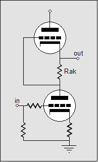
All-tube SRPP on steroids OK, understanding is great, but why turn a tube circuit into a solid-state one? One answer is that as we become fluent in translating technologies, we can translate solid-state circuits into tube circuits. In the last blog entry ended with an all-solid-state power amplifier based on the SRPP topology. Two OpAmps controlled two N-channel MOSFET output devices. Now, the question is How do we translate this circuit into an all-tube one? First, whenever you see an OpAmp, think of replacing it with a single triode, as the triode is analogous to a current-feedback OpAmp in that offers both a high-impedance and a low-impedance inputs. Thus, we should strive to swap the MOSFETs with output tubes and the OpAmps with single triodes (although more could readily be used). 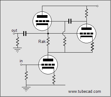
If no load is attached to the top triode's cathode, the bottom output triode would only be loaded with a constant-current source. Once again, we have an example of seeing what is common in spite of different technologies, as this circuit is functionally the same as the popular two-transistor, constant-current source shown below. (The transistor on the right will fight to keep the voltage drop across the sense resistor equal to its base-to-emitter voltage, usually 0.7 volts). 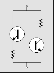
Now, let’s look at how the picture radically changes when we attach a load to the top output triode’s cathode. Let’s back up a bit and use a simple two-tube SRPP instead. If the load is a dead short to ground (via large-valued coupling capacitor or a high-voltage battery), the bottom triode will never know (in AC terms) that the top triode even exists; instead, the bottom triode will function as if its plate resistor had been terminated into a high-quality regulated power supply, as the top triode current circuit does not encompass resistor Rak (assuming that its grid draws no current, which is a safe assumption). So, we have gone from loading the bottom output tube with a constant-current source to loading it with a low-valued plate resistor, in this case. The top output triode does know that the bottom triode exists as its input signal derives from the variation in current flowing through the bottom output tube and resistor Rak. Note that the two output tubes work in anti-current phase to each other: as the bottom tube conducts more, the top conducts less; as the bottom tube conducts less, the top conducts more. This means that the load—whether it be ground, a resistor, or a battery—will see the difference in current conduction between top and bottom output tubes. If they conducted in phase or if their conduction remained constant, the load would never see a varying current draw, as the top and bottom output tubes would effectively define an all inclusive current path; and their nexus would never varying in voltage, in spite of large current variations. This picture only slightly alters in the more complex circuit that holds the added grounded-cathode amplifier (assuming that the added triode draws only a small percentage of the current that the output tubes draw). Now for the bottom half of the SRPP amplifier. We add an extra grounded-cathode amplifier to the bottom triode’s sector of the circuit. The input to this amplifier becomes the input to the amplifier as a whole. 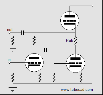
Here’s a test: Find the feedback loop in the above schematic. The answer is that the input tube’s plate resistor defines a feedback loop, as it brings the SRPP’s output back in inverted form to the bottom triode’s grid (input). In fact, the input tube can be seen as defining a voltage-to-current converter that turns the input signal’s voltage variation at its grid into current variation at its plate. The rest of the circuit can then be seen as constituting a current-to-voltage converter, as a variation in current flow across its feedback resistor (the input stage’s plate resistor), will produce a proportional variation in voltage at the output. 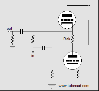
The advantage of such a feedback arrangement lies in the ability of this feedback loop to fly under the radar of 99.9% of tube fanciers and audio reviewers, which means that this circuit could be advertised as being feedback free (with only the readers of this journal knowing better). The disadvantage to this feedback arrangement lies in it not including the input tube within its purview. Additionally, the plate resistor’s value is effectively reduced in value by the feedback ratio of the SRPP portion of the circuit. This means more distortion from the input tube, as it would receive little distortion-lowering plate degeneration. 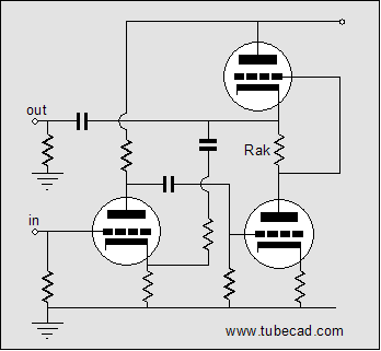
The above schematic shows an alternative approach. The input tube’s plate resistor now terminates into the B+ connection and the added feedback-loop resistor returns to its cathode. Nothing fancy is going on here, as the input triode and the bottom output tube define a generic cascaded two-tube grounded-cathode amplifier that includes a feedback loop, as shown below. 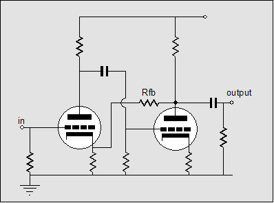 Here’s an variation on this theme: What if we make a unity gain buffer out the bottom augmented SRPP circuit? What would it look like? 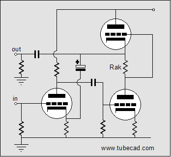
The circuit above looks almost he same as the first version, but there is a major difference. The feedback resistor has been reduced to zero ohms, eliminated, in other words. Now, all the amplifier’s output signal is brought back to the input tube’s cathode as 100% negative feedback. As an interesting aside, the input signal can easily swing far beyond the input tube’s cathode-to-grid voltage, as its cathode will follow is grid closely. Alternatively, we can attach the input tube’s cathode directly to the output, as shown below: 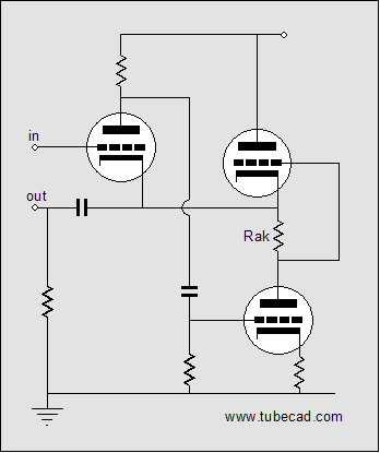
Which version is better? Better for what? is my usual reply. If the circuit is going to be a standalone buffer, then the first approach offers a ground-level input. If the buffer is going to be part of a larger circuit and it receives its input signal at some higher-than-ground voltage, the second approach will do away with the otherwise-needed coupling capacitor. For example: 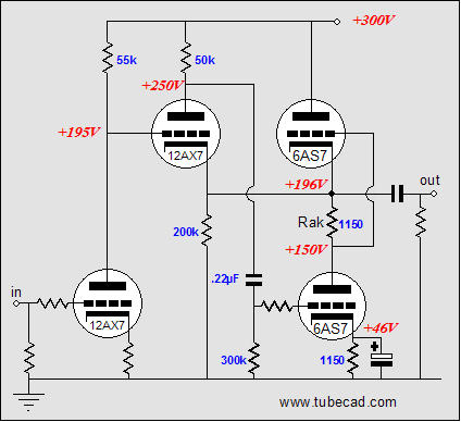
Putting it all together 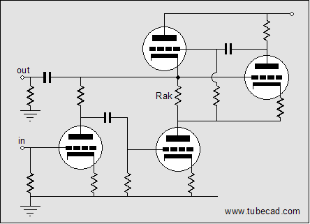
and 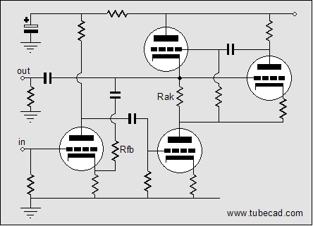
Both circuits can be further modified by filling the missing grid-stopper resistors and other supporting parts and example part values: 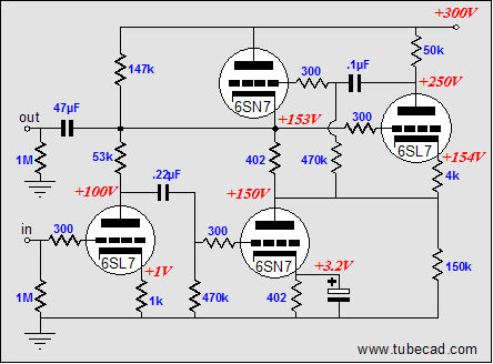 and 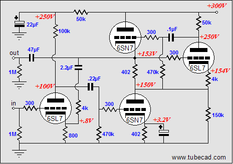
Conclusion As a piece of homework, try translating the last two circuits into solid-state versions, using only four transistors per circuit. //JRB |
Support the Tube CAD Journal & get an extremely powerful tube-amplifier simulator for TCJ Push-Pull Calculator

TCJ PPC Version 2 Improvements Rebuilt simulation engine *User definable
Download or CD ROM For more information, please
visit our Web site : |
|||


| www.tubecad.com Copyright © 1999-2005 GlassWare All Rights Reserved |