| John Broskie's Guide to Tube Circuit Analysis & Design |
04 August 2013
Where Did July Go?
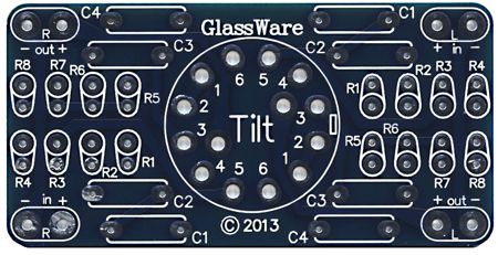
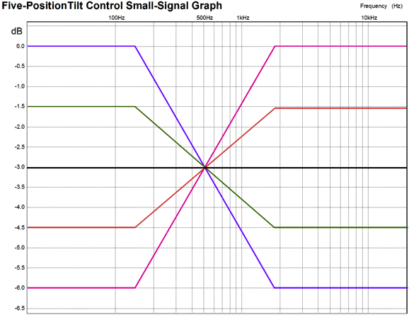
GlassWare Tilt Control
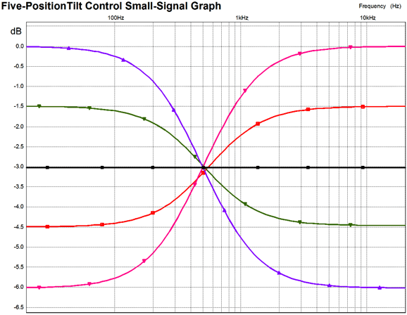
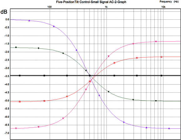
The actual five frequency plots are much smoother, as shown below.
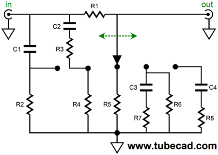
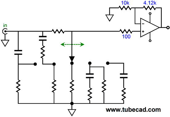
Achieving these five frequency response profiles requires five passive networks—all of which share resistor R1 as circuit element.
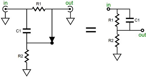
The first position is selected when the rotary switch is turned completely clockwise, which results in the junction of capacitor C1 and resistor R2 being selected.
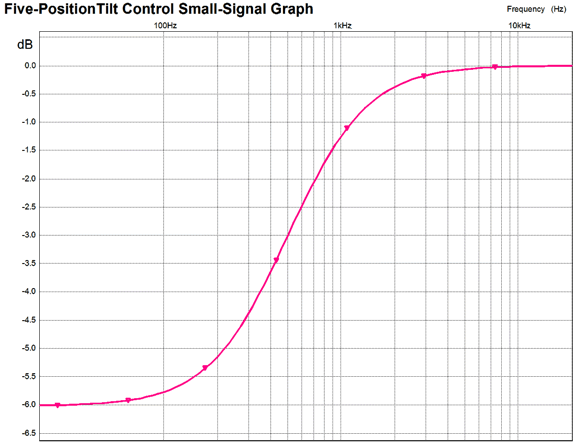
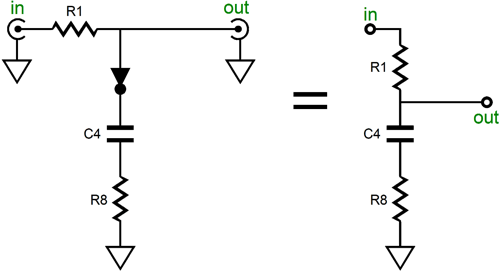
Since I have long ago discovered that many readers cannot see topology in an unfamiliar format, I have added the redrawn schematic on the right to make the shelving network's configuration clearer. A quick inspection reveals that DC voltage and low frequencies will be attenuated by the two-resistor voltage divider formed by R1 and R2. On the other hand, high frequencies will jump over resistor R1 and emerge un-attenuated. The difference in signal amplitude between high and low frequencies is equal to 20Log(1 + R1/R2) in dBs. If R1 and R2 are the same value, the difference is equal to -6dB. The lower frequency at which the signal strength begins to climb is equal to 1 / (2 • pi • R1 • C1). The high frequency at which the signal strength begins to flatten out is equal to 1 / (2 • pi • R1||R2 • C1). Since the GlassWare Tilt Control's center frequency is 500Hz and we need a 3dB cut and boost, the two transition frequencies must equal 500Hz/1.414 (353.6Hz) and 500Hz x 1.414 (707Hz), where 1.414 is the square root of 2. Both R1 and R2 equal 30k and C1 equals 15nF. If we run a SPICE simulation on this shelving network with these values, we get the following frequency plot.
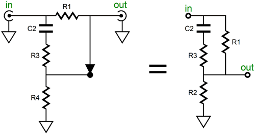
Rotating the switch one click back counterclockwise results in a smaller boost and cut, only 1.5dB. Once again, the center frequency is 500hz. The math gets much thicker with this more elaborate shelving network.
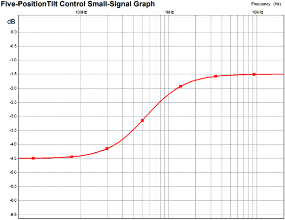
Nonetheless, the result is that the 1.5dB cut and boost are imposed on the frequency response and the center frequency is still 500Hz, which will be -3dB down, as in the previous shelving network. The SPICE plot is shown below.
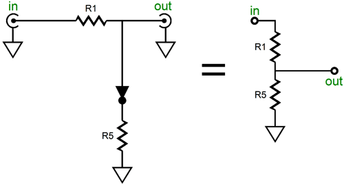
The center position is much easier to implement, as we only need a fixed -3dB attenuator, which can easily be made from two resistors.
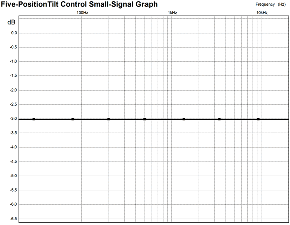
The input signal must be reduced to 70.7% of its original value. Since R1 equals 30k, R5 must equal about 70k. The closest 1% resistor value is 69.8k. The SPICE frequency plot is quite boring.
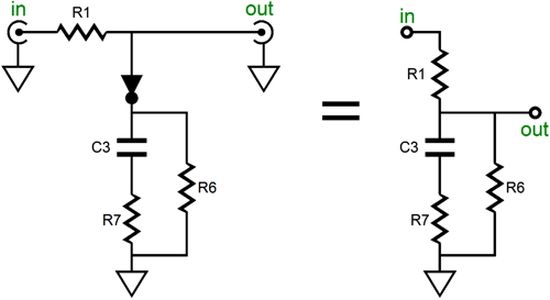
Moving one more click counter-clockwise gives us a +1.5dB bass boost and a -1.5dB cut in highs. Once again, the center frequency is 500Hz. You can readily see how at high frequencies, resistors R7 and R6 are in parallel with each other; but at DC and low frequencies, only resistors R1 and R6 are in series with each other.
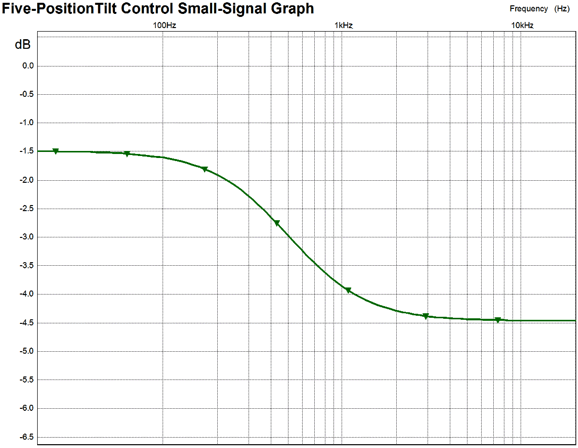
Using 4.3nF for C3 and 61.9k for R7 and 160k for R6 results in the following SPICE graph.
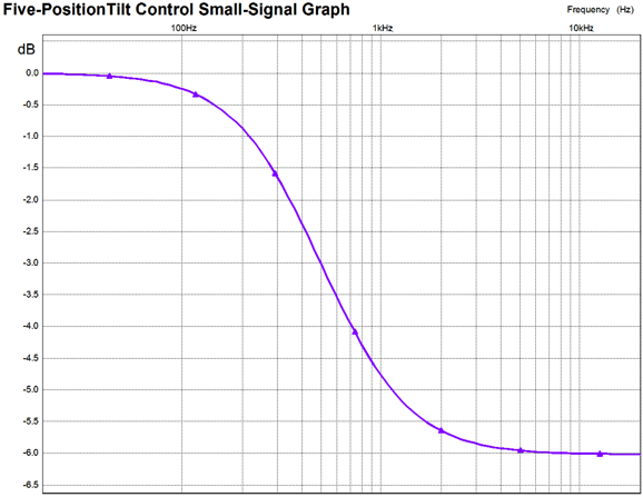
And our last position results in the biggest bass boost and the biggest cut in high frequencies (+3dB & -3dB). At the center frequency, 500Hz, the attenuation is -3dB. A quick inspection of the following network reveals that at DC and low frequencies, no attenuation occurs; but at high frequencies, resistors R1 and R8 define a two-resistor attenuator. If R8 equals 30k, the attenuation will be -6dB.
Using 7.5nF for C5 and 30k for R8 results in the following SPICE graph.
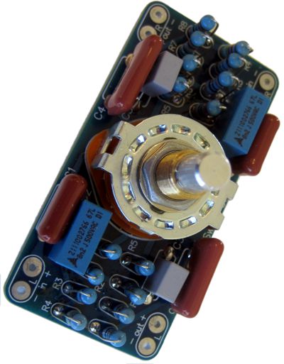
And there we have it: five positions, five different sonic presentations. I found the sonic results quite interesting. First of all, I was advised to make huge cuts and boosts to the signal, so even the near-deaf would notice the difference. Well, I am glad that I didn't, as the 1.5dB increments is plenty for most recordings. Yes, there are plenty of recordings that could use bigger sonic tilts, but the better solution would be to design and build a very-expensive 11-position tilt control. One result that impressed me greatly was listening to my Sennheiser HD650 and Grado SR-225 headphones with the GlassWare Tilt Control. They do not sound anything alike... without the Tilt Control that is. I found that the sonic difference could be substantially reduced by one click to the right with the HD650 headphones and one click to the left with the SR-225 headphones. Not exactly the same, but much closer than I ever thought possible. I also own AKG and Beyer headphones and I have been using all these headphones as tone controls of sorts, swapping one out for another as the music dictates the need for a different sonic presentation. This approach is neither elegant nor inexpensive. The much better approach is to seek out the most neutral headphones and then use a GlassWare Tilt Control to make the needed frequency adjustments. (The next missing sonic control required for great headphone listening is a stereo blend control that would undo some of the excessive stereo separation.) The PCB was made purposely small so it could fit within a 1U rack-mount enclosure. This required that the resistors be inserted perpendicular to the board, which is never to my liking, as I have big hands, but it wasn't that big of a deal. The bigger deal was something that I didn't expect. One problem we face today is that tight-tolerance polystyrene capacitors are no longer being made and finding tight-tolerance film capacitors of any type is difficult. (I can imagine the nightmare day when no small through-hole capacitors will be made, leaving us with only surface-mount capacitors.) I hadn't realized how bad things had gotten, until I tried sourcing the capacitors with a 0.4in lead spacing for the GlassWare Tilt Control. Very difficult indeed.
How To Use The GlassWare Tilt Control What about placing the Tilt Control after the 20k volume control? The highest output impedance from a potentiometer occurs at -6dB, where the Zo equals the potentiometer's resistance divided by four; in the case of a 20k potentiometer, 5k. The 5k of resistance results in shifting the center frequency up a tad, say 50Hz to 550Hz and making the bass boost bigger, along with increasing the insertion loss by 0.5dB, as the following graph shows.
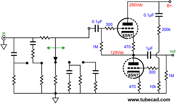
To be honest, although I know many audiophiles who would wet their pants at the sight of such asymmetry, the resulting plots are still quite useful. Remember: there is no perfect, no absolute tilt-control profile. Once we leave flat frequency response, we are on our own. Since the ear is less sensitive to low frequencies, the above set of frequency response plots may prove preferable to the those shown earlier. At the other end, the load impedance, the closer the load approaches infinity the better. So, placing the Tilt Control in front of a 20k potentiometer would be a truly bad idea, as would placing it in front of an amplifier with a 47k input impedance. In contrast, following the GlassWare Tilt Control with a cathode follower or an OpAmp is a good idea. The following schematic shows a Tilt Control cascading into an Aikido Cathode Follower.
Because the rotary switch is a shorting type, the output never loses contact with a path to ground, so the control itself can be used as the grid resistor. We could even use an OpAmp configured to deliver a gain of 1.4 (+3dB), which would undo the -3dB insertion loss.
The GlassWare Tilt Control kit is available now at the GlassWare-Yahoo store. It includes the PCB, rotary switch, and all the polypropylene capacitors (8) and 1% metal-film resistors (16).
Next Time
//JRB |
I know that some readers wish to avoid Patreon, so here is a PayPal button instead. Thanks.
John Broskie
And
High-quality, double-sided, extra thick, 2-oz traces, plated-through holes, dual sets of resistor pads and pads for two coupling capacitors. Stereo and mono, octal and 9-pin printed circuit boards available.
Designed by John Broskie & Made in USA Aikido PCBs for as little as $24 http://glass-ware.stores.yahoo.net/
The Tube CAD Journal's first companion program, TCJ Filter Design lets you design a filter or crossover (passive, OpAmp or tube) without having to check out thick textbooks from the library and without having to breakout the scientific calculator. This program's goal is to provide a quick and easy display not only of the frequency response, but also of the resistor and capacitor values for a passive and active filters and crossovers. TCJ Filter Design is easy to use, but not lightweight, holding over 60 different filter topologies and up to four filter alignments: While the program's main concern is active filters, solid-state and tube, it also does passive filters. In fact, it can be used to calculate passive crossovers for use with speakers by entering 8 ohms as the terminating resistance. Click on the image below to see the full screen capture.
Tube crossovers are a major part of this program; both buffered and un-buffered tube based filters along with mono-polar and bipolar power supply topologies are covered. Available on a CD-ROM and a downloadable version (4 Megabytes). |
|||


| www.tubecad.com Copyright © 1999-2013 GlassWare All Rights Reserved |