| John Broskie's Guide to Tube Circuit Analysis & Design |
| 19 November 2014
Batteries & Tubes
I figure that since I had in my last post dipped my little toe in the big lake, I might as well plunge in altogether and devote an entire post to the topic of batteries and tubes, where I would array as many varied uses for batteries in tube circuits as I could —well, as many as I could before I ran out of pixels or endurance. Since I just repeated the schematic from my last post, I may as well also repeat what I wrote about expense and hassle of batteries in audio equipment:
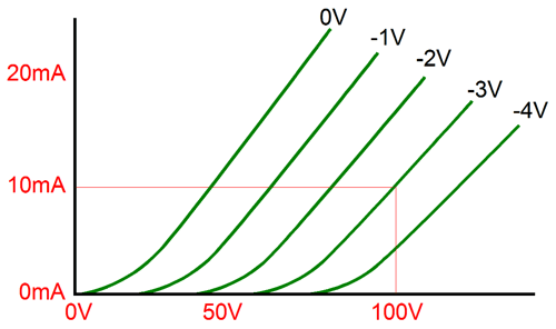
The punch-line, the bottom-line, the end-of-the-day conclusion is that if a battery is used not to deliver power but only provide a fixed voltage drop, so that the battery is not used up by the circuit but by the passing of time itself, then the battery is neither expensive nor in need of repeated replacement. Since the battery only serves as a self-powered voltage reference, the question about which battery type sounds best does not arise. (The answer, by the way, is the nickel–hydrogen type. Actually, a battery sonic shootout was held long ago in Silicon Valley. I didn't attended the event, but I did hear about the results: the winner was a vented NiCad battery used in airplane landing gear as an emergency back-up power source. No, you cannot buy one at Walmart.) The best place to start, as so often is the case, is with a triode's set of plate curves, as they reveal the essential voltage-current relationships for the triode.
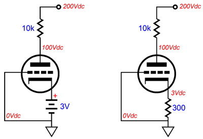
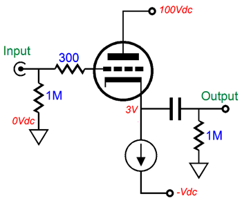
As you can see from the graph above, the triode can experience an idle current of 10mA over a wide range of negative grid and positive plate voltages; for example, with either a cathode-to-grid voltage of 0V, -1V, -2V, -3V, -4V—and any voltage in between; and that the cathode-to-plate voltage jumps up by a fixed amount each time (well very nearly fixed). The increase in plate voltage divided by the decrease in grid voltage reveals the amplification factor of the triode. For example, if the plate voltage goes up by 10V for each 1V decrement in grid voltage, then the triode's amplification factor (mu) is 10; if it went up by 40V, the amplification factor would be 40. Let's say that our target is an idle current of 10mA at a plate voltage of 100V. By inspecting the triode's plate curves we see that the grid must be 3V more negative than the cathode; or, put differently, the cathode must be 3V more positive than the grid. If we adopt the latter approach, we could use a 3V battery or a 300-ohm cathode resistor, as 10mA against 300 ohms equals a 3V voltage drop, to establish the desired +3Vdc cathode voltage.
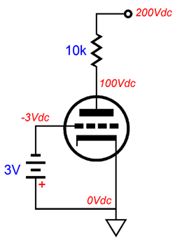
Alternatively, we could use either a negative power-supply rail or a battery to force the grid 3V negative relative to the cathode.
No doubt many observant readers have spotted that in the first two examples of cathode bias, the cathode-to-plate voltage is no longer 100V, but only 97V, as 3V was displaced by either the battery or cathode resistor. True enough, but with amplification factors above 10, we can usually get away with ignoring this discrepancy. On the other hand, with a low-mu triode, such as the 6AS7, whose mu is only 2, the cathode voltage will consume a huge portion of the available B+ voltage. (Other observant readers will note that in the example of the battery used in place of the cathode resistor, the battery is doing more than just provide a self-contained voltage reference. Do not worry; we will get to this type of setup.) So far these three examples are informative, but not very useful. For example, if we want to build a line-stage amplifier, then a few more parts will be needed, such as both an input and output coupling capacitors and two extra resistors.
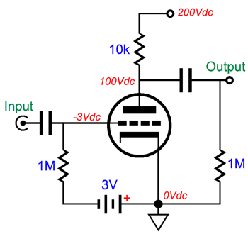
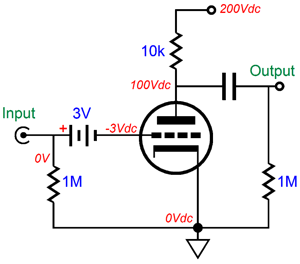
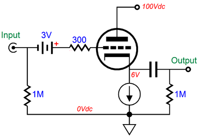
While we always expect a coupling capacitor at the output of a tube-based line-stage amplifier, we usually do not expect an input coupling capacitor. Well, we can lose the input coupling capacitor by rearranging the circuit elements.
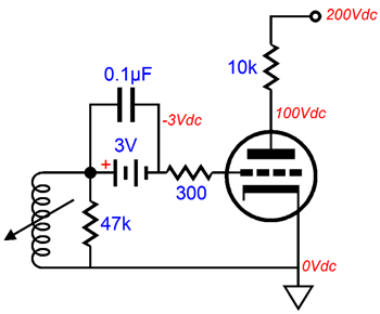
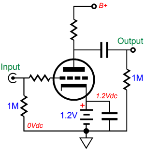
I admit that that this circuit looks a bit odd, mostly due to the battery seemingly doing nothing, as no current flows through it. Nonetheless, the battery is essential, as it establishes the required -3V bias voltage to the grid. (A grid-stopper resistor is also needed, but for the sake of clarity, I left it out of the schematic. Perhaps a mistake, as many find my schematics through a Google-Image search and do not read my explanations.) The 3V battery allows us to use fixed bias with the triode, without the need of having a negative power-supply rail (or a cathode-resistor and its bypass capacitor). The advantage to having the triode's cathode directly grounded is that we get higher gain, an improved PSRR figure, and lower output impedance from the triode. On the other hand, had we used an unbypassed cathode resistor, the triode would have yielded less gain, a bit worse PSRR figure, and higher output impedance—but it also would have delivered less distortion, as an unbypassed cathode resistor introduces some degenerative negative feedback, which linearizes the triode's transfer curve. Tradeoffs, in other words. We must decide which attribute needs the most emphasis. Sometimes it will be lower gain and lower distortion; other times, improved PSRR and more gain. One example of the latter choice is in a phono stage, wherein the signal swings are very small, so distortion is already very low, but where improved PSRR and higher gain are essential.
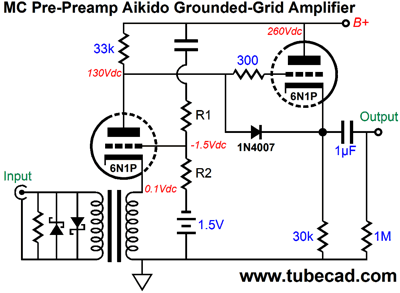
Shown above is the input stage of a phono preamp. The triode's gain in this circuit is equal to Gain = muRa/(rp + Ra) And its output impedance equals: Zo = Rp || Ra The PSRR is given by: 20Log[Ra/(Ra + rp)] What is missing is a few more bells and whistles, such a bypass capacitor for the battery and a grid-stopper resistor.
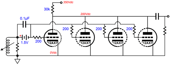
Now let's get extra fancy. The 12AX7 offers the highest amplification factor of the readily available twin triodes, which would seem to recommend its use for phono preamps. Indeed, for most high-output moving-coil and moving-magnet phono cartridges, this recommendation is a sound one. But where low-output cartridges are concerned, the 12AX7 higher noise contribution compromises its higher gain contribution. (Triodes with higher transconductance figures yield lower noise, as they are effectively lower resistance devices.) One workaround is to use a step-up transformer. Another workaround is to use many triodes in parallel, as this will reduce the noise contribution by effectively increasing the transcendence. In the following circuit, we see four 12AX7 triodes placed in parallel, with each cathode being directly grounded. Each triode draws 1.25mA of idle current, which explains how we can use a 30k plate resistor, where a 150k to 250k plate resistor would be more typical in a 12AX7-based phono stage.
The combined idle current draw of 5mA against the 30k resistor results in a voltage drop of 150V. The combined output impedance is 10k, which would make driving a passive RIAA EQ network easier to do; and the PSRR is -9.5dB, which in itself isn't that stellar, but it is still an improvement over what four unbypassed cathode resistors would have yielded. The gain comes in at 36.5dB, which means that two such cascading gain stages, with a passive RIAA EQ network in between, would yield a final gain of about 52dB, as the passive RIAA EQ network entails an insertion loss of at least 20dB. Yes, eight 12AX7s would be needed for stereo playback, but that small phalanx of tubes would certainly look impressive.
Batteries and Cathode Followers
So, how do we eliminate the need for a negative power-supply rail? We add a battery, placing it in series with the triode's grid. Now, the cathode voltage is sufficiently high to use a solid-state constant-current source and allow bigger output voltage swings.
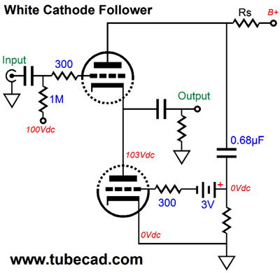
Of course, not all triodes would need the extra grid voltage, for example, the 6BX7 or 12B4 naturally run high cathode voltages, due to their low amplification factors; but even these low-mu triodes could benefit from the extra grid bias voltage, if the plate voltage was quite a bit lower, say only 48Vdc. Here is another battery variation, a White cathode follower, one that forgoes all cathode resistors and bypass capacitors.
Here the battery biases the bottom triode, with the bottom triode's cathode directly connected to ground. From this circuit to the Broskie cathode follower is an easy move.
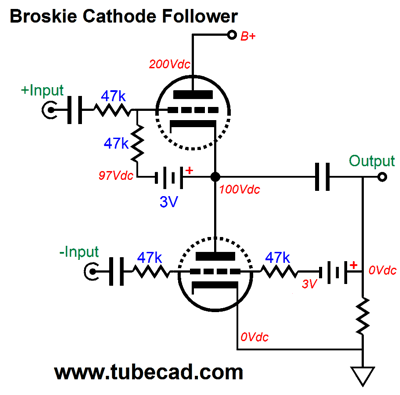
Two balanced input signals enter and a single unbalanced output exits. Two batteries are required, but no cathode resistors are used; thus, the output impedance is low as it can get in this circuit, roughly the inverse of the transconductance of the triode used. For example, with a 6DJ*, the output impedance would be about 100 ohms.
Batteries and Cathode-Coupled Amplifiers
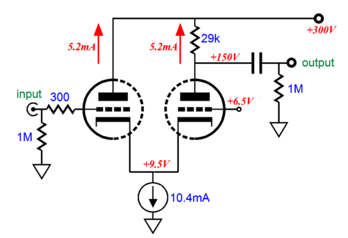
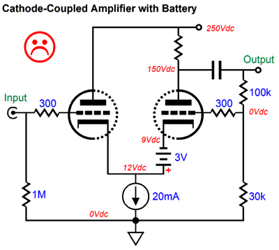
One possible workaround is to incorporate a battery to make the output triode's cathode less negative relative to the input triode's cathode.
The problem with this circuit is that the battery sees all the current flow that the left triode experiences, which is the opposite of the battery just supplying a fixed DC offset voltage, but no power. Indeed, the battery could overheat from the current flow into to it, thereby damaging it. The solution is to move the battery to the grid position instead, where it experiences no current flow.
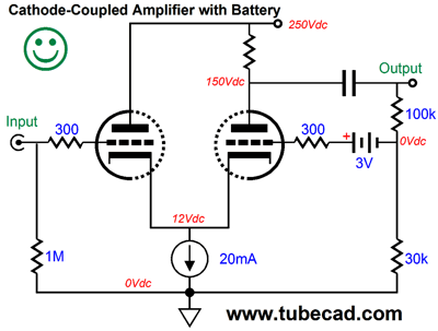
Now, the battery only provides a fixed voltage drop, but no current; and the two triodes undergo the same idle current flow, in spite of the dissimilar cathode-to-plate voltages.
An Exception to the Rule Nonetheless, in the typical tube circuit, say a line-stage amplifier based on a 6SN7, the idle current flow through the triode can be viewed as a form of trickle charging for the battery. Trickle charging (also known as maintenance charging) is when a weak current is allowed to flow into the battery at just a high enough rate to keep the battery fully charged, but not so high as to cause overcharging. This is not an exact science. I have read various optimum trickle charge ratios, from a hot 10% of maximum battery capacity to a low 2%. For example, if a NiCad battery is rated for 1000 mA-hours. Then 20mA to 100mA of current is applied. By the way, many leave their rechargeable batteries in an active, fast-charge charger station, charging away until they are needed and removed. A bad idea, as it will shorten the battery's useful life span. A light enough trickle charge, in contrast, while not perfect, will not shorten the battery's life by nearly as much, if at all.
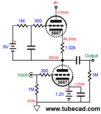
Some experimentation is definitely required. Fortunately, the setup is simple, as is the testing. For example, in the above schematic, we see a triode using a rechargeable battery to provide the needed cathode bias. The bypass capacitor that shunts the battery is just a nod to audio nervousness and may not be necessary. A 6SN7 with a cathode-to-plate voltage of 80V and the 1.2V cathode voltage will draw 5mA. Well, it would be interesting to use a fully charged battery and then measure its voltage over time, both with the line-stage amplifier on and off. If more plate voltage is desired, then two batteries can be placed in series, which would yield 2.4V of cathode bias voltage; with a plate voltage of 150V and the 2.4V cathode voltage, the 6SN7 draws 10mA of idle current. Don't like the 6SN7, well how about a 5687?
The 1.2V battery is a rechargeable type, whereas the 9V battery is just a quality alkaline type, what we used to call a transistor battery. Note the low B+ voltage of only 110Vdc. Also note the 1.02k cathode resistor between triodes. This resistor and the top triode's plate resistance (and mu) combine to produce an active plate load equal to a 20.5k resistor. If we replaced the active load with a 20.5k plate resistor, we would have to up the B+ voltage to 250Vdc, as the resistor would displace 205 volts. In other words, although this active load is not a constant-current source, it does offer more impedance than the equivalent plate resistor would; in this example, a 6k resistor. Is that important? Yes, as it allows greater gain and improved PSRR.
Other Uses for Batteries
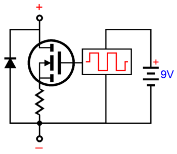
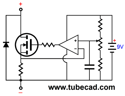
Well, John's inspiration stirred me to build an independent, floating high-voltage, constant-current source.
Housed in a plastic enclosure, my floating constant-current source held a high-voltage MOSFET, a few resistors and capacitors, a potentiometer, and an OpAmp. On the outside of the box two five-way binding posts and current-setting knob and on-off switch were presented. The 9V battery ran the OpAmp and the OpAmp controlled the current flow through the MOSFET. So, what good was this piece of electronic test equipment? I found it to be a real time saver, as I would use it in place of a plate resistor, so I could quickly determine optimal operating points. In addition, I used it to match power output tubes, by attaching the floating constant-current source to the cathode and ground, which allowed me to measure the cathode voltage on each output tube tested. Couldn't I have used a transformer-based power supply, one that just plugged into the wall? Yes, I could have, but then issues of safety and added noise would arise. There is a lot to be said for a floating, independent piece of electronic gear.
Next Time
For those of you who still have old computers running Windows XP (32-bit) or any other Windows 32-bit OS, I have setup the download availability of my old old standards: Tube CAD, SE Amp CAD, and Audio Gadgets. The downloads are at the GlassWare-Yahoo store and the price is only $9.95 for each program. http://glass-ware.stores.yahoo.net/adsoffromgla.html So many have asked that I had to do it. WARNING: THESE THREE PROGRAMS WILL NOT RUN UNDER VISTA 64-Bit or WINDOWS 7 & 8 or any other 64-bit OS. I do plan on remaking all of these programs into 64-bit versions, but it will be a huge ordeal, as programming requires vast chunks of noise-free time, something very rare with children running about. Ideally, I would love to come out with versions that run on iPads and Android-OS tablets.
//JRB |
I know that some readers wish to avoid Patreon, so here is a PayPal button instead. Thanks. John Broskie
Kit User Guide PDFs
E-mail from GlassWare Customers
High-quality, double-sided, extra thick, 2-oz traces, plated-through holes, dual sets of resistor pads and pads for two coupling capacitors. Stereo and mono, octal and 9-pin printed circuit boards available.  Aikido PCBs for as little as $24 http://glass-ware.stores.yahoo.net/
Support the Tube CAD Journal & get an extremely powerful push-pull tube-amplifier simulator for TCJ Push-Pull Calculator
TCJ PPC Version 2 Improvements Rebuilt simulation engine *User definable
Download or CD ROM For more information, please visit our Web site : To purchase, please visit our Yahoo Store: |
|||


| www.tubecad.com Copyright © 1999-2014 GlassWare All Rights Reserved |